check AUDI S8 2013 Owner's Manual
[x] Cancel search | Manufacturer: AUDI, Model Year: 2013, Model line: S8, Model: AUDI S8 2013Pages: 318, PDF Size: 79.34 MB
Page 69 of 318
Full-length center
console
Overview
Applies to vehicles: with full-le ngth center console
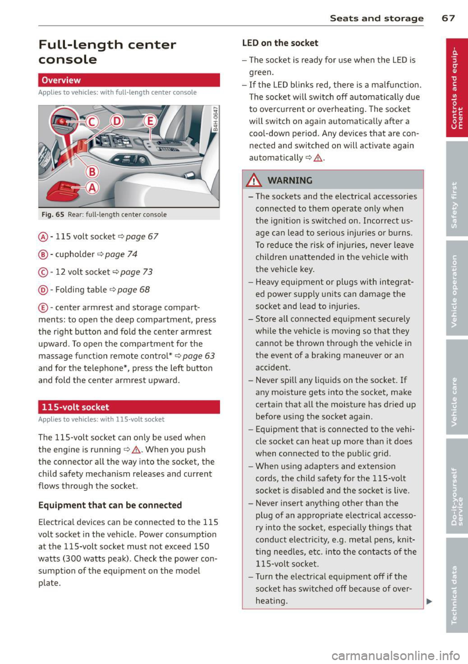
Fig. 65 Rear: full -lengt h center console
@ · 115 volt socket c::> page 67
@ · cupholder c::> page 74
© -12 volt socket c::> page 73
@· Folding table c::> page 68
© ·center armrest and storage compart
ments : to open the deep compartment, press
the r ight button and fold the center armrest
upward. To open the compartment for the
massage function remote control*
c::> page 63
and for the telephone*, press the left button
and fold the center armrest upward.
115-volt socket
Applies to vehicles: with 115-volt socket
The 115-vo lt socket can on ly be used when
the engine is running
c::> .&. . When you push
the connector all the way into the socket, the
child safety mechanism releases and current
flows through the socket.
Equipment that can be connected
Electrical devices can be connected to the 115
volt socket in the vehicle. Power consumption
at the 115-volt socket must not exceed 150
watts (300 watts peak) . Check the power con
sumpt ion of the equipment on the model
plate .
Seats and storage 67
LED on the socket
-The socket is ready for use when the LED is
green.
- If the LED blinks red, there is a malfunction.
The socket wi ll switch off automatically due
to overcurrent o r overheating . The socket
will switch on again automatica lly after a
cool-down period . Any devices that are con
nected and switched on will activate again
automatically
c::> .&. .
A WARNING
-- The sockets and the-electrical accessories
connected to them operate only when
the ignition is switched on. Incorrect us
age can lead to ser ious injuries or burns.
To reduce the risk of injuries, never leave
children unattended in the veh icle with
the vehicle key.
- Heavy equipment or plugs with integrat
ed power supply units can damage the
socket and lead to injuries.
- Store all connected equipment securely
while the vehicle is moving so that they
cannot be thrown through the vehicle in
the event of a braking maneuver or an
accident.
- Never spill any liquids on the socket . If
any moisture gets into the socket, make
certain that all the moisture has dried up before using the socket again .
- Equipment that is connected to the vehi·
cle socket can heat up more than it does
when connected to the public gr id.
- When using adapters and extension
cords, the child safety for the 115-volt
socket is disabled and the socket is live .
- Never insert anything other than the
plug of an appropriate electrical accesso
ry into the socket, especially things that
conduct e lectricity, e.g. meta l pens, knit
ting need les, etc. into the contacts of the
115-volt socket.
- Turn the electrical equ ipment off if the
socket has switched off because of over
heating.
Page 70 of 318
68 Seats and storage
(D Note
-Always follow the manufacturer's in
str uctions for all electrical accessories
you want to use with the electrical sock
et!
- Do not connect lamps that contain a ne
on tube. For technical reasons the lamp
may be damaged.
- Do not connect any 230-volt equipment
to the 115-volt socket. The equipment
may be damaged. If necessary, check the
permissible voltage for the equipment
on the model label.
- In the case of some power packs, e.g . for
a laptop computer, the built-in overcur
rent shutoff prevents it from being
switched on because of excessive start
up current. In this case, disconnect the
power pack from the consumer and re
connect it after about 10 seconds.
@ Tips
- Unshielded equipment may cause inter
ference in the radio and the vehicle elec
tronics.
- Some equipment may work properly be
cause of the reduced power (wattage),
available from the socket.
Folding table in the center console
Applies to vehicles: with folding table in the center con·
sole
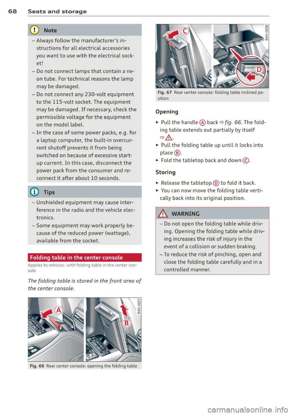
The folding table is stored in the front area of
the center console .
Fig. 66 Rear cente r conso le: opening the fo lding table
Fig. 67 Rear center console: folding table inclined po ·
si tion
Opening
.. Pull the handle @back ¢ fig. 66. The fold
ing table extends out partially by itself
¢,&. .
.. Pull the folding table up until it lock s into
place @.
.. Fold the tabletop back and down @.
Storing
.. Release the tabl etop @ to fold it back.
.. You can now move the folding table verti
cally back into its original position.
A WARNING
--=
- Do not open the folding tab le while driv-
ing. Opening the folding table while driv
ing increases the risk of injury in the
event of a collision or sudden braking .
- To reduce the risk of pinching, open and
close the folding table carefully and in a
controlled manner.
Page 74 of 318
72 Seats and storage
-When not in use, to reduce fuel consump
tion, wind noise and to guard against theft.
A WARNING
- Use of an unapproved roof rack or incor
rect mounting of an approved roof rack
can cause the roof rack or the items at
tached to it to fall off the roof onto the
road .
- Objects falling from the roof of a vehicle
can cause a crash and personal injury .
- Only mount the roof rack on the desig
nated locations on the roof
c::> fig. 7 4.
-The roof rack system must be installed
exactly according to the instructions pro
vided.
- When driving with a roof rack system,
changes to the center of gravity and wind
resistance can change the vehicle han
dling and lead to a collision . Always
adapt your driving and your speed to the
current conditions.
- Your vehicle warranty does not cover any
damages to the vehicle caused by using
roof racks or mounting structures not
approved by Audi for your vehicle. The
same applies to damage resulting from
incorrect roof rack installation.
- Always check the roof rack mountings
and hardware before each trip and dur
ing a trip to make sure everything is se
curely tightened. If necessary, retighten
the mountings and check the entire sys
tem from time to time.
- After mounting a roof rack system, or
when you transport objects on the roof
of your vehicle, the height of the vehicle
is naturally increased. Be careful when
driving under low bridges or in parking
garages for example . This could cause
damage to the load and even the vehicle itself.
- Make sure the open rear lid and the sun
roof* do not come into contact with the
roof rack.
Loading the roof rack
Always distribute loads evenly. Make sure
anything on the roof rack is securely tied
down.
.. Always distribute the loads on the roof rack
evenly .
.. Always attach items to the roof rack secure-
ly before you drive off.
The maximum permissible roof weight is
220
lb (100 kg).
The roof weight is the total of
the weight of the roof rack, the attachments
and the cargo you are carrying. You must also
not exceed the maximum load weight for the
roof rack you are using.
When using a roof rack system which has a lower load carrying capacity, you must not use
up the total maximum permissible load carry
ing capacity specified above. Instead, you
should load the roof rack system only to the
maximum capacity specified by the manufac
turer of the roof rack system .
A WARNING ,_
Weak, damaged or improper straps used
to secure items to the roof rack can fail
during hard braking or in a collision and
cause serious personal injury .
- Make sure the roof rack is installed exact
ly as specified above
c::> page 71.
-Always use suitable mounting straps for
securing items to the roof rack to help
prevent items from shifting or flying for
ward .
- Items on the roof rack must always be securely mounted .
- The use of a roof rack can negatively af
fect the way a vehicle handles . Cargo
that is large, heavy, bulky, long or flat
will have a greater negative influence on
the vehicle's aerodynamics, center of
gravity and overall handling. Always
drive slowly, avoid sudden braking and
maneuvers when transporting cargo on
the roof of your vehicle.
Page 78 of 318
76 Seats and storage
-the temperature in the luggage compart
ment is below 131 °f (55 °C). The cooler
switches off automatically if the tempera
ture in the luggage compartment exceeds 131 °f (55 °C). Once the tempera ture falls
below 131 °f (55 °C) again, the cooler
switches on aga in automatically .
- the battery is adequately charged . The cool
er switches off automatically if the vehicle
battery voltage falls below a minimum lev
el. This prevents the battery from discharg
ing. The cooler switches back on again auto
matically when the battery voltage increases
again (e.g . after starting the engine).
The cooler cools to 42.8 °f
(+ 6 °C) and the
freezer cools to 21.2 °f (-6 °C) in opt imum
cooling conditions . The cooling performance
is affected by the temperature in the luggage
compartment. The temperature inside the
cooler will be higher if the luggage compart
ment is hot.
A WARNING
To avoid putting the occupants at any risk, please observe the following safety rules:
- The maximum capacity is 2.5 kg (5.5
lbs.).
- Never overload the cooler. This could
cause injury in the event of a collision or
sudden braking.
- The cooler lid must always be kept closed
while you are driving. Make sure the re
taining catch is securely engaged. The contents of the coo ler could be thrown
forward into the passenger compart
ment in the event of a collision or under
sudden braking -risk of injury!
- Inflammable liquids, gas canisters, etc.
must not be stored in the cooler -risk of
explosion! This also includes any prod
ucts that might emit volatile or inflam
mable gases.
- Liquids will freeze at temperatures at or
below 32 °f (0 °C) and may cause glass
bottles to burst!
(D Note
- The ventilation openings for the cooler
are located on the back panel trim in the
luggage compartment and
must be kept
clear at all times.
- If the cooler is not functioning properly,
switch it off to prevent further damage.
Have it checked by a qualified workshop.
Operation
App lies to vehicles: wit h cooler
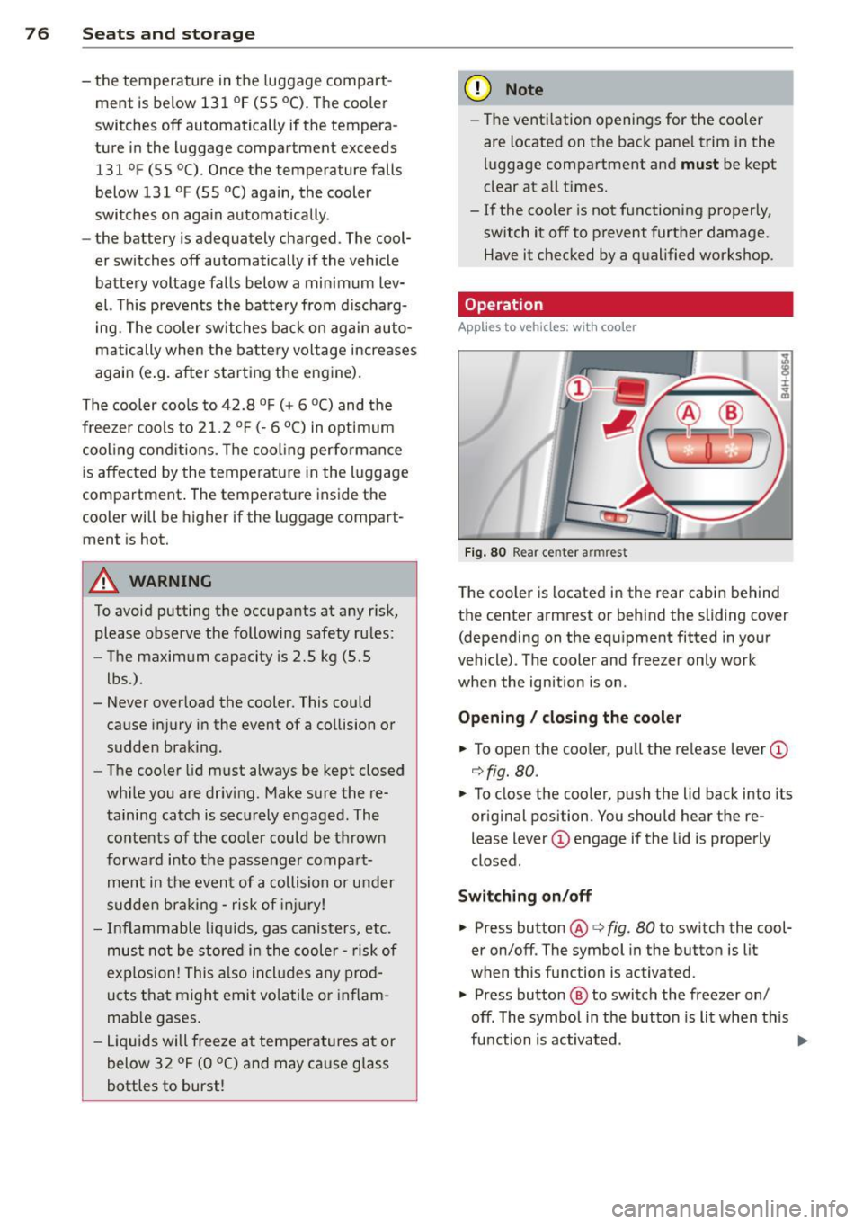
Fig. 80 Rear cen ter armrest
The cooler is located in the rear cabin behind
the center armrest or behind the sliding
cover
(depending on the equipment fitted in your
vehicle) . The cooler and freezer only work
when the ignition is on .
Opening / closing the cooler
.,. To open the cooler, pull the release lever(!)
c!> fig. 80.
.. To close the cooler, push the lid back into its
original position . You should hear the re
lease lever
(D engage if the lid is properly
closed.
Switching on/off .,. Press button @c::>fig.
80 to switch the cool
er on/off. The symbol in the button is lit
when this function is a ctivated .
.. Press button
@ to switch the freezer on/
off . The symbol in the button is lit when this
function is activated.
Page 84 of 318
82 On the road
On the road
Steering
Adjusting steering wheel position
The steering wheel position can be adjusted
for height and reach .
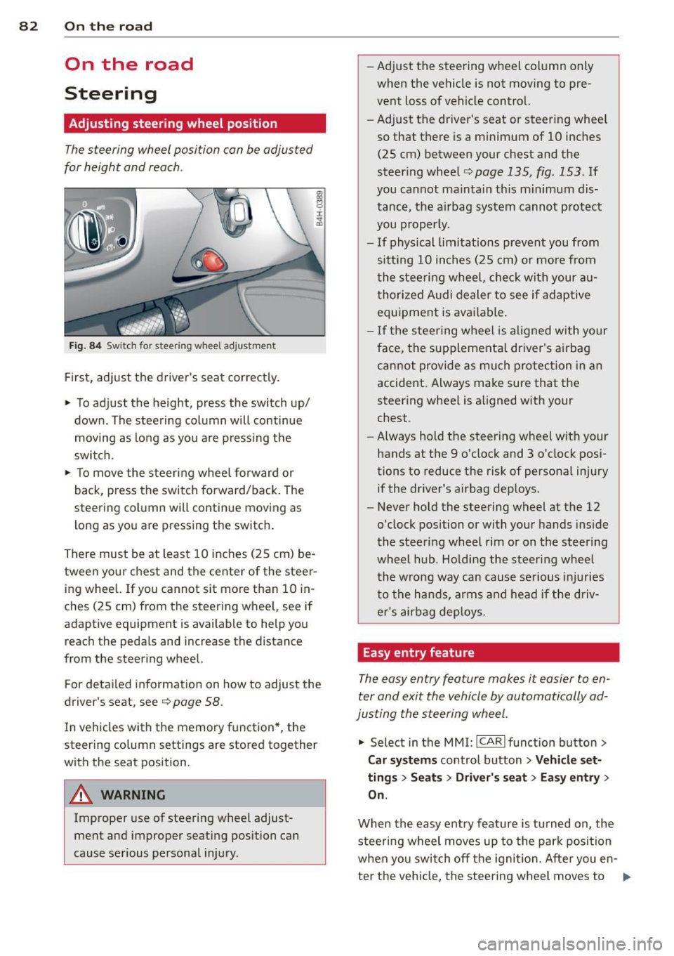
Fig. 84 Switch for steering whee l adjustment
F irst, adjust the driver's seat correctly.
• To adjust the height, press the switch up/
down. The steering column will continue
moving as long as you a re pressing the
switch.
• To move the steeri ng wheel forward or
back, press the switch forward/back . The
steering column wi ll continue moving as
long as you are pressing the switch .
There must be at least 10 inches (25 cm) be
tween your chest and the center of the steer ing wheel. If you cannot sit more than 10 in
ches (25 cm) from the steering wheel, see if
adaptive equipment is available to help you
reach the pedals and increase the distance
from the steering wheel.
For detai led informat ion on how to adjust the
driver's seat, see
Q page 58.
In vehicles with the memory function* , the
steering column settings are stored together
with the seat position.
A WARNING
Improper use of steering wheel adjust
ment and improper seating position can
cause serious personal injury . -
Adjust the steering wheel col umn only
when the vehicle is not mov ing to pre
vent loss of vehicle control.
- Adj ust the driver's seat or steering whee l
so that there is a m inimum of 10 inches
(25 cm) between your chest and the
steer ing wheel
Q page 135, fig . 153 . If
you cannot maintain th is m inimum dis
tance, the airbag system cannot p rotect
you properly.
- If physical limitations prevent you from sitt ing 10 inches (25 cm) or more from
the steering wheel, check wit h your au
thorized A udi dealer to see if adaptive
equipment is available .
- I f the steering wheel is al igned with your
face, the supplementa l driver's airbag
cannot provide as much protection in an
accident. Always make sure that the
steering whee l is aligned with your
chest.
- Always hold the steering wheel w ith your
hands at the 9 o'clock and 3 o'clock posi
tions to reduce the risk of persona l injury
if the dr iver's airbag dep loys.
- Never hold the steering wheel at the 12
o'clock position or with your hands inside
the steeri ng wheel rim or on t he steering
wheel hub. Holding the steer ing wheel
the wrong way can cause serious injuries
to the hands, arms and head if the driv
er's airbag deploys.
Easy entry feature
The easy entry feature makes it easier to en
ter and exit the vehicle by automatically ad
justing the steering wheel.
• Select in the MMI : ICAR lfunction button>
Car sy st e m s control button > Ve hicle set·
tin gs > Se ats > Driver's s eat > Ea sy entr y>
On .
When the easy entry feature is turned on, the
steering wheel moves up to the park position
whe n you switch off the ignition. Afte r you en-
ter the ve hicl e, the steering wheel moves to .,..
Page 91 of 318

@ Tips
When you stop and the start-stop-system
turns the engine off, the ignition remains on. Make sure that the ign ition is switched
off before exiting the vehicle.
General information
App lies to vehicles: with Start-Stop-System
The standard Start-Stop-mode can be cancel·
led for different system-related reasons.
Fig. 89 Instrument cluster : eng ine-Stop temporar ily
u navailable
Engine will not switch off
Before each stop phase, the system checks if
certain cond itions have been met . For exam
p le, the engine will
not be switched off in the
following situations:
- The engine has not reached the minimum
required temperature for Start -Stop-mode .
- The interio r temperature selected by the A/C
system has not been reached.
- Th e outside temperature is extremely h igh/
low.
- The windshield is being defrosted
9page 81.
- The parking system* is switched on.
- The battery charge level is too low .
- The steering wheel is sharply turned or there is a steer ing movement.
- After engaging the reverse gear.
- On sharp inclines .
The
(jj indicator light appears in the informa
tion line in the instrument cluster display
9fig. 89.
On the road 89
Engine automatically restarts
The stop phase is interrupted in the following
situations, for example. The engine restarts
without any action by the driver.
- The interior temperature varies from the
temperature selected in the A/C system.
- The windsh ield is being defrosted
9page 81.
-The brake pedal is pressed severa l times in a
row.
- The battery charge level becomes too low .
- High power consumpt ion.
@ Tips
If you shift into the D, Nor S positions af
ter sh ifting into
reverse, the vehicle must
be driven faster than 6 mph (10 km/h) in
order for the engine to sw itch off aga in.
Switching the Start-Stop-System on/off
manually
App lies to vehicles: wi th Start-Stop-Sys te m
If you do not wish to use the system, you can
switch it off manually.
Fig. 90 Center console: Start-Stop-System button
.,. To switch the Start-Stop-System off/on
manually, press the
l "'I button. The LED in
the button turns on when the system is
sw itched off.
@ Tips
If you switch the system off during a stop
phase, the engine will start again auto
matically.
Page 96 of 318
94 Audi adapti ve cruise control and bra king gu ard
vehicles or obstacles that are not moving
can trigger a collision warning and if con
firmed by the v ideo camera, an acute col
lis ion warn ing .
- For safety reasons, do not use adaptive
cruise co ntrol when driving on roads with
many curves, when the road surface is in
poor condit ion and/or in bad weather
(such as ice, fog, gravel, heavy rain and
hydroplan ing) . Using the system under
these cond it ions cou ld result in a co lli
sion .
- Swi tch adap tive c ruise control off tempo
rar ily when driv ing in turning lanes, on
expressway exits or in construction
zones . This prevents the vehicle from ac
celerat ing to the set speed when in these
situations.
- The adapt ive cruise control system wi ll
not brake by itse lf if you put your foot on
the accelerator pedal. Doing so can over
ride the speed and d istance regulation .
- When approaching stationary objects such as stopped traff ic, adaptive cruise
co ntrol will not respond and braking
guard w ill have limited function.
- The adapt ive cruise control system and
braking guard do not react to people, an
imals, objects c rossing the road or on
coming objects .
- The function of the radar senso rs can be
affected by reflective objects such as
guard rai ls , the entrance to a tunnel,
heavy rain or ice.
- Never follow a ve hicle so closely that you
cannot stop your vehicle safe ly. The
adaptive cruise contro l canno t slow or
brake the vehicle safely when you follow
another vehicle too closely. Always re
member that the automatic braking
function cannot br ing the vehicle to a
sudden or emergency stop under these condit ions.
- To prevent unintended operation, always switch ACC off when it is not being used. (D Note
The sensors can be displaced by impacts or
damage to the bumper, wheel housing and
underbody. That cou ld affect the adaptive
cruise control system and brak ing guard.
Have your authorized Aud i dea ler or au
thorized Audi Service Facility check their
funct ion .
In curves
Applies to vehicles: with Audi adaptive cru ise contro l
I
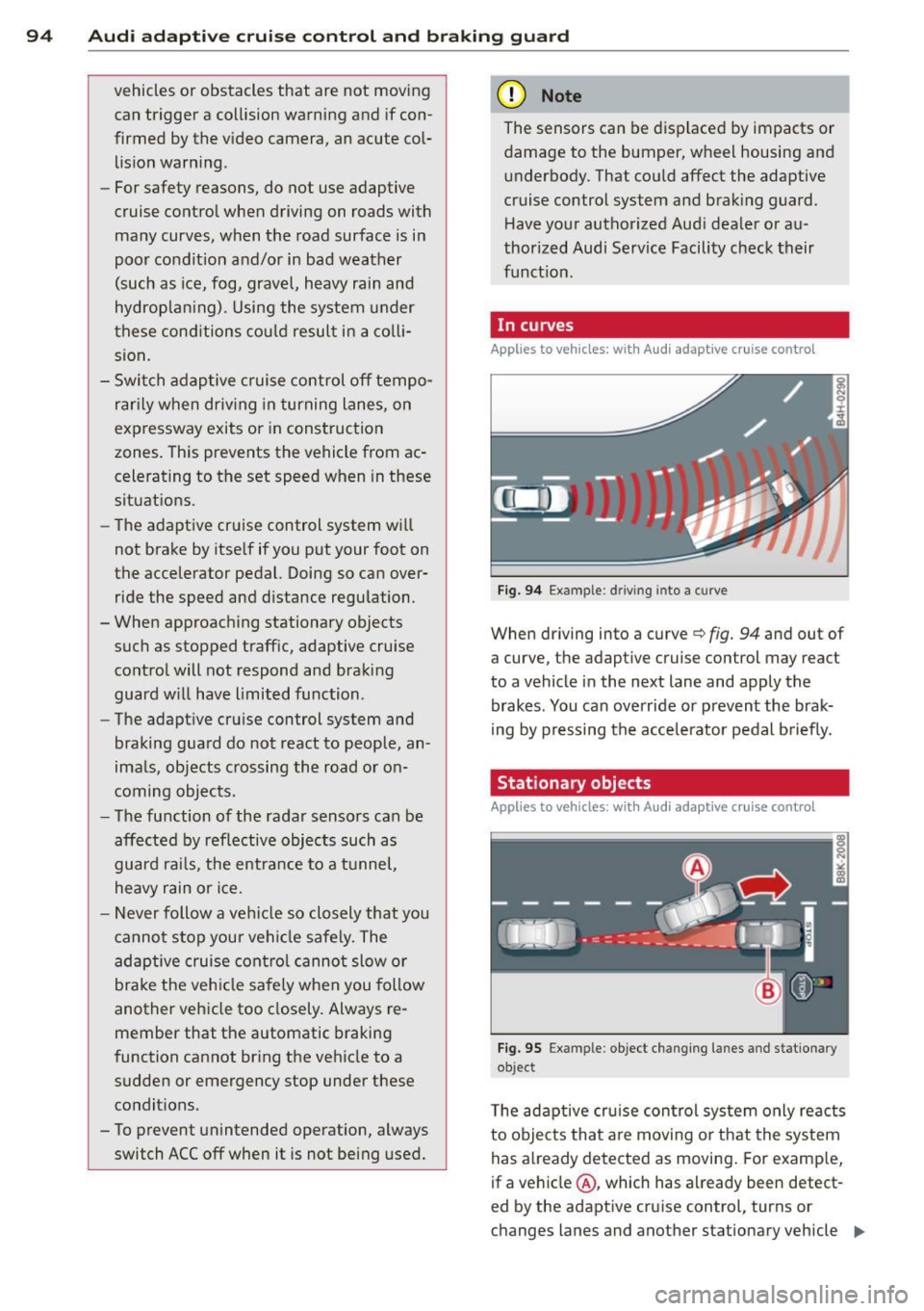
Fig. 9 4 Exampl e: dri ving in to a curve
When d riving into a curve c> fig. 94 and out of
a curve, the ad aptive cruise control may react
to a vehicle in the next lane and apply the
brakes. You can override or prevent the brak
i ng by pressing the acce lerator pedal b riefly .
' Stationary objects
Applies to vehicles: with Audi adaptive cruise control
Fig. 95 Exampl e: objec t ch anging l anes and sta tio nar y
object
T he adaptive cru ise control system only reacts
to objects that a re mov ing o r that the system
has already detected as moving . For examp le,
if a vehicle @, which has already been detect-
ed by the adaptive c ruise contro l, tu rns or
ch anges lanes and another stationary vehicle .,.
Page 106 of 318
104 Audi lane assist
Setting the warning point and steering
wheel vibration
Applies to vehicles: with lane assist
You can adjust individual settings in the MMI.
.. Se lect: ICARI function button> Car systems
control button > Driver assist > Audi lane
assist .
Setting the warning point
Early: With this setting, a warning is provided
before a wheel touches the detected lane
boundary line . The warning depends on the
angle in which the veh icle is approaching the
line. The distance at which the warning is giv
en increases as the angle becomes sharper. If
you dr ive towa rd a boundary line at a very
sha rp angle, the warning will come just before
a wheel touches the line.
Medium : With this setti ng, the warn ing po int
is adapted to the course of the road, the lane
width and the speed. You wi ll sti ll be warned
if you cross slightly over a dotted line when
driving on curves.
Late : This setting has the same properties as
medium. You will only be warned once a
wheel crosses a detected line.
Setting the steering wheel vibration
The steering wheel v ibration can be set to
Low , Medium or Strong . Selecting each of the
settings will cause the steering wheel to vi
b rate so you can check the strength of the vi
bration in that setting.
(D Tips
Your settings are automatically stored and
assigned to the remote contro l key being
used .
Page 107 of 318
Audi side assist Lane Change Assistant
Description
App lies to vehicles: with si de assist
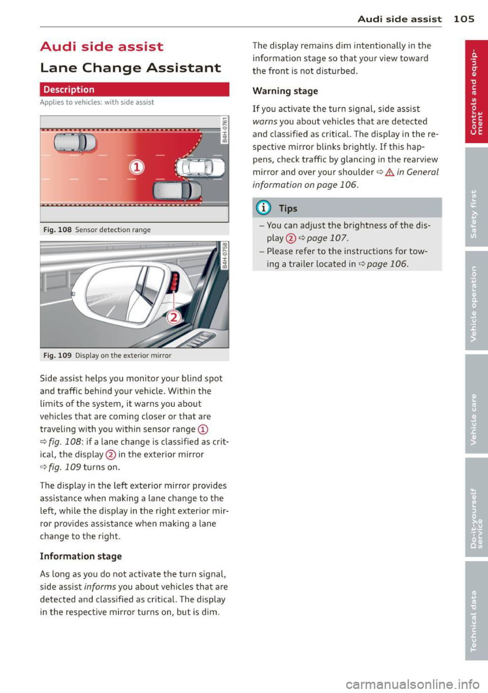
Fig . 108 Sensor detection range
Fig . 109 Disp lay on the exterior mirror
Side assist he lps you monitor your blind spot
and traffic behind your veh icle. W ith in the
limits of the system, it warns you about
vehicles that are coming closer or that are
traveling w ith you within sensor ra nge
(D
c::, fig . 108: if a lane change is class ified as crit
ical, the display @ in the exterior mirror
c::> fig. 109 turns on.
The display in the left exterior mirror provides
assistance when making a lane change to t he
l eft, while the display in the right exter ior mir
r or p rov ides assistance when making a lane
change to the right.
Information stage
As long as you do not activate the turn signal,
side assist
informs you about vehicles that are
detected and class ified as crit ical. The display
i n the respec tive mirro r turns o n, but is d im .
Aud i side assist 105
The display remains d im intentionally in the
information stage so that your view toward
the front is not disturbed .
Warning st age
If you activate the turn signal, s ide assist
warns you about veh icles that are detected
and classified as critical. The display in the re
spective mirror blinks brightly . If this hap
pens, check traffic by glancing in the rearview
mirror and over your shoulder ¢
A in General
information on page 106.
@ Tips
- You can adjust the brightness of the dis
play @¢
page 107.
-Please refer to the instructions fo r tow
ing a trailer located in¢
page 106.
Page 109 of 318
-Improper reliance on the side assist sys
tem can cause collisions and serious
personal injury:
- Never rely only on side assist when
changing lanes.
- Always check rear view mirrors to make
sure that it is safe to change lanes.
- Side assist cannot detect all vehicles un
der all conditions- danger of accident!
- Please note that side assist indicates
there are approaching vehicles, or
vehicles in your blind spot, only after
your vehicle has reached a driving speed
of at least 19 mph (30 km/h).
- In certain situations, the system may not
function or its function may be limited.
For example:
- if vehicles are approaching or being left
behind very quickly. The display may
not turn on in time.
- in poor weather conditions such as
heavy rain, snow or heavy mist .
- on very wide lanes, in tight curves or if
there is a rise in the road surface .
Vehicles in the adjacent lane may not
be detected because they are outside
of the sensor range.
(D Note
The sensors can be displaced by impacts or
damage to the bumper, wheel housing and
underbody. This can affect the system .
Have your authorized Audi dealer or au
thorized Audi Service Facility check their
function.
(D Tips
- If the window glass in the driver's door
or front passenger's door has been tint
ed, the display in the exterior mirror may be misinterpreted.
- For Declaration of Compliance to United
States FCC and Industry Canada regula
tions
~page 299.
Audi side assist 107
Activating and deactivating
App lies to vehicles: wit h side assist
Fig. 112 Driver 's doo r: Side ass ist button
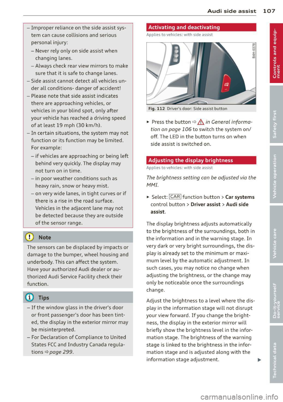
.,. Press the button c> .&. in General informa
tion on page 106
to switch the system on/
off . The LED in the button turns on when
side assist is switched on.
Adjusting the display brightness
App lies to vehicles: wit h side assist
The brightness setting can be adjusted via the
MMI.
.,. Select: I CAR I function button > Car systems
control button
> Driver assist > Audi side
assist .
The display brightness adjusts automatically
to the brightness of the surroundings, both in
the information and in the warning stage . In
very dark or very bright surroundings, the dis
play is already set to the minimum or maxi
mum level by the automatic adjustment. In
such cases, you may notice no change when
adjusting the brightness, or the change may
only be noticeable once the surroundings
change.
Adjust the brightness to a level where the dis
play in the information stage will not disrupt
your view forward.
If you change the bright
ness, the display in the exterior mirror will
briefly show the brightness leve l in the infor
mation stage. The brightness of the warning
stage is linked to the brightness in the infor
mation stage and is adjusted along with the
information stage adjustment .