instrument cluster AUDI S8 2015 Owners Manual
[x] Cancel search | Manufacturer: AUDI, Model Year: 2015, Model line: S8, Model: AUDI S8 2015Pages: 312, PDF Size: 79.18 MB
Page 11 of 312
,....,
N ,....,
N
0 J:
'SI: ,...., \!) 1.1'1 ,...., 1.1'1 ,....,
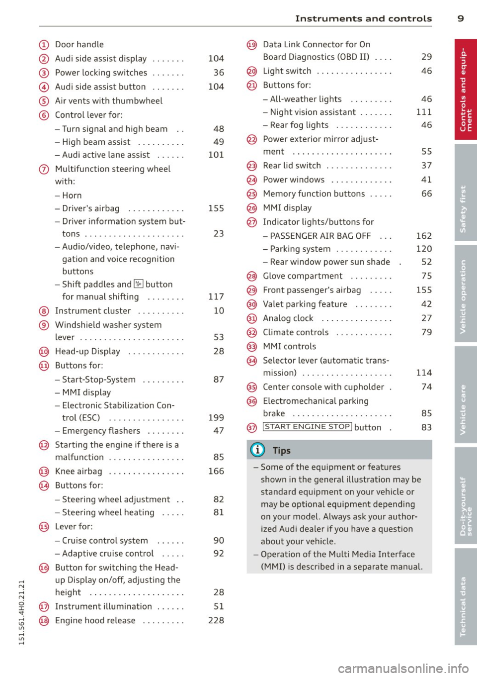
(!) Door handle
@
®
©
®
®
Audi side assist d isplay
Power locking sw itches
Audi side assist button . ... .. .
A ir vents with thumbwheel
Control leve r for :
- Turn signal and high beam
- High beam assist .... ... .. .
- Audi active lane assist ... .. .
(J) Mul tif unction steering wheel
with :
- Horn
- Driver's airbag ....... .. .. .
- Drive r information system but-
tons . ................ ... .
- Audio/video, telephone, navi
gation and vo ice recognition
buttons
- Shift paddles and
lil butto n
for manual shifting ....... .
@ Instrument cluster .. ... .. .. .
® W indshield washer sys tem
lever .. .................. . .
@ H ead-up Display ....... .. .. .
@ Buttons for:
- Start-Stop-System
-MMI display
- Electronic Stab iliza tion Con-
trol (ESC) ............ ... .
- Eme rgency flashers ... .. .. .
@ Starting the eng ine if the re is a
malfunction .... ..... .. .... .
@ Knee airbag . ....... ... .. .. .
@ Buttons for :
- Stee ring wheel adjustment ..
- Stee ring wheel heat ing .. .. .
@ Leverfor:
- Cru ise cont rol system
- Adaptive cruise control .. .. .
@ Bu tton for switch ing the Head
up Disp lay on/off, adj usting the
height . ... ... ..... ... .. .. .
@ Instrument illum in ation . .. .. .
@ Eng ine hood re lease .... .. .. .
104
36
104
48
49
10 1
15 5
23
117
10
53
28
87
199
47
85
166
82
81
90
92
28
51
228
In strument s and control s 9
@) Data Link Connector for On
Board Diagnostics (OBD II)
@ Light sw itch ... .. . .. ... ... . .
@ B uttons for :
- All-weather lights
- Night v ision assistant .... .. .
- Rear fog lights .. .. .. ..... .
@ Power exterior m irror adjust-
ment .. .. .. .. .. . ... ...... .
@ Rear lid switch . .. . ... ...... .
@ Power w indows . .. .. ... .... .
@ Memory function buttons .... .
@) MMI display
@ Indicator lights/buttons for
- PASSENG ER AIR BAG OFF
- Parking system ........... .
- Rear w indow power sun shade
@ G love compar tment .. ...... .
@ Front passenger's airbag .... .
@ Valet pa rking feature ....... .
@ Analog clock .. .. . ... ...... .
@
@
Climate controls
MMI controls
@ Se lector lever (a utomat ic trans-
mission) .. .. .. .... .... .... .
@ Center console w ith cupholder
@ E lectromechanical parking
brake . ... .... .. . .. .. ..... .
@ I START ENGIN E STOPI button
Q) Tips
29
46
46
111
46
55
37
41
66
162
120
52
75
155
42
27
79
1 14
74
85
83
- Some of the equipment or features shown in the genera l illustration may be
standard equ ipment on your vehicle or
may be opt ional equ ipment depending
on your mod el. Always ask your author
ized Aud i dea le r i f you have a quest ion
abou t your vehi cle.
- Ope rat ion of the Multi Med ia Interface
(MMI) is described in a separa te manua l.
Page 12 of 312
10 Instruments and warning/indicator lights
Instruments and warning/indicator Lights
Instruments
Instrument cluster and controls
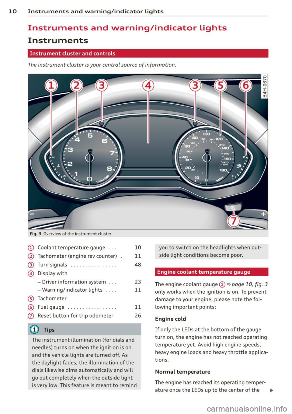
The instrument cluster is your central source of information.
Fig. 3 Overview of th e instr ume nt cluster
(!) Coolan t tempera ture gauge ...
@ Tachometer (engine rev counter)
® Turn signals ............. .. .
© D isp lay with
- Driver information system ...
- Warning/ind icator lights
® Tachom eter
® F uel gauge .... ..... ... ... . .
0 Reset b utton for trip odometer
(D Tips
1 0
11
48
23
11
1 1
26
The instrument illumination (for dia ls and
needles) t urns on when the ignition is on
a nd the vehicle lights are tur ned off. As
the daylight fades, the illumination of t he
dia ls likewise dims automatica lly and w ill
go o ut comple tely when the o utsi de light
i s very low. Th is feature is meant t o rem ind you
to sw itch on the head ligh ts when o ut
s id e light condi tions become poor .
Engine coolant temperature gauge
The engine coolant gauge (!) ¢ poge 10, fig. 3
only works when the ignition is on. To prevent
damage to your engine, please note the fol
lowing important po ints:
Engine cold
If only the LEDs at the bottom of the gauge
turn o n, the engine has not reached operating
temperature yet. Avoid hig h engine speeds,
heavy engine loads and heavy throttle applica
tions .
Normal temp erature
The eng ine has reached its operating temper-
at ure once the LEDs up to the center of the .,.
Page 13 of 312
,....,
N ,....,
N
0 J: 'SI" ,...., \!) ..,.,
,...., ..,., ,....,
Instrument s and warnin g/indic ator ligh ts 11
gauge turn on under normal d riving condi
tions . The LEDs higher up may turn on when
the eng ine is under heavy load or the exter ior
temperature is high . This is no need to worry
as long as the. warning light in the instru
ment cluster does not illuminate . If the LEDs
in the upper area of the display and the ind ica
tor light . in the instrument cluster d isplay
turn on, the coolant temperature is too high
¢page 15.
A WARNING
-Always observe the warning in
~ page 228, Working in the engine
compartment,
before opening the hood
and checking the engine coolant level.
- Never open the engine hood if you see or
hear steam, or if you see engine coolant
dr ipping from the engine compartment.
You could burn yourself. Let the engine
cool off first so that you cannot hear or
see any steam or engine coolant.
(D Note
- Mo unt ing additional lights or accessories
in front of the a ir inlets reduces the cool
i ng effect of the rad iator . At h igh outside
temperatures or high eng ine load, the
engine co uld overheat.
- The front spo ile r has been designed to
properly distrib ute the cooling air when
the veh icle is moving. If the spoiler is
damaged, this cou ld red uce the cooling
effect and t he engine co uld the n over
heat . Ask you r aut ho rized Aud i dea le r for
ass istance.
Tachometer (engine rev counter)
The tachometer indicates the engine RPM
(revolutions per minutes).
If engine R PM drops be low 1,500, you should
downshift to the next lower gear. The red a rea
at the end of the sca le ind icates maxim um
perm iss ible engine RPM after the break-in pe
riod. Before reaching th is area, move these
lector lever to position "D (Drive)" or ease
your foot off the accelerator pedal.
@ Note
The tachometer need le should only briefly
be in the red zone: yo u could damage your
engine! The beg inning of the red zone var
i es dependi ng on the engine.
@ For the sake of the environment
Upsh ifting early saves fuel and reduces en
gine noise.
Fuel gauge
The fuel gauge only works when the ignition is
o n.
If the fue l level drops below 4 gallons (15
l ite rs), the bottom LE D tu rns red and the indi
cator light
tD turns on¢ page 21. The bot
tom LED b link s red when the fue l level is very
l ow .
The possible range based on the current fuel
level is shown in tab@~
page 23, fig. 4.
(D Note
Never run the ta nk complet ely dry. An ir
regular supply of f uel can cause engine
misfiring and fuel cou ld enter the exha ust
system. The cata lytic converter could t hen
overheat and be damaged.
Warning/indicator lights
Description
T he ind ic a tor lights in the ins trument clus ter
blink or tur n on. They indica te fu nct ions or
malfunctions ¢
,&.
Messages may appea r with some indicato r
li ghts. A warning signal will sound at the
same t ime. The indica tor lights an d messages
in the center of the displays may be rep laced
by other disp lays. To show t hem again, select
the tab for ind icator lights and messages us
ing the multifunction steering whee l
¢
page 23. If there are several malfunc
tions, you can display them one at a time us- ing the thumbwheel. ..,.
Page 21 of 312
,....,
N ,....,
N
0 J:
'SI: ,...., \!) ..,.,
,...., ..,., ,....,
Instruments and warning/indicator lights 19
If the fl indicator light turns on, ESC was re
stricted using the
[fil button¢ page 197.
Stabilization control (ESC/ABS): Fault! See
owner's manual
If the: G1 indicator light and the ABS indicator
light
tll1 (USA models) I ii] (Canada models)
turn on and the message appears, the ABS or
e lectronic differential lock is ma lf u nction ing.
This a lso causes the ESC to malfunction . The
brakes sti ll function with their normal power,
but ABS is not act ive .
Drive to your authorized Aud i dea ler or quali
fied workshop immediately to have the mal
function corrected.
A WARNING
If the . (USA models) . (Canada mod
els) brake system indicator light turns on
together with the ABS and ESC indicator
lights, the ABS/ESC regulating function
may have failed. Functions that stabilize
the vehicle are no longer avai lab le. This
could cause the vehicle to swerve and in
crease the risk of sliding. Drive carefully to
the nearest authorized Audi dealer or oth
er qualified workshop and have the mal
function corrected .
(D Tips
For additional information on ESC and
ABS, refer to¢
page 197.
ABS!( @)) Anti-lock braking system (ABS)
This warning/indicator light monitors the ABS
and the electronic differential lock (EDL).
The warning/ind icator light tll1 (USA mod-
e ls)
;tlJ (Canada models) will come on for a
few seconds when the ignition is switched on.
The light will go out after an automatic check
sequence is completed.
There is a malfunction in the ABS when:
- T he warning/indicator light does not illumi
nate when you switch the ignition on. -
The warning/indicator light does not go out
after a few seconds .
- The warning/indicator light il luminates
while driving.
T he ESC indicator lig ht also illuminates if
there is a malfunction in the ABS. The mes
sage
Stabilization control (ESC/ABS) Fault!
See owner's manual
also appears in the in
strument cluster display and a warning tone
sounds.
The brake system will still respond even
without the assistance of the ABS system.
See your authorized Audi dealer as soon as
possible to restore full braking performance.
For more information regarding the ABS
¢pag e 197.
Malfunction in the brake system
If the brake warning light¢ page 14 and the
ABS warning illuminate
together there may be
a malfunction in the ABS, and there may a lso
be a malfunct ion in the brake system itself
¢.&. .The ABS will not work and you will no
tice a change in braking response and per
formance.
In the event of a malfunction in the brake
system
the warning/indicator light . (USA
models) . (Canada models) in the instru
ment cluster flashes ¢
page 14.
Malfunction in the electronic differential
lock (EDL)
The EDL works together with the ABS. The
ABS warning light will come on if there is a
malfu nction in the EDL system ¢
page 197.
See your authorized Audi dealer as soon as
poss ible.
A WARNING
-
-If the tll1 (USA models) ;tl] (Canada
models) warning light does not go out,
or if it comes on while dr iving, the ABS
system is not working properly. The vehi
cle can then be stopped only w ith the
standard brakes (without ABS). You w ill
not have the protect ion ABS provides. ..,.
Page 22 of 312
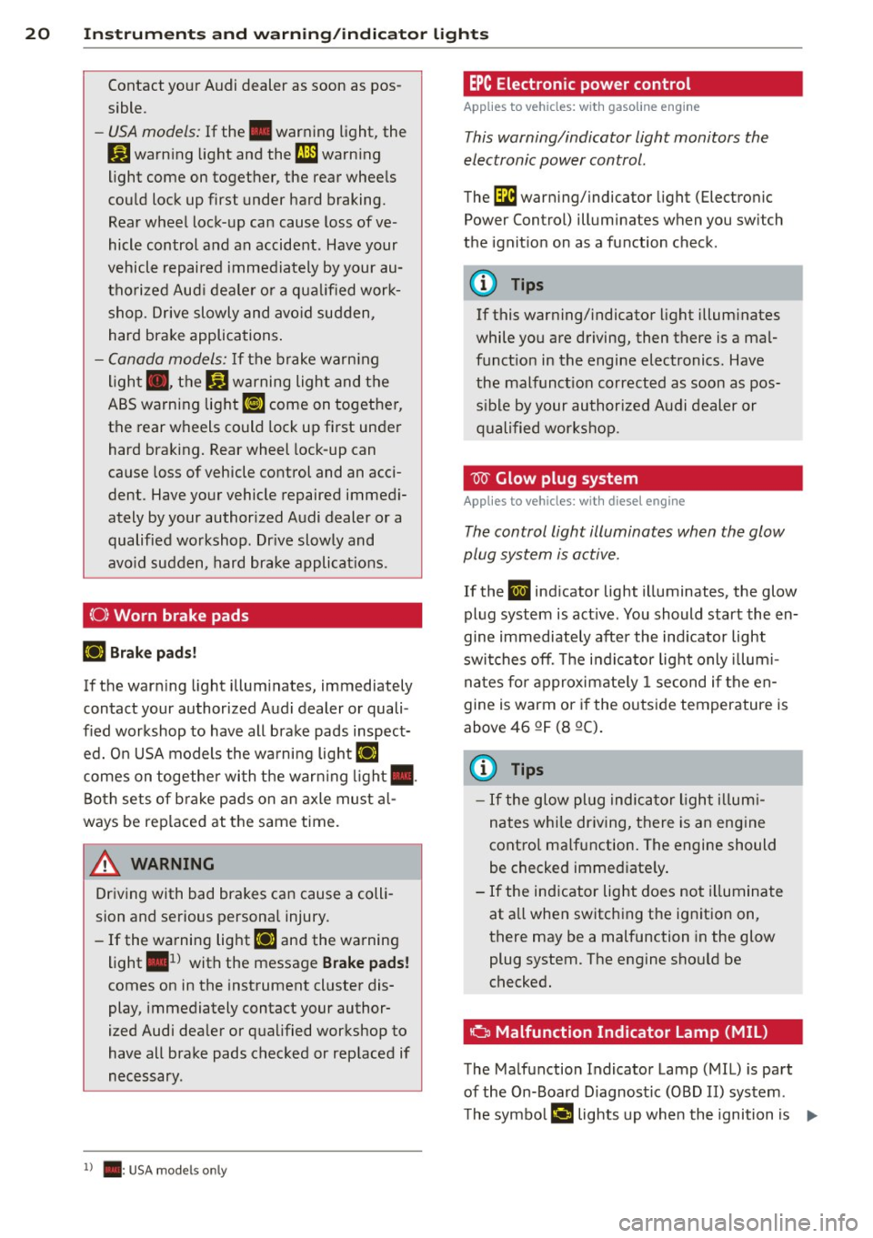
20 Instrum ent s a nd w arn in g/i ndic ato r light s
Contact your Audi dealer as soon as pos
sible.
-USA models: If the . war ning light, the
DJ warn ing light and the fi1 warning
light come on together, the rear wheels
could lock up first under hard braking.
Rear wheel lock-up can cause loss of ve
hicle control and an accident. Have your
vehicle repaired immediately by your au
thorized Aud i deale r or a qua lified wor k
shop. Drive slowly and avo id sudden,
hard brake applications .
-Canada models: If the brake warn ing
light ., the
Ji) warning light and the
ABS warning light
[ill come on together,
the rear wheels could lock up first unde r
hard braking. Rear wheel lock-up can
cause loss of vehicle control and an acci
dent. Have your vehicle repaired immed i
ately by your authorized Audi dealer or a
qualified wo rkshop. Dr ive slowly and
avo id sudden, hard brake applicat ions.
(0) Worn brake pads
Ei'I Brak e pa ds!
If the warn ing light illum inates, immediately
contact your authorized Audi dealer or quali
fied workshop to have all brake pads inspect
ed. O n USA models the wa rning light
Ei'I
comes on together with t he warn ing light •.
Both sets of b ra ke pads on an axle must a l
ways be rep laced at the same time.
A WARNING
Dr iv ing with bad brakes can cause a colli
sion and serious personal injury.
- If the wa rning light
Ei'I and the warning
light
. ll with the message Brake pads!
comes on in the instrument cluster dis
play, immediately contact your author
ized Audi dea ler or qualified workshop to
have all brake pads checked or rep laced if
necessary.
l ) . : USA mode ls on ly
EPC Electronic power control
Applies to veh icles: w ith gasoline engine
This warning/indicator light monitors the
electronic power control .
The Di warning/ indicator light (Electron ic
Power Control) illuminates when you sw itch
the ignit ion on as a function check.
(D Tips
If this warning/ indicator light illum inates
while you are driving, then there is a mal
funct ion in the engine electronics. Have
the malfunct ion corrected as soon as pos
s ible by your authorized Audi dealer or
qualified workshop.
W Glow plug system
Applies to veh icles: w ith diesel engine
The control light illuminates when the glow
plug system is active.
If the II ind icator light illuminates, the glow
plug system is act ive. You should start the en
gine immediately after the ind icator light
swi tches off. The ind icator lig ht only illum i
na tes for approximate ly 1 second if the en
gine is warm or if the outs ide temperature is
above 46 QF (8 QC).
(D Tips
-If the glow plug indicator l ight i llum i
nates while dr iving, there is an eng ine
cont ro l ma lfunction. The engine should
be checked immed iate ly .
- If the ind icator light does not illuminate
at a ll when switch ing the ignit ion on,
there may be a malfunction in the glow
plug system. The engine should be
checked.
' o Malfunction Indicator Lamp (MIL)
The Ma lfunction Indicator Lamp ( MIL) is part
of the On-Board Diagnost ic (080 II) system.
T he symbo l¢..,, lights up whe n the ignition is ...
Page 25 of 312

Instrument s and warning /indicator lights 23
I--: Sport differential
IIJ Sport differential: system fault
There is a malfunction with the sport differen
tial.
Drive to your authorized Audi dea ler immedi
ately to have the malfunction corrected.
IIJ Sport differential: overheating
The transmission temperature has increased
sign ificantly due to the sporty dr iving manner .
D rive in a less sporty manner until the tem
perature returns to the normal range and the
indicato r light switches of .
.&_ WARNING
-
Contact your authorized Audi dealer or a
qualified workshop if the sport different ial
is faulty or ma lfunctioning. The repa ir
must be performed by trained personnel
using the correct oil in order to ensure
safety.
¢ Q Turn signals
The indicator light blinks when you use either
turn signal.
Whenever you use the left Nor the right a
turn signal, the indicator light blinks. When
you use the emergency flashers, both indica
tor lights flash .
If one of the turn signal light bulbs burn out,
the turn signal will blink tw ice as fast as nor
mal. Carefully drive to your authorized Audi
dealer immediately to have the malfunct ion
corrected. The indicator light does not indi
cate a malfunction if a turn signa l on the trail
er or on the vehicle fails in trailer towing
mode.
(D Tips
For more information on the turn signals,
refer to¢
page 48.
Driver information
display
Overv iew
Fig . 4 Drive r info rmation system in the inst rument
cluster
Fig. 5 Display: examp le of the info rmat ion lin e
The driver information system contains infor
mation @ that is displayed on tabs @
¢ fig. 4. The following content is possible de
pending on vehicle equipment:
@
®
Tab Content
1 Vehicle
functions :
On-board computer ¢ page 25
Efficiency program*¢ page 26
Digital speedometer
Cruise control*¢
page 90
Adaptive cruise control and braking
guard* ¢
page 92
Audi active lane ass ist* <=> page 101
Display darkened ...
Page 28 of 312

26 Instruments and warning /indicator lights
Efficiency program
App lies to vehicles: with efficiency program
Fig . 9 Tri p com puter: ot her equipment
Fig. 10 D isplay: example of a f uel eco no m y message
The effic iency program can help you to use
l ess fuel.
It shows other eq uipment influenc
ing consumpt ion and fue l economy messages
p rov ide tips f or efficient driv ing . The efficiency
prog ram uses distance a nd consumption data
from tr ip compute r
1.
To display the efficiency program, ca ll up Ve
hicle functions
and select the menu option
Efficiency program .
Other equipment
Other equipment that is currently affecting
fuel consumption is listed in t he v iew
Con
sumer .
The display shows up to three other
items of equipment @¢
fig. 9. The equip
ment us ing the most fuel is listed f irst . If
mo re than three it ems using fue l ar e swit ch ed
on, the eq uip ment th at is cur ren tly using the
most fuel is d isp laye d.
A scale @also shows the cu rrent total con
sumpt ion of all other equ ipme nt.
Fuel economy messages
F ue l economy messages are disp layed when
fue l consumption is increased by certain con- di
tions ¢
fig. 10 . If you follow these fuel
economy messages, you can reduce you r vehi
cle's consumpt io n of fuel. The messages ap
pear automatically and are on ly disp layed in
t h e efficiency program . The f uel economy
messages tu rn
off automatically after a cer
ta in period of ti me.
To turn an economy message
off i mmediately
after it appears, press any button on t he mul
t if u nct ion steer ing whee l.
@ Tips
- If the data are deleted in the efficiency
program , those values a re a lso reset i n
t rip computer.
- Once you have turned a fuel economy
message
off, it will on ly appear agai n af
ter you turn the ig nition on again .
- The f uel economy messages are not dis
played in every instance, but rather in in
t ervals over a period of time .
Odometer
Fig. 11 Instrume nt cluster O do m eter a nd r eset button
The odometer shows you how many m iles
(k ilomete rs) you have drive n. You can switch
the d isplay from miles to ki lometers and v ice
versa via the MMI.
Upper odometer
The trip odometer shows the distance driven
since it was last reset . It can be used to meas
u re s hort dista nces . The last digit indicates
1/10 of a mile (100 meters).
You can reset the trip odometer to zero by pressing the Reset button~-
Page 29 of 312

Instruments and warning/indicator lights 2 7
Lower odometer
The lower odometer shows the total number
of miles (kilometers) driven.
Malfunction message
If there is a malfunction in the instrument
cluster ,
DEF will appear in the trip odometer
display area. Contact your authorized Audi
dealer to have the problem corrected.
Time and date display
Fig. 12 Center console : analog cloc k
The date and time are shown in the instru
ment cluster display ¢
page 23, fig. 4. There
is also an analog clock in the center console
¢fig. 12.
When you open the driver's door, the date and
time appear in the instrument cluster display
for 30 seconds. When the ignition is switched
on, the time is always displayed in the status
line © regardless of the current display.
You can set the time on both clocks and the
date display in the MMI. Refer to the MMI
owner's manual for instructions.
Service interval display
The service interval display reminds you when
your next service is due .
Fig. 13 Instrume nt cluster: Serv ice interva l dis play
The schedule for the next oil change or inspec
tion is calculated automatically and displayed
accordingly. The display works in two stages:
Service reminder
30 days before the next service is due, a serv
ice reminder appears in the display when you
switch the ignition on¢
fig. 13.
After about 5 seconds the display switches
back to normal. The distance and time re
maining are updated each time the ignition is
switched on until the date due for service is
reached.
Service due
When the due date for service is reached, the
message
Service due! appears in the instru
ment cluster immediately after you switch the
ignition on. Additionally, a warning tone
sounds. After about 5 seconds the display
switches back to normal.
Calling up the service schedules
If or when an oil change or inspection is due,
can be shown in the MMI display by selecting
the service interval display in the car menu.
Select the
I CAR I function button > Car sys
tems control button > Servicing & checks >
Service interval displays .
Resetting the service interval display
Your authorized Audi dealer will reset the cor
responding service schedule after performing ..,_
Page 34 of 312

32 Opening and clo sing
Remov ing the mechanical key
Fig. 19 Remote control master key : removing the me
chanical key
.. Press the release button@r=>.> fig. 19.
• Pull the mecha nica l key @ out of the master
key.
Using the mechan ica l key, you can:
- lock and unlock* the storage compartment
on the passenger's side c::>
page 75.
-lock and unlock the vehicle manually
<=>page 36.
-lock the front and rear passenger doors me
chanically
c::> page 37.
- unlock the luggage compartment lid man
ually
c::> page 40.
Check light and battery in the master
key
Fig. 20 Remote master key: Removing the battery
holder
Check light in the master ke y
The check light@c::> fig. 20 in the master key
prov ides informat ion about d ifferent cond i
tions.
• The check light turns on briefly once when a
button is pressed, and dur ing an "inquiry"
by the convenience key system. •
If the check light does not come on, the bat
tery is dead and has to be replaced. In addi
tion, when the battery is dead the
!I indi
cator light appears in the instrument cluster
display as well as the message
Pl ease
chang e th e ke y b attery .
Ma ster key batter y replacement
• Remove the mechanica l key c::> page 32.
• Press the release button@¢ fig. 20 on the
battery holder and at the same time pull the
battery holder out of the master key in the
direction of the arrow .
.. Install the new battery CR 2032 with the
"+" sign facing down.
.. Push the battery holder carefu lly into the
maste r key.
• Insta ll the mechanical key .
@ For the sake of the environment
Dis p ose of dead batteries prope rly so as
not to poll ute the environment.
{D Tips
The replacement battery mus t be the
same specification as the o rigina l.
Electronic immobilizer
The immobilizer helps to prevent unauthor
ized use of your vehicle .
A computer chip ins ide your key automatically
deact ivates the elect ron ic immobilizer when
the key is ins ide the veh icle. When you remove
the key from the vehicle, the elect ron ic immo
bilizer is au tomatically activa ted once aga in.
& WARNING -
A lways take the key w ith you when you
l eave the vehicle. The key can disarm the
e lectronic engine immobilizer and permit
an una uthorized person to start the engine
and enable operation of the vehicle sys
tems such as power w indow or power sun-
r oof leading to se rious pe rsonal injury.
~
Page 45 of 312

.... N .... N
0 J:
"". .... I.O
"' ....
"' ....
.. Leave the master key with the service per
sonnel for park ing and keep the mechanica l
key w ith you.
When the "valet parking" feature is activated:
- the un locking button for the luggage com
partment lid~ in the d river's door is inac
t ive
- the button~ on the master key is inactive
- the opening handle in the luggage compart-
ment lid is inactive .
The vehicle can be driven and locked and un locked with the master key . Access to the lug
gage compartment is blocked .
When the valet parking function is switched on, the message
Valet parking activated ap
pears in the instrument cluster display when
you switch the ign it ion on .
Sliding/tilting sunroof
Operation
Fig. 37 Sectio n of the headliner: Slid ing/t ilting sunroof
b utto n
@ Tilting and sliding
.. To tilt the sunroof complete ly, press the
switch briefly to the second leve l¢
fig. 3 7
briefly.
.. To close the sunroof completely, pull the
switch brief ly to the second leve l¢ ,&. .
.. To select a n intermediate position, press/
pull the switch to the first level until the de
s ir ed pos it ion is reached .
@ Opening and closing
.. To open the sunroof completely, slide the
button back briefly to the second level.
Opening and closing 43
.. To close the sunroof completely, slide the
button forward briefly to the second level
¢ ,&. .
.. To select a partially open position, slide the
button forward/back to the first level until
the roof reaches the desired position .
A wind deflector integrated into the sliding/
t ilting sunroof adapts automatically to the
speed and sunroof pos ition . This reduces wind
noise to a minimum in all sunroof positions .
You can still close or open the sunroof for up
to ten minutes after you have switched the ig nition off . The sw itch is deactivated once the
driver's or front passenger's door is opened .
Solar protection
The solar protection opens automatically
when the sunroof opens.
Vehicles with a glass pane l sunroof : the sun
shade can be opened and closed by hand
when the sunroof is closed.
Vehicles with a solar pane l sunroof*: the
closed sunshade opens automatically when
the sunroof opens.
A WARNING
-Pay careful attention when closing the
sliding/tilt ing sunroof -otherwise serious
injury could result! Always take the key
with you when leav ing the veh icle .
(D Note
-
Always close your sliding/tilting sunroof
when leaving your vehicle. Sudden rain can
cause damage to the interior equipment of
your vehicle, particularly the electronic equipment .
@ Tips
-Information regarding the so lar roof*
¢page 81 .
-The sliding/tilt ing sunroof w ill only open
at temperatures above -4 °F
(-20 °() .