steering wheel AUDI TT ROADSTER 2008 Owners Manual
[x] Cancel search | Manufacturer: AUDI, Model Year: 2008, Model line: TT ROADSTER, Model: AUDI TT ROADSTER 2008Pages: 316, PDF Size: 70.1 MB
Page 13 of 316
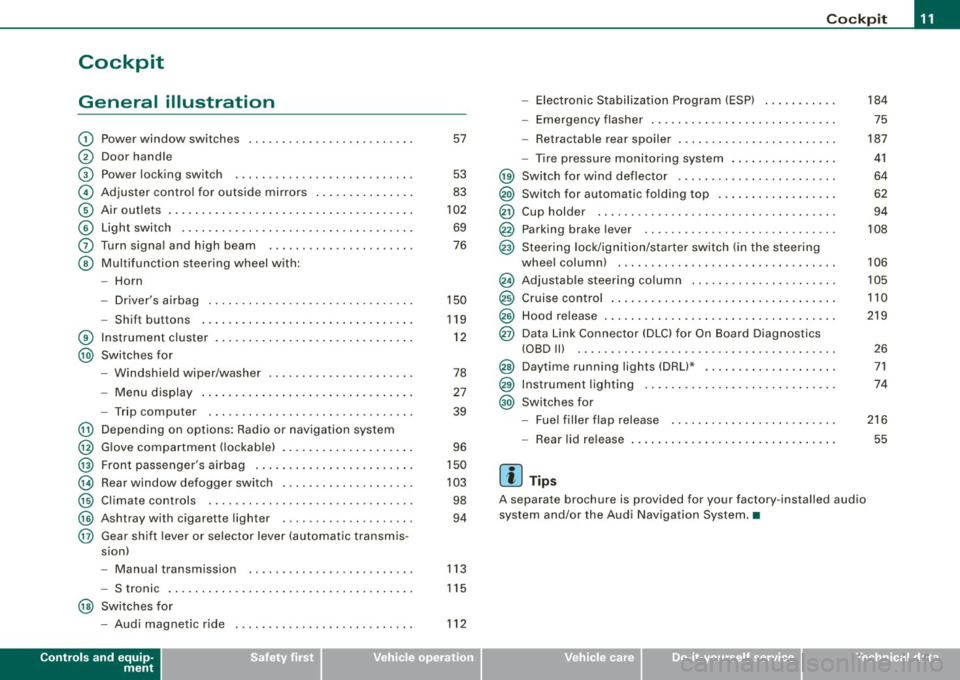
Cockpit
General illustration
G)
0
©
©
©
©
0
©
®
@
@
@
@
@
@
@
@
Power window switches
Door handle
Pow er lo cking switc h
Adjus te r contro l fo r ou tsid e mirro rs ...... .... ... . .
Air outlets ..... .. . ..... .... .... .. . .... .. . ..... .
Light switch .. ...... .... ... .... .... .... .... ... .
Turn signa l and high beam
Multifunc tion steering wheel with:
- Horn
- Driver's a irbag .... .... ... .... .... .... .... ... .
- Shift b uttons ... .. .... ... .... .... .... .... ... .
Instr um en t cluster . ...... ... .... .. ...... .. .. ... .
Switches for
- Windshield wipe r/wash er ... .... .. ....... .. ... .
- Menu d isplay ...... ... .. .. .... .... .... ... ... .
- Trip computer ..... .. .... .... ...... ....... .. .
Depending on options : Radio or navigation sys tem
G love compa rtmen t (loc kab le) ... .. .. .. ... .... ... .
Front passenger 's airbag .. ...... .. . .... .. .. .... .
Rear window defogger switch .... ..... .. .... .... .
Climate controls ..... .. .... .... ..... .. ... ... .. .
Ashtray wi th cigare tte lighter ....... ............ .
Gear sh ift l ever or s elector lever (automatic transmis -
sion) 57
53
83
102
69
76
150
119
1 2
78
27
39
96
150
10 3
98
94
- Manual transm ission . . . . . . . . . . . . . . . . . . . . . . . . . 113
- S tronic . . . . . . . . . . . . . . . . . . . . . . . . . . . . . . . . . . . . . 115
@ Switches for
- Aud i magnetic r ide
Controls and equip
ment
112
Co ckpit
- Electronic Stabilization Program (ESP) . .... .. ... .
- Emerge ncy flasher ... .. .. .. .... .... .... .. . ... .
- Retractab le r ear spoiler .... ...... .... .... .... . .
- Tire pressure mon itor ing system ..... .... .. . ... .
@ Sw itc h f or wind deflector .... .. ..... .. .... ... ... .
@) Switch for automatic folding top ..... .. .... ... ... .
@ Cup hold er ....... .. .. .. .... .... ....... ....... .
@ Parking brak e le ver ... .... ..... .. .... .... ..... . .
@ S teeri ng lock/igniti on/sta rter sw itch (in t he s teer ing
whee l column) ... .... ... ... ... .. .... .... ...... .
@ Adjus tab le steering co lu m n .. ...... ..... ... ... .. .
@ Cruise contro l .... ... .... .... .... .... .... ... ... .
@ Hood release ... .. .. .. ..... .. .... .... .... ...... .
@ Data Link Connect or (DLC) for On Boa rd Diag nostics
(OBD Ill .... ... .. ...... .... ... .... ... .. ... .... .
@ Daytim e running l ights (DRU* .... .... .... .... ... .
@ Instrumen t lighting ...... .... .... .... ... .... ... .
@ Switc hes f or
- Fue l filler flap release .... .. .... .... .... ... ... .
- Rea r lid r elease
[ i ] Tip s
A separate brochure is provided for your factory -insta lled audio
system and/or the Aud i Nav igation System .•
I • •
184
75
187
41
64
62
94
108
106
105
110
219
2 6
71
74
216
55
Page 23 of 316
Malfunction in the brak e system
USA models: If bot h, th e BRAKE wa rn ing l igh t and the .... rs warning
light come on~
page 20when the parking brake is released, there
may be a ma lfunction in the ABS, and there may a ls o be a malfunc
t ion in the brake sys tem it se lf~
&-
Canada models: If both, the brake warning light (Q)) and the ABS
wa rning light c ome on~
page 20w hen the parking bra ke i s
released, there may be a ma lfunction in the ABS, and there may a lso
b e a ma lf un ction in the brake sys tem itsel f~
& -
Malfunction in the electronic differential lock (EDL )
The two sys te m s EDL and ABS wor k together. The ~ warning ligh t
wi ll come on if there is a malfunct ion in the EDL system~
page 186.
See your au thorize d Aud i dea le r as soon as poss ibl e.
& WARNING
• If the P • warning light does not go out, or if it comes on while
driving , the ABS system is not working properly . The vehicle can
then be stopped only with the brakes operating without ABS support . You will not have the protection ABS provides . Contact
your Audi dealer as soon as possible .
• USA models : If both, the BRAKE warning light and the
warning light come on at the same time , the rear wheels could
lock up first under hard braking . Lock-up of the rear wheel brakes
can cause loss of vehicle control and an accident. Have your
vehi cle repaired immediately by your authorized Audi dealer or a
qualified workshop. Drive slowly and avoid sudden, hard brake
application .
• Canada models: If both, the brake warning light (Cl) and the ABS
warning light ""' come on at the same time , the rear wheels could
lock up first under hard braking. Lock -up of the rear wheel brakes
can cause loss of vehicle control and an accident. Have your
vehicle repaired immediately by your authorized Audi dealer or a qualified workshop. Drive slowly and avoid sudden , hard brake
appli cation •
Controls and equip
ment
Instruments and warning /indi cator lights
Electro-mechanical power assist t / @
If the indicator light il luminates while you are driving, there is a
m alfunc tion in th e electro -m echa nical s teering. If the i ndica to r lig ht
is show ing ~, there may be a reduction in power steering ass ist. If
t he indi cator l ig ht is sh owing ~' the re may be a total loss o f pow er
steerin g assist . T he steerin g must be inspected immediately by a
q u alified works h op ~
6,. W ith the engine not ru nning (e.g. w hen
th e car is b eing tow ed), there is a lso no power assist avai lable .
& WARNING
If there is a malfunction , the indicator light for the electro -mechan
ical power assist illuminates . Seek professional assistance. •
I • •
Page 78 of 316
Clear vision
• your vehicle is being towed by a tow truck or if you are towing
another vehicle behind you. •
Turn signals -¢ ¢ and high beam ~D lever
The lever on the left side of the steering column is used to
operate the turn signals and the high beam as well as the
headlight flasher.
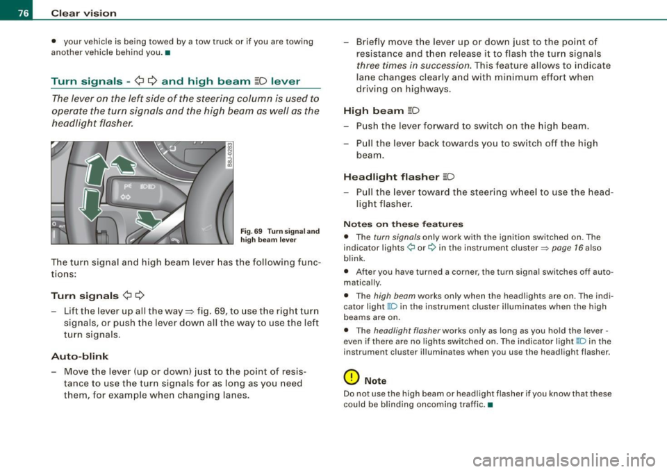
Fig. 69 Turn signa l and
high beam leve r
The turn signal and high beam lever has the following func
tions:
Turn signals ¢ Q
- Lift the lever up all the way ~ fig. 69, to use the right turn
signals, or push the lever down all the way to use the left
turn signals .
Auto-blink
-Move the lever (up or down) just to the point of resis
tance to use the turn signals for as long as you need
them, for example when changing lanes. - Briefly
move the lever up or down just to the point of
resistance and then release it to flash the turn signals
three times in succession. This feature allows to indicate
lane changes clearly and with minimum effort when
driving on highways.
High beam [D
- Push the lever forward to switch on the high beam.
- Pull the lever back towards you to switch off the high
beam.
Headlight flasher [D
- Pull the lever toward the steering wheel to use the head
light flasher.
Notes on these features
• The turn signals only work with the ignition switched on . The
indicator lights ¢ or¢ in the instrument cluster => page 16 also
blink .
• After you have turned a corner, the turn signal switches off auto
matically.
• The high beam works only when the head lights are on . The indi
cator light ~D in the instrument cluster i lluminates when the high
beams are on.
• The headlight flasher works only as long as you hold the lever -
even if there are no lights switched on. The ind icator light ~D in the
instrument cluster illuminates when you use the headlight flasher .
0 Note
Do not use the high beam or headlight flasher if you know that these
could be blinding oncoming traffic. •
Page 80 of 316
Clear vision
Wiper and washer system
Windshield wiper ~
The windshield wiper lever controls both the windshield
wipers and the washer system.
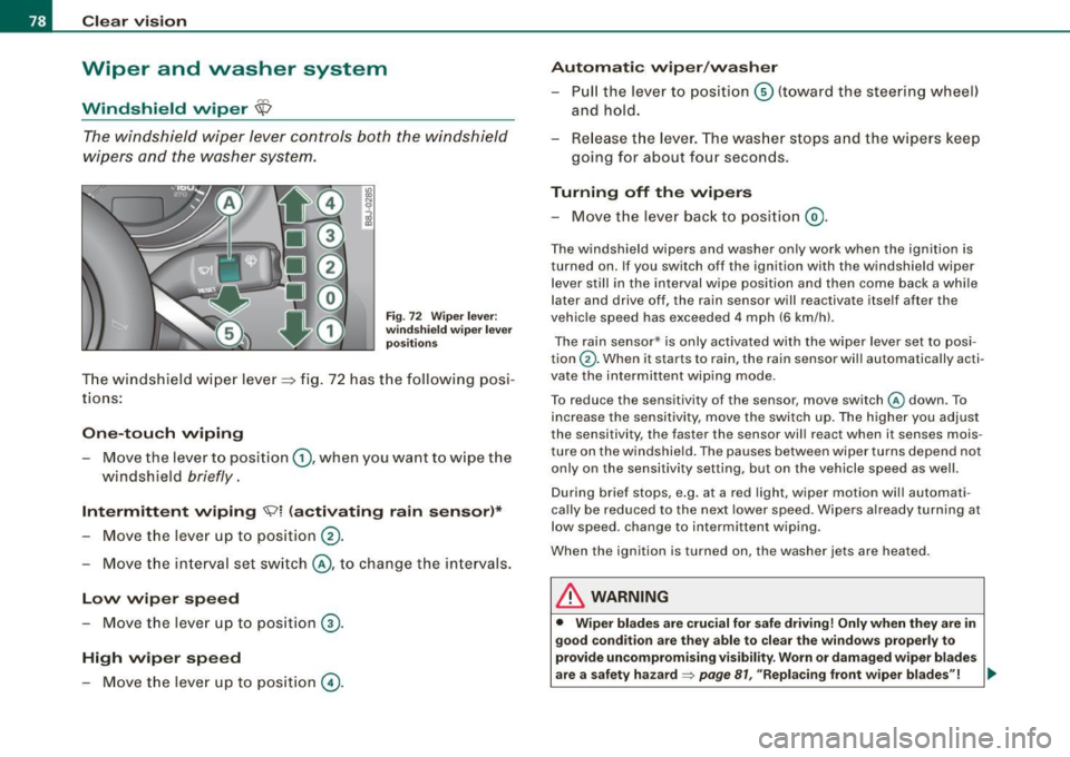
Fig. 72 Wiper lever:
windshield wiper lever
positions
T he windshield wiper lever :::::> fig. 72 has the following posi
tions:
One -touch wiping
Move the lever to position G), when you want to wipe the
windshield
briefly.
Intermittent wiping ~ l (activating rain sensor)*
Move the lever up to position 0-
- Move the interval set switch@, to change the inter vals .
Low wiper speed
-Move the lever up to position ©-
High wiper speed
- Move the lever up to position @.
Automatic wiper/washer
- Pull the lever to position© (toward the steering wheel)
and hold.
- Re lease the lever . The washer stops and the wipers keep
going for about four seconds .
Turning off the wipers
-Move the lever back to position @.
The windshield wipers and washer only work when the ignition is
turned on. If you switch off the ignition with th e windshield wiper
lever still in the interval wipe position and then come back a while
later and drive off, the rain sensor will reactivate itse lf after the
vehic le speed has exceeded 4 mph (6 km/h).
The rain sensor* is only activated with the wiper lever set to posi
tion
G) . When it starts to rain, the rain sensor will automatically acti
vate the intermittent wiping mode.
To reduce the sensitivity of the sensor , move switch
@ down . To
increase the sensitivity , move the switch up. The higher you adjust
the sensi tivity, the faster the sensor will react when it senses mois
ture on the windshield. The pauses between wiper turns depend not
only on the sensitivity setting , but on the vehicle speed as well.
During brief stops , e.g. at a r ed light, wiper mot ion wil l automati
cally be reduced to the next lower speed. Wipers a lready turning at
low speed . change to intermittent wip ing.
When the igni tion is turned on, the washer jets are heated.
& WARNING
• Wiper blades are crucial for safe driving! Only when they are in
good condition are they able to clear the windows properly to
provide uncompromising visibility. Worn or damaged wiper blades
are a safety hazard~
page 81 , "Replacing front wiper blades"! ..,_
Page 89 of 316
Seats and storage
General recommendations
Why is your seat adjustment so important?
The safety belts and the airbag system can only provide
maximum protection if the front seats are correctly
adjusted.
There are various ways of adjusting the front seats to provide safe
and comfortable support for the driver and the front passenger.
Adjust your seat properly so that:
• you can easily and quickly reach all the switches and controls in
the instrument panel
• your body is properly supported thus reducing physical stress
and fatigue
• the safety belts and airbag system can offer maximum protec
tion
~ page 146.
In the following sections, you will see exactly how you can best
adjust your seats.
There are special regulations and instructions for installing a child safety seat on the front passenger's seat. Always heed the informa
tion regarding child safety provided in~
page 168, "Child Safety".
& WARNING
Incorrect seating position of the driver and all other passengers
can result in serious personal injury.
• Always keep your feet on the floor when the vehicle is in motion
- never put your feet on top of the instrument panel, out of the
window or on top of the seat cushion! This applies especially to
the passengers. If your seating position is incorrect you increase
the risk of injury in the case of sudden braking or an accident. If
Controls and equip
ment
Seats and storage
& WARNING (continued)
the airbag inflates and the seating position is incorrect this could
result in personal injury or even death.
• It is important for both the driver and front passenger to keep
a distance of at least 10 inches (25 cml between themselves and
the steering wheel and/or instrument panel. If you're sitting any closer than this, the airbag system cannot protect you properly. In
addition to this, the front seats and head restraints must be
adjusted to your body height so that they can give you maximum
protection.
• Always try to keep as much distance as possible between your
self and the steering wheel or instrument panel.
• Do not adjust the driver's or front passenger's seat while the
vehicle is moving. Your seat may move unexpectedly, causing
sudden loss of vehicle control and personal injury. If you adjust
your seat while the vehicle is moving, you are out of position. •
Driver's seat
The correct seat position is important for safe and relaxed
driving.
We recommend that you adjust the driver's seat in the
following manner:
- Adjust the seat in fore and aft direction so that you can
easily push the pedals to the floor while keeping your
knee slightly bent:::>
& in "Why is your seat adjustment
so important?".
Adjust the seatback so that when you sit with your back against the seatback, you can still grasp the top of the
steering wheel. _..
I • •
Page 107 of 316
___________________________________________________ O _n_ t_h :.... e:.....:. r_:o :.... a:.:. d ..:.:.___,J"'
On the road
Steering
Adjusting the steering wheel column
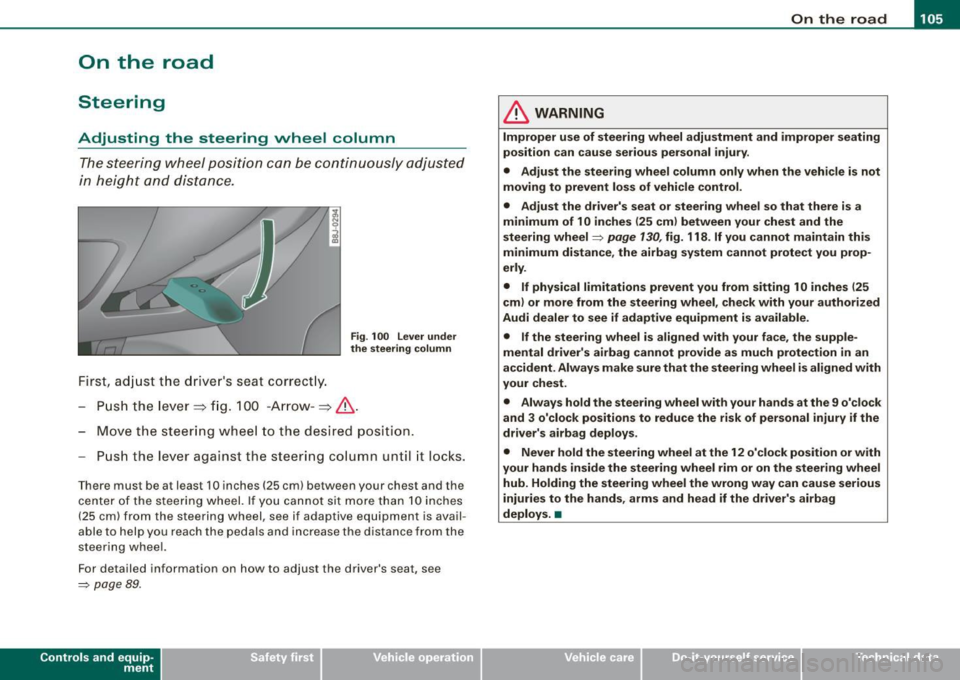
The steering wheel position can be continuously adjusted
in height and distance.
First, adjust the driver's seat correctly.
Fig. 100 Lever under
the steering column
-Push the lever~ fig. 100 -Arrow-~ /.1 .
- Move the steering wheel to the desired position.
Pu sh the lever against the steering column until it locks.
T here must be at least 10 inches (25 cm) between your chest and the
center of the steering wheel. If you cannot sit more than 10 inches
(25 cm) from the steering wheel, see if adaptive equipment is avail
able to help you reach the pedals and increase the distance from the
steering wheel.
For detailed information on how to ad just the driver's seat, see
=> page 89.
Contro ls and eq uip
ment
& WARNING
Improper use of steering wheel adjustment and improper seating
position can cause serious personal injury.
• Adjust the steering wheel column only when the vehicle is not
moving to prevent loss of vehicle control.
• Adjust the driver's seat or steering wheel so that there is a
minimum of 10 inches (25 cm) between your chest and the
steering wheel
=> page 130, fig. 118 . If you cannot maintain this
minimum distance , the airbag system cannot protect you prop
erly .
• If physical limitations prevent you from sitting 10 inches (25
cm) or more from the steering wheel, check with your authorized
Audi dealer to see if adaptive equipment is available.
• If the steering wheel is aligned with your face, the supple
mental driver's airbag cannot provide as much protection in an
accident. Always make sure that the steering wheel is aligned with
your chest .
• Always hold the steering wheel with your hands at the 9 o'clock
and 3 o'clock positions to reduce the risk of personal injury if the
driver's airbag deploys .
• Never hold the steering wheel at the 12 o'clock position or with
your hands inside the steering wheel rim or on the steering wheel
hub . Holding the steering wheel the wrong way can cause serious
injuries to the hands , arms and head if the driver's airbag
deploys .•
Vehicle care
I I irechnical data
Page 108 of 316
• ..__O_ n_ t_h _ e_ r_ o_ a_ d ____________________________________________________ _
Ignition lock and ignition switch
Ignition lock
The igniti on key starts or s tops the eng ine.
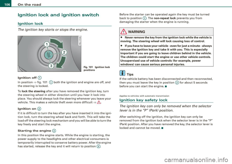
Ignition off G)
Fi g. 1 01 Ign it io n lock
po sition s
In posit ion => fig. 101 G) both the ignition and engine are off, and
t he steering is locked.
To
lo ck the steering after you have removed the ignition key, turn
the steering whee l in either direction until you hear it lock into
place . You should always lock the steering whenever you leave your
vehic le. This makes a vehicle theft even more difficult =>& .
Ignition on 0
If it is difficult to turn the key after you have inserted it into the igni
tion lock, turn the steering wheel back and forth. This will take the
load off the steering lock mechanism and you wil l be able to turn the
key freely and start the engine.
Starting the engine ®
In this position the engine starts . Whi le the engine is starting, the
power supply to the headlights and other electrical consumers is
temporari ly interrupted to conserve battery power . After the engine
has started, release the key and it will return to position
G) .
Before the starter can be operated again the key must be turned
back to posi tion
G) . The non -repeat lock prevents you from
damaging the starter when the engine is running.
& WARNING
• Never remove the key from the ignition lo ck while the veh icle is
moving. The steering wheel will lo ck causing lo ss of control .
• If you have to leave your vehicle -even for just a minute -always
remove the ign ition key and take it with you . This i s especially
i mportant if you are going to l eave children behind in the vehi cle .
The children could start the eng ine or u se other vehi cle control s.
Unsupe rv ised use of vehicle controls (for e xample , power
window s) can cau se serious per sonal injurie s.
[ i ] Tips
If the veh icle ba ttery has been disconnected a nd then reconnected,
then you must leave the key in position
G) for about 5 seconds
bef ore you can start the engine .•
Appl ies to vehicles: with automat ic trans miss io n
Ignition key safety lock
The ig nition ke y can only be rem oved when the selec tor
le ver i s in the "P" (Par k) p osition.
After switching off the ignition, the ignition key can only be
r emoved from the igni tio n lock w hen the se lector leve r is in the "P"
(Park) position . After you have removed the key, the selector lever is
l ocked and cannot be moved. •
Page 111 of 316
_________________________________________________ O .=.:.n.:....: t~h :.::e ::....:.. r.::o :.::a :.:d::...__lfflll
- Wit h a manual transm issi on, engage 1st gea r, or with a n
a utomatic transmission place the se lector lever in P
=> & .
- Remove the ignition key from the ignit io n lock.
Wha t el se you should do wh en parking yo ur v ehi cle on
a n incli ne or d ecline
Turn the steering whee l so that if the vehicle shou ld start to rol l, it
wi ll roll into the curb.
I f you are park ing on a
decline (the front of you r ve hicle facing
downhill) , turn the front wheels to the right so that they poin t
toward the curb .
If you are park ing on an in cline (the font of your vehicle facing
uphill!, turn the front whe els to the left so that they point
away from
the curb .
& WARNING
This is how you can reduce the ri sk of injury when le avi ng your
vehicle .
• Never p ark the vehi cle w here it can come
in cont act w ith dry
gra ss, s pilled fuel or any other flammable mater ial s.
• Never allow anyone -espe cially small ch ildren -to remain
in the
vehicle when it is locked . Locked doors make it more difficult for
re scu ers to ac ce ss the pa ssenger compartment in the e vent of an
emergency . Danger to life!
• Never lea ve childr en un super vis ed in the vehicle . Children
c ould release the parking brake or move the gearsh ift l ever out of
gear . The vehicle could start to r oll away a nd cau se an a ccident .
• No matter what the season i s, the temperature
in a parked
v ehi cle can reach dangerou s level s. •
Controls and equip
ment
Acoustic parking system
A pplies to veh ic les : wit h 4 -ch anne l a cou stic park ass is t
Rear acoustic park assist
Acoustic park assist gives a warning a bout o bstacles
behind the vehicle.
Description
The rear acoustic park assist (4 -channel acoustic park assist) deter
mines the d istance of the vehic le from an obstac le using u ltrasonic
sensors. The sensors are in the rear bumper. The volume and the
pitch of the chimes can be adjusted through the menu display
=> page 27.
The range at which the sensors start to m easure is about :
To the side
Center rear
Acti v atio n
2 feet (0 .60 m)
5 feet (1.60 ml
The pa rking assist is activated when rever se ge ar is engaged . A brief
tone confirms that the system is activated .
Backing up
Distance warning when backing up starts when an obstacle is
detec ted in the range of the park ass ist system . As the distance
decreases, the time interval between the aud ible tones becomes
shorter .
When the distance is less than 1 foot (0.30 m) , the tone becomes
continuous . At this point you should stop backing up.
Please note that low objects a lready signalled by a warning can
disappear from the sys tem's detection range and wil l not continue
t o be signa lled . ..,
I • •
Page 119 of 316
____________________________________________________ T_ r_a _n _ s_ m __ is_ s_ i _o _ n __ ftllll
A ut omat ic selec to r l ever lock <&
The se lector lever is locked in the P and N positions when the igni
tion is on . To move the lever from these positions the driver must
depress the brake pedal. As a reminder to the driver, the fol lowing
warning appears in the instrument cluster display when the selector is in P and N:
A PP LY BRAK E WHEN ENGAGING GEAR WITH VEHIC LE
S TATIONARY
In addition, the symbo l<& for the automat ic selector lever lock illu
minates in the shift gate.
T he selector lever lock is effective only when the vehicle is
stationary and at speeds below 5 km/h . At higher speeds, the lock in
the N position is automatically switched off .
The selecto r lever is not locked when rapid shifts are made through
the N position (e.g . from R to Dl. This allows you to "rock" the vehicle
if it becomes stuck. If the lever is in the N position for more than
1 second with the brake pedal not depressed, the selector lock
engages automatica lly.
R elease button
The release button in the selector lever handle prevents accidenta l
shifts into certain selector lever positions . When you press the
release button, the selector lever lock is cancelled. In the illustra
tion, the positions in wh ich the release button has to be pressed are
highlighted in color=>
page 116, fig. 109 .
I g nition key re m ova l lock
The ignition key can on ly be remove after the ignition is switched off
if the selector lever is in P. As long as the ignition key is removed, the
selector lever is locked in P. •
Controls and equip
ment
Ap plies to vehicles: with S tronic®
Kick -down feature
T he kick-down feature allows maximum acceleration.
If you depress the accelerator pedal ful ly beyond the ful l- th rott le
position, the transmission automatical ly downshifts one gear,
depending on vehicle speed a nd engine rpm . The upshi ft into the
next higher gear takes place as soon as the maximum specified
engine speed is reached.
& WARNING
Pl ease note that the driv e wheel s can sp in if the kick -do wn is used
o n a s mooth slipper y ro ad -ri sk of sk id d ing! •
Applies to vehicles: with S tronic®
Launch Control Program
The Launch Control Program permits maximum accelera
tion.
In order to use Launc h Control, t he ASR (Anti-Slip Regula
tion) must be disab led. When ASR is disabled, the ESP
warning/indicator light
f in t he instrument cluster illumi
nates . So that Launch Control can be used, the engine must
be at operat ing temperature and the steering wheel must
not be turned.
- With the engine running, briefly press the ES P button.
The message "ASR off" appears in the instrument cluster
display .
- Shift the gear lever to "S" or the tiptronic® position.
- Step on the brake peda l w ith yo ur left foo t an d keep the
brake peda l fully depressed for at least one second. ._
I • •
Page 121 of 316
_______________________________________________________ T_ r _a_ n_s_ m __ is_ s_ io_ n _ __.1111111
Downshifting
- Tap the selector lever backward (in the tiptronic setting)
o.
Switching to manual can be carried out with the vehicle stationary
as well as moving .
When accelerating, the transmission shifts into the next gear in
gears 1, 2, 3, 4 and 5 shortly before the maximum permissible
engine speed is reached.
If you have selected a lower gear than the current one, the transmis
sion wil l only shift down when the engine cannot be overspeeded.
If kick -down is actuated, the transmission shifts into a lower gear
independently of speed and engine rpm.•
Applies to vehicles: with S tron ic® and with T iptronic controls on the s tee ring wheel
Steering wheel with Tiptronic ® controls
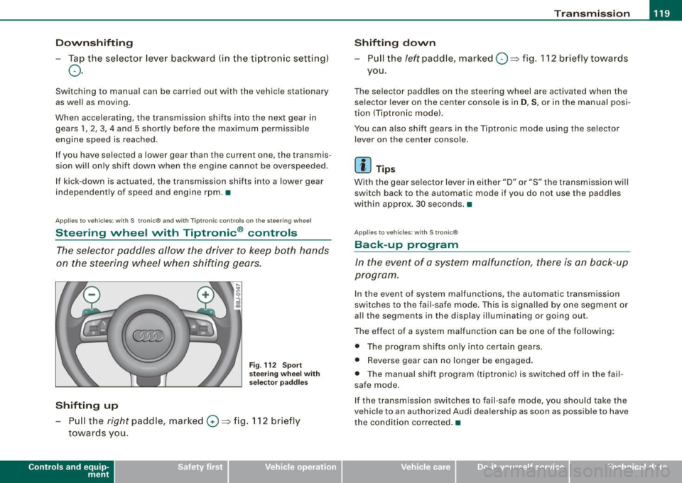
The selector paddles allow the driver to keep both hands
on the steering wheel when shifting gears.
Shifting up
F ig . 112 S port
stee ring w he el wi th
se lector paddl es
- Pu ll the right paddle, marked 0 => fig . 112 briefly
towards you .
Contro ls and eq uip
ment
Shifting d own
Pull the left paddle, marked O ::::> fig. 112 brief ly towards
you .
The selector paddles on the steering wheel are activated when the
selector lever on the center console is in
D, S, or in the manual posi
tion (Tiptronic model.
You can also shift gears in the Tiptronic mode using the selector
lever on the center console .
[ i ] Tips
With the gear se lector lever in either "D" or "S" the transmission wi ll
switch back to the automatic mode if you do not use the paddles
within approx . 30 seconds .•
App lies to vehic les: w ith S tronic®
Back -up program
In the event of a sys tem malfunction, there is an back-up
program .
In the event of system malfunctions, the automatic transmission
switches to the fai l-safe mode . This is signa lled by one segment or
al l the segments in the display illuminating or going out.
The effect of a system ma lfunction can be one of the fo llowing :
• The program shifts only into certain gears.
• Reverse gear can no longer be engaged .
• The manua l shift program (tiptronicl is switched off in the fail
safe mode.
If the transmission switches to fail-safe mode, you should take the
vehicle to an authorized Audi dea lership as soon as possible to have
the condition corrected .•
Vehicle care I I irechnical data