AUDI TT ROADSTER 2011 Workshop Manual
Manufacturer: AUDI, Model Year: 2011, Model line: TT ROADSTER, Model: AUDI TT ROADSTER 2011Pages: 260, PDF Size: 64.11 MB
Page 51 of 260
Convenience opening
• Press the unlock button @ on the remote
control key to unlock the vehicle.
• Turn the key in the driver door
once to posi
tion @
c::> fig. 48.
• Within two seconds turn the key a second
time and hold it in th is position until the
power top has completely retracted .
Convenience closing
• Turn the key in the driver door once to posi
tion @
c::> fig. 48.
• Within two seconds tu rn the key a second
time and hold it in th is position until the
power top has completely closed .
Opening or closing motion stops
immediately
as soon as you re lease the key. For safety rea
sons, it is no t possible to activa te the conven
ience feature with the remote control.
.,&. WARNING
When open ing and closing the power top
make sure to keep yourself a nd others
clear of al l moving parts. Risk of injur y!
Wind Deflector
The wind deflector reduces turbulence in the
passenger compartment and makes driving
more comfortable.
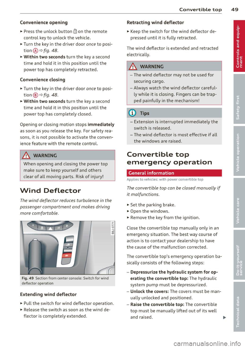
F ig. 49 Sect io n fr om center co nsole : Sw itch for w ind
def lec tor ope ra ti on
Extending wind deflector
• Pull the switch fo r wind deflector operation.
• Re lease the switch as soon as the wind de
flector is completely extended.
Convertible top 49
Retracting wind deflector
• Keep the switch for the wind deflector de
pressed until it is fully retracted.
T he w ind deflecto r is extended and retracted
electri cal ly.
.,&. WARNING
--
- The wind def lector may not be used for
securing cargo .
- Always watch the wind deflector careful
ly whi le it is closing. Fingers can be trap
ped painfully in the mechanism!
(0 Tips
-Extension is interrupted immed iate ly the
switch is released.
- Th e wind deflecto r is most effect ive if all
the windows are raised.
Convertible top
emergency operation
, General information
Applies to vehicles: with power convertible top
The convertible top can be closed manually if
it malfunctions .
.,. Set the parking brake.
.,. Open the w indows .
.,. Remove the key from the ignition.
Close the convertible top manually only in an
emergency situation. The best way course of
action is to contact your dealersh ip to have
the cause of the malfunct ion corrected .
The convertible top's emergency operation ba
sically consists of the following steps:
- Depressurize the hydraulic system for op
erating the convertible top :
The hydraulic
system pump must be depressuri zed.
- Unlock the covers: The covers must be man
ually unlocked and positioned.
-Raise the convertible top: The convertible
top must be manually lifted out of its well
and ra ised. .,.
Page 52 of 260
50 Convertible top
-Lock the conve rtible top: The latches for
the convertible top must be locked with the
emergency lock key.
-Close the hydraulic system's emergency
operation bolt:
Turn the emergency opera
tion bolt
c:> page 50, fig. 50 to the r ight to
close the hydraulic system that operates the
convertible top .
A WARNING
-When ra ising the convert ible top, take
care not to reach into the linkage that
operates the convert ible top or any of its
other moving parts. Otherwise, your
h ands may be trapped in the mecha nism
- risk of injury!
- Never drive while the convertible top is
not properly secu red. Otherwise, it may
be pulled open by the wind. This can
cause injuries and damage to the vehicle
- danger of an accident!
(D Tips
Get a second person help you to close the
convert ible top . It is much easier to raise
the co nvertib le top with the help of a sec
ond person.
Step 1: Depressurizing the hydraulic
system
Applies to vehicles: with power convertible top
-
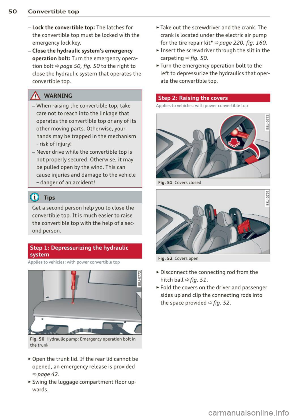
Fig. SO Hydraulic pu mp: Emerge ncy operation bo lt in
the trun k
.,. Open the trunk lid. If the rear lid cannot be
opened, an emergency release is provided
c:>page42 .
.,. Swing the luggage compartment floor up
wards.
-
.,. Take out the screwdriver and the crank . The
crank is located under the electric air pump
for the t ire repair kit*
c:> page 220, fig. 160 .
.,. Insert the screwdriver through the slit in the
carpet ing
c:> fig. 50.
.,. Turn the emergency operation bolt to the
left to depressurize the hydraulics that oper
at e the convertible top.
Step 2 : Raising the covers
Applies to vehicles: with power convertible top
Fig. 51 Covers closed
Fig. 52 Covers ope n
.,. Disconnect the connect ing rod from the
hitch ball
c:>fig. 51 .
.,. Fold the covers on the driver and passenger
sides up and cl ip the connect ing rods into
the space provided
c:> fig. 52 .
Page 53 of 260
Step 3: Closing the convertible top
Applies to vehicles: with power convertible top
The convertible top must be raised by hand.
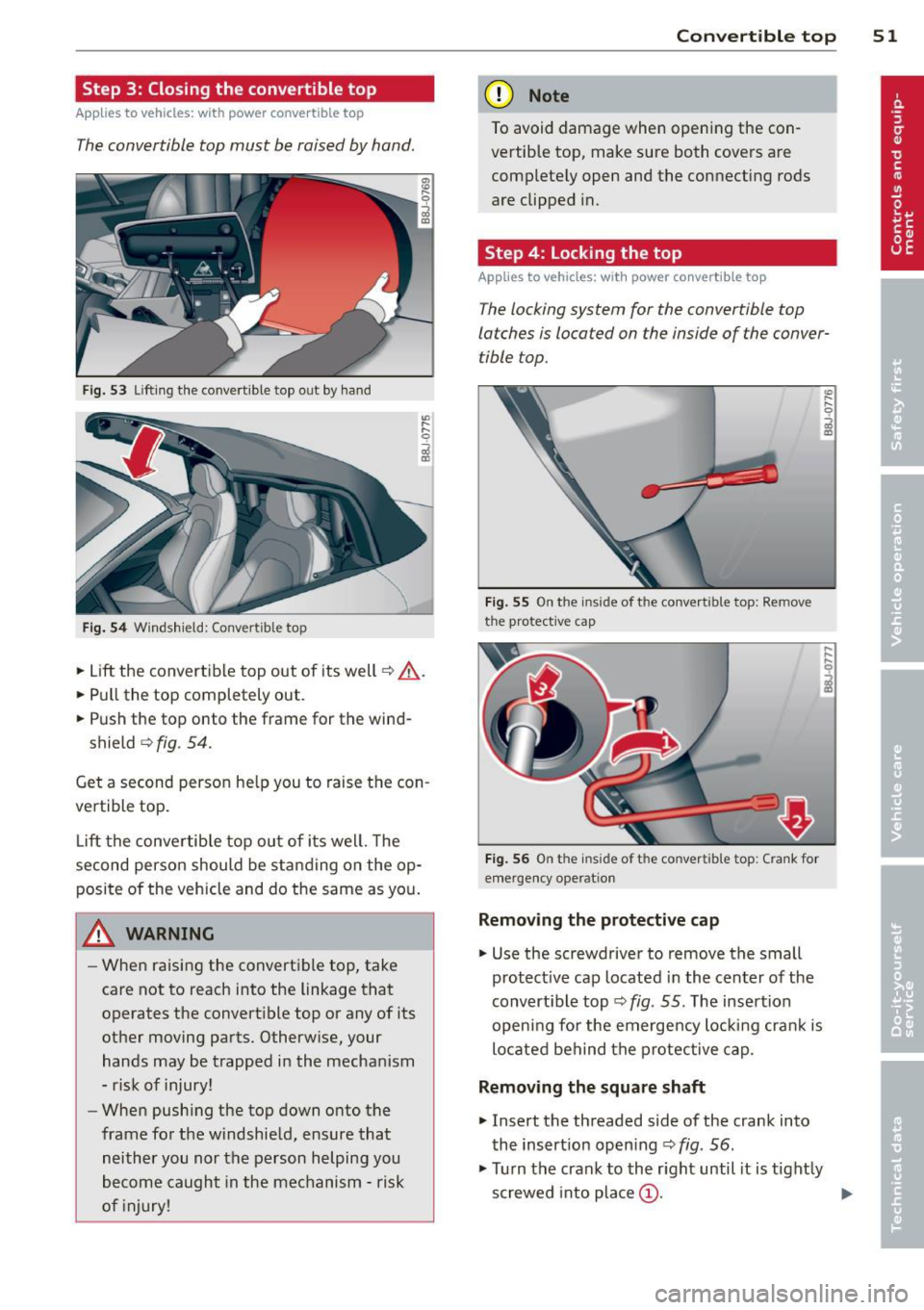
Fig. 53 Lifting the convert ible top out by hand
Fig . 54 Windshield: Convert ible top
~ Lift the convertible top out of its well~.&_.
~ Pull the top completely out.
~ Push the top onto the frame for the wind-
shield
~ fig . 54.
Get a second person he lp you to raise the con
vertible top.
Lift the convertible top out of its well. The
second person should be standing on the op posite of the vehicle and do the same as you.
A WARNING
- When raising the convertible top, take
care not to reach into the linkage that
operates the convert ible top or any of its
other moving parts. Otherw ise, your
hands may be trapped in the mechanism
- risk of injury!
- When push ing the top down onto the
frame for the windshield, ensure that neither you nor the person helping you
become caught in the mechanism - risk
of injury!
-
Con vert ible top 5 1
(D Note
To avoid damage when opening the con
vertible top, make sure both covers are
completely open and the connecting rods
are clipped in.
Step 4: Locking the top
Applies to vehicles: wit h power convertible top
The locking system for the convertible top
latches is located on the inside of the conver
tible top.
Fig. 55 On the inside of the conve rtible top: Remove
the protective cap
Fig. 56 On the inside of the convert ible top: Crank for
emergency operat ion
Removing the p rotecti ve ca p
~ Use the screwdriver to remove the small
protect ive cap located in the center of the
convert ible top ~
fig. 55. The insertion
open ing for the emergency locking crank is
located behind the protective cap.
Removing the square shaft
~ Insert the threaded side of the crank into
the insert ion open ing ~
fig. 56.
~ Turn the crank to the right until it is tight ly
screwed into place @.
Page 54 of 260
52 Convertible top
• Pull the c rank with the square shaft thread
e d onto it downward to remove the shaft
completely @.
Using the crank to lock th e convertible
top
• Insert the other side of the crank (with the
mult ipoint head) into the opening until the
stop r ing lies aga inst the closing motor®
¢fig . 56.
• Turn the crank clockwise to open the retain
ers and pull the convert ible top down at the
s ide .
• Turn the crank cou nte r-clockw ise u nti l the
top is fully loc ked in place and t he indicator
li ght on the inst rument cl uste r goes out .
• Pull the crank out.
• Unscrew the sq uare shaft from the crank .
• Insert the square shaft into the opening un
t il you hear it click into place.
• Use the protective cap to close off the inser-
t ion open ing .
The convertible top is now completely closed .
Have the malfunct ion repaired as soon as pos
sib le.
Tips
T u rn the emergency operat ion screw in the
luggage compartment to the r ight to close
the co nvertib le top hydraulic system.
Page 55 of 260

Clear vision Lights
Switching the headlights on and off
Fig . 57 Instrument pane l: light switch
F ig. 58 Instrument pane l: light switch w ith daytime
running lights (DRL)
The light switch must not be overturned past
the stops in
either dire ct ion.
Switching on automatic headlight
control*
.,. Turn the light switch to AUTO* ¢ fig. 57 .
Switching on the side ma rker lights
.,. Turn the light switch to ,oo:.
Switching on the headlights and high
beam
.,. Turn the light switch to gD .
.,. Push the high beam lever forward towards
the instrument panel¢
page 55.
Switching off the lights
.,. Turn the light switch to 0.
The headlights only work when the ignition is
switched on. While starting the engine or
when switching
off the ignition, the head-
Clear vision 53
lights will go off and only the side marker
lights will be on.
Daytime running lights (DRL) (USA
models)
The daytime r unning lights can be turned on
or
off using this function. If the function is ac
tive, the daytime running lights are turned on
automatica lly when the ignition is switched
on.
The daytime running lights are activated
only
when the light switch is at the AUTO* or DRL *
position.
Daytime running lights (Canada models
only)
The daytime running lights are activated only
when the light switch ¢ fig. 57 is either at the
0 or the ,oo: position.
The daytime r unning lights function cannot be
turned
off .
Automatic headlight control*
In the switch position AUTO the automatic
headlight control
is turned on. The low
beams are turned on automatically through a
light sensor as soon as ambient brightness
(e .g. when driving into a tunnel) falls below a
value preset at the factory. When ambient
brightness increases aga in, the low beams are
turned
off again automatica lly c:> & .
In the AUTO position the low beams are
switc hed
off automatically when the ignition
is tur ned
off.
Light Sensor Malfunction*
In the event of a light sensor malfunction, the
driver is notified in the instrument cluster dis
play:
ral Automatic headlights/automatic wipers
defective
For safety reasons the low beams are turned
on permanen tly with the switch in
AUTO* .
However, you can continue to turn the lights
on and
off using the light switch. Have the ..,.
Page 56 of 260

54 Clear vision
light sensor checke d as soon as possi ble at a
d ea le rship.
Com ing home /le aving home function *
The function is switched on when the switch is
i n the AU TO* position and the function is
shown as active in the driver info rmation sys
tem .
The
co ming h om e function illuminates the
a rea around the veh icle when the ig nition is
switc hed off and the driver 's door is opened.
The length of time the lights remain on can be set in the menu display
( Illumin ation > Exte
r io r light s> co ming hom e).
The leaving home function i lluminates the
area around the vehicle when unlock ing it.
A WARNING
- Never use daytime running lights to see
where you are going. They are not bright
enough and w ill not let you see far
enough ahead for safety, especially at
dusk or when it is dark. Always switch on
the low beams at dusk or when it is dark.
- Automatic headlights are only intended
to assist the dr ive r. They do not relieve
the driver of his responsibility to check
the headlights and to tu rn them on man
ually according to the current light and
visibili ty cond itions. Fo r example, fog
and rain cannot be detected by the light
sensors . So a lways switch on the head
lights under these weather cond itions
and when driving in the dark
io.
- Crashes can happen when yo u cannot see
the road ahead and when you cannot be seen by other motorists .
- Always turn on the headlights so that
you can see ahead and so tha t others
can see yo ur ca r from the bac k.
- With the switch in
AUTO front fog lights
ca nnot be t urned on in addition .
- The light sensor for headlight control is
l ocated in the rear view m irror mount .
Do no t apply a ny stickers to the w ind- shield in this area to prevent malfunc
tions or fa ilures.
- Some exter io r li ght ing funct ions can be
adjusted in the driver informat ion sys
tem
~ page 21.
- If you remove the ignition from the igni
tion lock while the headlights are still
on, a buzzer wi ll sound as long as the
dr iver's door is open to rem ind you to
turn off the lights.
- Always observe the specif ic loca l regu la
tions for your area as to when to use your
lights.
- With automatic headlights, the high
beam funct ion is also available, but wit h
one restrict ion: If you have not switched
the high beams back to low beams dur
ing automatic headlight operation (fo r
example, after d rivi ng through a tunnel) ,
only the low beams come on the nex t
t ime au tomatic headlights are swi tched
on. To use the high beams, you first have
to pull the high beam lever back and
then push the lever forward again.
- In cool or damp weather, the inside of
the headlig hts, turn signals and tail
lights can fog over due to the tempera
t u re difference between the inside and
outside. They w ill clear shortly after
switching them on. This does not affect
the se rv ice life of the lig hting .
Adaptive light
Applies to veh icles: w ith Adapt ive Light
When driving around bends, the relevant area
of the road is better illuminated.
F ig . 59 Adapt ive li ght w hen dr iv in g
Page 57 of 260
The benefit o f adaptive light is that the curve
and the edg e of th e road are better i lluminat
ed
c::> fig . 59. T he adaptive light is controlled
automatically , depend ing on veh icle speed
and steering wheel ang le.
When driving a round bends, the head lights
are contro lled according to steer ing wheel an
g le. So that there is no black area ahead of the
ve hicle, the two main beams pivo t at different
angles.
(D Tips
T he system works above a speed of about
6 mph (10 km/h) .
Front fog lights
Use the light switch to turn on the front fog
lights.
0 0
"' -ci. a) a,
F ig . 6 0 Fog l ig ht activat ion : ligh t switc h pos it io n on ve ·
hides WIT HO UT s ensor lig ht
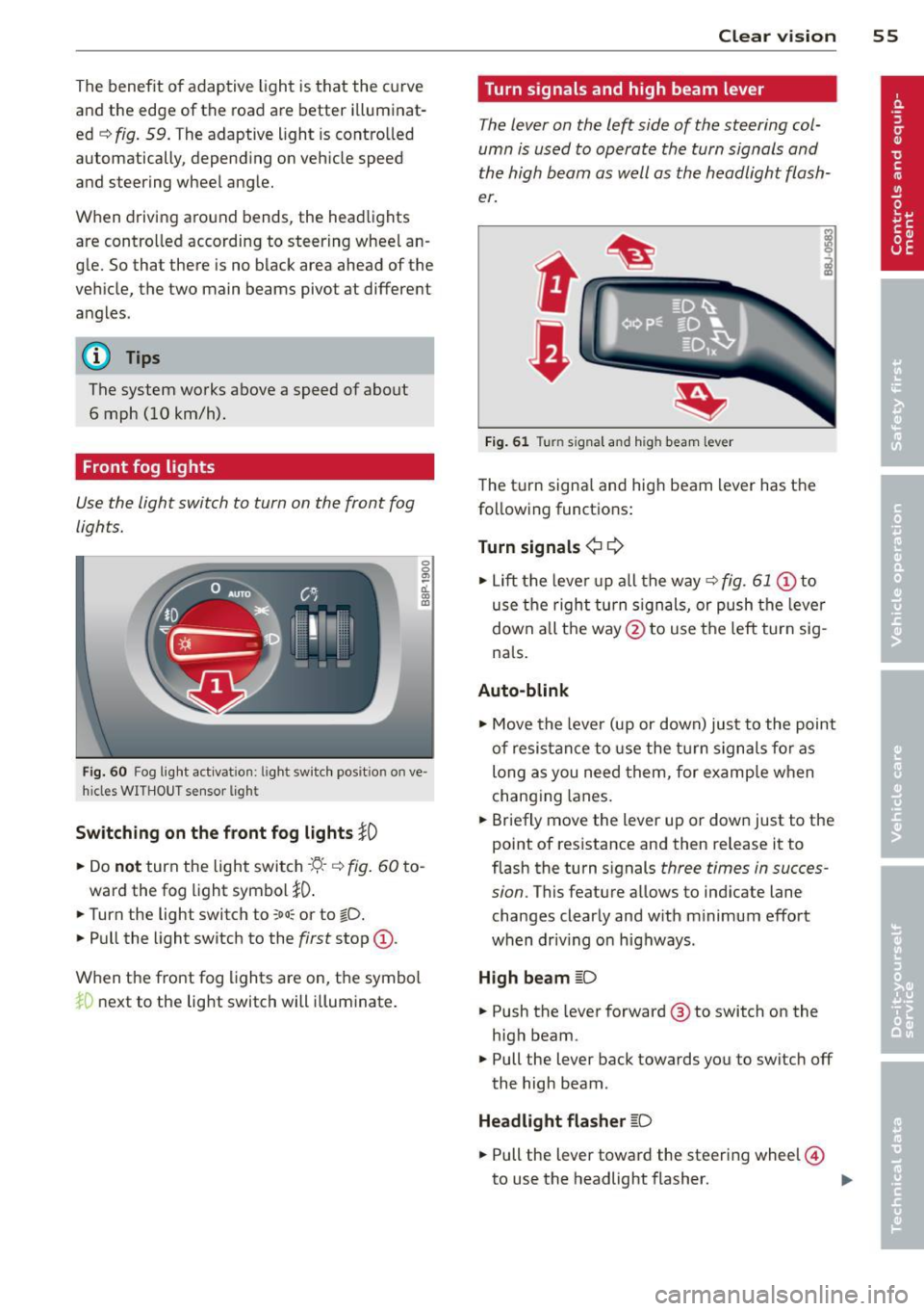
Switching on the f ront fog lights }0
• Do not turn the light swi tch -'ti--c::> fig . 60 to -
ward the fog light symbol
}D .
• Turn the light switch to ~oo; or to tD .
• Pull the light switch to the first stop @.
When t he front fog lights are on, the symbo l
iD next to the lig ht switch will illuminate .
Clear vision 55
Turn signals and high beam lever
The lever on the left side of the steering col
umn is used to operate the turn signals and
the high beam as well as the h eadlight flash
er.
t
'
Fi g. 61 Tu rn signal and high beam lever
The turn signa l and high beam lever has t he
following functions:
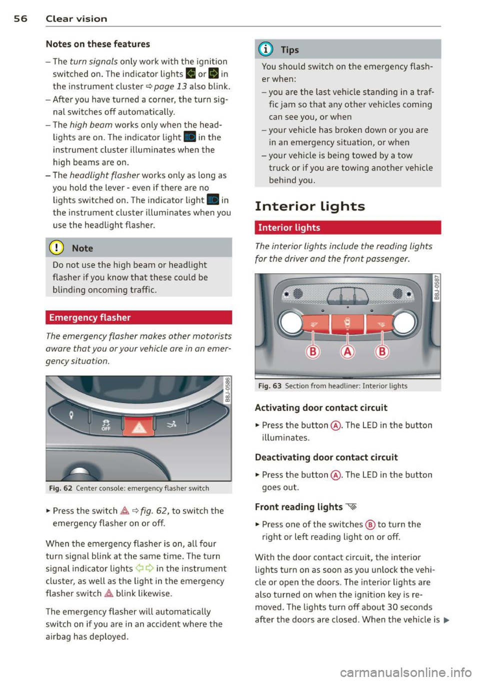
Turn signals ¢
9
• Lift the leve r up a ll the way c::> fig. 61 @ to
use t he right turn s ignals, or push the leve r
down all the way@to use t he left tur n sig
na ls .
Auto -blink
• Move the leve r (up or down) just to the point
of resistan ce to use the turn signa ls fo r as
long as you need them, for e xamp le w hen
chang ing lanes.
• Briefly move the lever up or down just to the
point of resistance and then release it to
flash the turn s ignals
three times in succes
sion .
This featu re allows to ind icate lane
changes clearly and w ith m inimum effort
when driv ing o n highways .
High beam
~D
• Push the lever forward @ to switch on the
high beam .
.. Pull the lever back towards you to switch off
the high beam .
Headlight flasher
~D
• Pull the lever toward the steering wheel@
to use the headlight flasher. ..,.
Page 58 of 260
56 Clear vis ion
Notes on the se feature s
- The turn signals only work with the ignition
swit ched on . The indicator lights
(I or IN in
the instr ument cl uster ¢
page 13 also b link .
- After you have turned a corner, the turn sig-
nal switches off a utomat ica lly.
- T he
high beam works only when the head
lights are on. The indicator light . in the
instrument cluster illuminates when the
high beams a re on.
- The
headlight flasher wo rks on ly as long as
yo u hold the lever -even if there are no
lights switched on. The indicator light . in
the instrument cl uster illum inates when you
use the headlight f lasher.
(D Note
Do not use the high beam or headlight
flasher if you know that these cou ld be
blind ing oncoming traffic.
Emergency flasher
The emergency flasher makes other motorists
aware that you or your vehicle are in an emer
gency situation.
F ig . 6 2 Cente r console: emerge ncy flas her sw itch
,. Press the switch ~ ~ fig. 62, to switch the
eme rgency flasher on or off .
When the emergency f lashe r is on, a ll four
turn sig nal bli nk at the same time. The t urn
sig nal i ndi ca tor lights ¢ Q in the ins trument
cluster, as well as the lig ht in t he emergen cy
f lasher switch ~ blink likewise .
The emergency flasher w ill automat ica lly
switch on if you are in an a cciden t where the
a irbag has deployed.
(D Tips
You should switch on t he emergency f lash
er when:
- you are the last veh icle standing in a traf
fic jam so that any other vehicles coming can see you, or when
- your vehicle has broken down or you are
in an emergency s ituation, or when
- your vehicle is being towed by a tow
truck or if you are tow ing another vehicle
beh ind you.
Interior lights
' Interior lights
The interior lights include the reading lights
for the driver and the front pass enger.
F ig . 63 Sect ion from headliner: Interio r lights
Activating door contact circuit
,. Press the b utton @. The L ED in the b utton
illum inates.
Deactivating door contact circuit
,. Press the button @. The LED in the button
goes o ut.
Front reading lights "<~
.. Press one of the switches ® to turn the
r ight or left reading light on or off.
With the door contact circuit, the interior lights turn on as soon as you unlock the vehi-
cle or open the doors. The interior lig hts are
also t urned on when the ign ition key is re
moved . The lights turn off about 30 seconds
after the doo rs ar e closed. When the ve hicle is
lilJJ,
Page 59 of 260

locked or when the ignition is turned on, the
interior lights are turned off.
When a door is open, the interior l igh ts are
turned off afte r abo ut 10 m inu tes to p reven t
battery draining.
The brightness of the lights is controlled au
t om atically by a dimmer when they are
sw itched on and off.
Instrument panel illumination
The illumination of the instruments, displays
and the cen ter console can be adjusted .
Fig . 64 Instr ument pane l illu min at io n
i a:. .. a,
You regulate the brightness of the instru
ments with the left thumbwheel
Co/¢ fig. 64 .
Ign ition ON, light switch at @.
Wit h t he igni tion swi tched ON, the glow o f in
strument needles
can be adjusted to a ppear
b righter or dimmer.
Ignition ON , light switch at ~oQ: or ~D .
With the l igh ts sw itched on, the brightness of
i nstr ument cluster (i.e. needles, gauges and
d isp lays) and center console i llumination can
be ad justed .
(D Note
The instrument cluster and cente r console
illumination (ga uges and needles) comes
on when you switch on the ignition and the
vehicle headlights are off. Be aware of t he
following difference between mode ls built
to US or Ca nadian specifications:
- USA models: illumination of the instru
ment cluster (gauge s and needles),
dash and cente r console around the
Clear vi sion 5 7
gearshift lever is controlled by a light
sensor located in the in strument panel.
The in strument panel illumination will
automatically become dimmer as the
daylight fades away and eventuall y will
go out completely when outside light is
very low . This i s to remind you, the driv
er, to switch on the headlights before it
get s too dark.
- Canada models: in strument pan el illu
min ation w ill stay bright r egardless of
the intensit y of ambient light . Alwa ys
be aware of changes in out side light
conditions while you are dri ving. Re·
s pond in time to fading daylight by
turning the light switch to position
~D
(or "AUTO" if your car is equipped with
this feature)
to turn on you r headlights.
luggage compartment light
The light is located on the right side of the
luggage compartment.
These lights come on automatically when t he
rear lid is opened . The lights turn off automat
ical ly if the lid is left open for more then 10
minutes .
Vision
Sun visors
Using the sun visors make s driving safer .
Fig. 65 Sun visor
- ~ ---------.ttr -···---=-=---------~=--·-·----- -·-==:. - · =-~-----
The vanity mirrors in the sun visors are equip
ped with lids. Push lid in direct ion of arrow to
open.
Page 60 of 260

58 Clear vis ion
Mirrors
Manual glare dimming
Standard sett ing
.,. Move the small lever (located on the bottom
edge of the mirror) to the front .
Anti-glare setting
.,. Move the small lever (located on the bottom
edge of the mirror) to the rear.
Automatically dimming inside mirror
App lies to vehicles: with automat ically dimming inside
rearview mirror
The automatic dimming function con be
turned on and off if required.
Fig. 66 Inside rea rvi ew mir ror, d ig ita l compass ac tivat
ed: a uto dimmin g on/off b utt o n an d indicator ligh t
Disabling auto dimming
.,. Press button @briefly, -the gree n indicator
l ight @ goes out .
Activating /reactivating auto dimming
.,. Press button @briefly, -the green indicator
light @goes on.
Automatic dimming function
The a utomatic dimming function is activated
every time the ignition is turned on. The green indicator light is lit to indicate auto dimming
is active .
When dimming is activated, the inside mirror
will darken
automa tically in response to the
amount of light str ik ing the m irror (such as
headlights from rearwa rd approaching veh i
cles) . Even in dimming mode, the mirror su r
face turns bright when: -
the interior lig ht is switched on
- reve rse ge ar is engaged.
Sensors for automatic headlights*
With the he lp of the se nsors i n the mir ror,
whe n the light switch is in the
AUTO posit ion,
t h e low beams a re sw itc hed on an d off auto
matically de pending on the ambient light co n
di tions
q page 53 .
.&_ WARNING
Broken g lass o f aut oma tic dimm ing mir ror
ca n cause electrolyte f luid lea kage . Elec
trolyte f luid can irritate skin, eyes , and res
pirato ry system.
- Repeated or prolonged ex posu re to e lec
trolyte can cause irritation to the respira
tory system , especially among people
wit h asthma or other resp iratory condi
tions . Get fresh air immediately by leav
i n g the veh icle o r, if that is no t possib le,
op en w indows and doo rs all the way.
- If electroly te gets into the eyes, flus h
them thorough ly with large amounts of
clean water fo r at least 15 minu tes;
m edical attenti on is recom mend ed.
- I f electrolyte contac ts skin, fl ush affect
e d area w ith clean wate r fo r at lea st 15
minu tes and t hen wa sh affected area
wit h soap an d wate r; medical atte ntion
is recommended . Thoro ughly wash af
fected clothi ng and shoes before re use .
-If swallowed and person is conscious,
rinse mout h with water for at least 15
m inutes . Do not induce vomiting unless
instr ucted to do so by medica l professio
na l. Get medical attention immediately.
(D Note
Liq uid electrolyte leaked from a broke n
mir ro r glass w ill damage any plastic s urfa
ces it comes in contact with. Clean up sp il
l ed e lectrolyte immed iate ly w ith clear wa
ter and a sponge .
(!} Tips
-If you switch off the automatic dim
ming funct ion on the inside mirror ,