rear BMW 525i 1997 E39 Workshop Manual
[x] Cancel search | Manufacturer: BMW, Model Year: 1997, Model line: 525i, Model: BMW 525i 1997 E39Pages: 1002
Page 634 of 1002
Downloaded from www.Manualslib.com manuals search engine
300-1 4
I Susoension. Steerina and Brakes - General
DSC system I
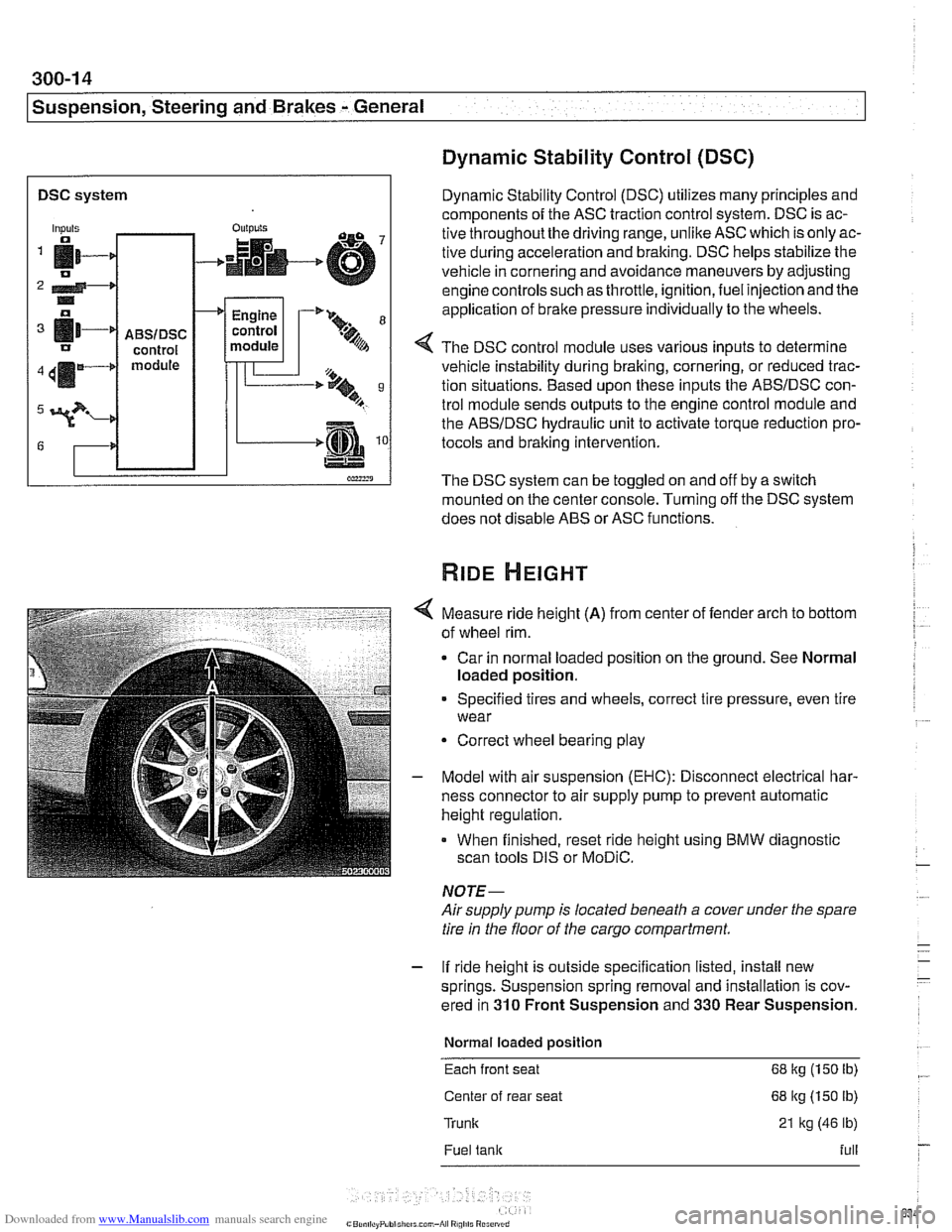
Dynamic Stability Control (DSC)
Dynamic Stability Control (DSC) utilizes many principles and
components of the ASC traction control system. DSC is ac-
tive throughoutthe driving range, unlike ASC which is only ac-
tive during acceleration and braking. DSC helps stabilize the
vehicle in cornering and avoidance maneuvers by adjusting
engine controls such as throttle, ignition, fuel injection and the
application of
brake pressure individually to the wheels.
Inputs
fi- 0
2 4-* .. o
[11-' IJ
411m4
3?-
G
4 The DSC control module uses various inputs to determine
vehicle instability during braking, cornering, or reduced trac-
tion situations. Based upon these inputs the ABSIDSC con-
trol module sends outputs to the engine control module and
the ABSIDSC hydraulic unit to activate torque reduction pro-
tocols and braking intervention.
-
ABSIDSC control module
OUI~YIS
4
The DSC system can be toggled on and off by a switch
mounted on the center console. Turning off the DSC system
does not disable ABS or ASC functions.
+
Measure ride height (A) from center of fender arch to bottom
of wheel rim.
Car in normal loaded position on the ground. See Normal
loaded position.
Engine
control
module
Specified tires and wheels, correct tire pressure, even tire
wear
-'* 9-
.%A
Correct wheel bearing play
T'== ..t, 9 B
-.m
Model with air suspension (EHC): Disconnect electrical har-
ness connector to air supply pump to prevent automatic
height regulation.
When finished, reset ride height using BMW diagnostic
scan tools DIS or
MoDiC.
NOTE-
Airsupply pump is located beneath a cover under the spare
tire in the floor of the cargo compartment.
- If ride height is outside specification listed, install new
springs. Suspension spring removal and installation is cov-
ered in
310 Front Suspension and 330 Rear Suspension.
Normal loaded position
Each front seat 68 kg (150 Ib)
Center of rear seat 68 kg (150 lb)
Trunk 21 kg (46 lb)
Fuel tank full
Page 636 of 1002
Downloaded from www.Manualslib.com manuals search engine
300-1 6
I Suspension, Steering and Brakes - General
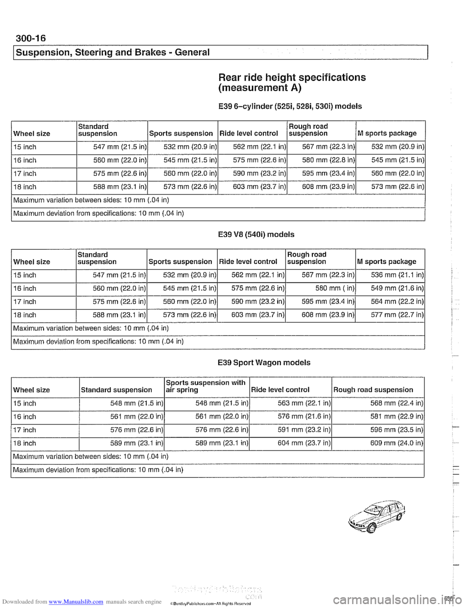
Rear
ride height specifications
(measurement
A)
E39 6-cylinder (5251,5281,530i) models
E39 VB (540i) models
Wheel size
15 inch
16 inch
17 inch
18 inch
Maximum variation between sides: 10
mm (.04 in)
Maximum deviation from specifications: 10
mm (.04 in)
Standard
suspension
547 mm (21.5 in)
560
mm (22.0 in)
575 mm (22.6 in)
588 mm (23.1 in)
I I I I I
Maximum variation between sides: 10 mm (.04 in)
Wheel
size
15 inch
16 inch
575 mm (22.6 in)
Maximum deviation from specifications: 10 mm
(.04 in)
Sports suspension
532 mm (20.9 in)
545 mm (21.5 in)
560 mm (22.0 in)
573
mm (22.6 in)
Rough road
suspension
567
mm (22.3 in)
580 mm
( in)
E39 Sport Wagon models
M sports package
536
mm (21.1 in)
549 mm (21.6 in)
Standard
suspension
547 mm (21.5 in)
560 mm (22.0 in)
588 mm (23.1
in)l 573 mm (22.6 in)/ 603 mm (23.7 in)l 608 mm (23.9 in)l 577 mm (22.7 in)
560
mm (22.0
in) Ride level
control
562
mm (22.1 in)
575 mm (22.6 in)
590 mm (23.2 in)
603 mm (23.7 in)
Sports suspension 532
mm (20.9 in)
545 mm (21.5 in)
590
mm (23.2 in) Rough
road
suspension
567
mm (22.3 in)
580 mm (22.8 in)
595 mm (23.4 in)
608 mm (23.9 in)
Ride level control
562
mm (22.1 in)
575 mm (22.6 in)
Wheel size
15 inch
M sports package
532
mm (20.9 in)
545
mm (21.5 in)
560 mm (22.0 in)
573 mm (22.6 in)
595
mm (23.4 in)
Sports suspension with
air spring
548 mm (21.5 in)
Standard
suspension
548
mm (21.5 in)
16 inch
17 inch
18 inch 564
mm (22.2
in)
Maximum variation between sides: 10 mm
(.04 in)
Maximum deviation from specifications: 10 mm
(.04 in) 561
mm (22.0 in)
576
mm (22.6 in)
589
mrn (23.1 in)
561
mm (22.0 in)
576 mm (22.6 in)
589 mm (23.1 in) Ride level
control
563
mm (22.1 in) Rough road suspension
568 mm (22.4 in)
576 mm (21.6 in)
591 mm (23.2 in)
604 mm (23.7 in) 581
mm (22.9
in)
596
mm (23.5 in)
609 mm (24.0 in)
Page 648 of 1002
Downloaded from www.Manualslib.com manuals search engine
/~ront Susaension
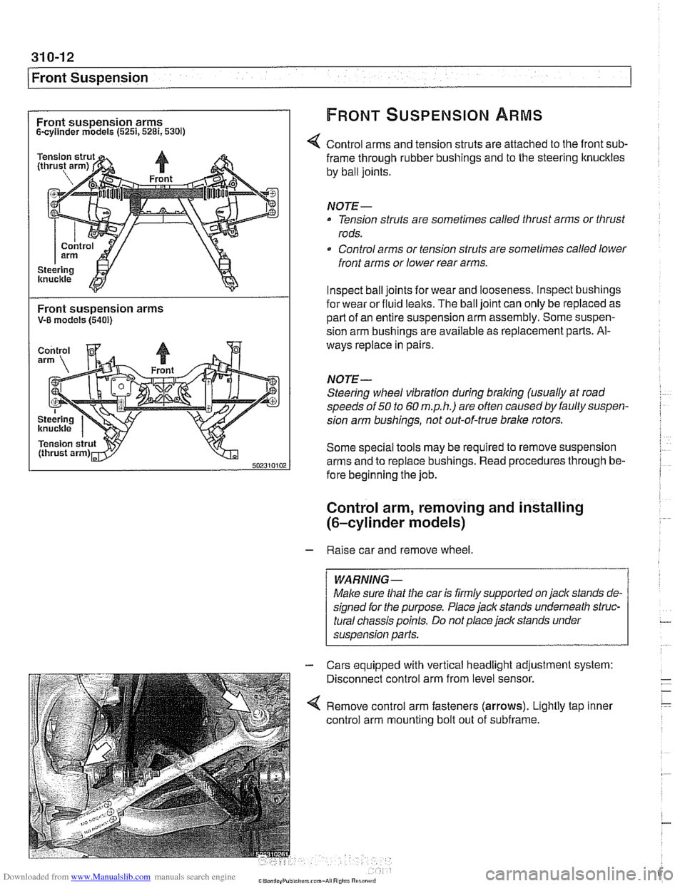
Front suspension arms FRONT SUSPENSION ARMS
Scyllnder models (5251,5281,530i)
Control arms and tension struts are attached to the front sub-
Front suspension arms V-8 models (5401)
frame through rubber bushings and to the steering ltnuckles
by ball joints.
NOTE-
Tension struts are sometimes called thrust arms or thrust
rods.
Control arms or tension struts are sometimes called lower
front arms or lower rear arms.
Inspect ball joints for wear and looseness. lnspect bushings
for wear or fluid
lealts. The ball joint can only be replaced as
part of an entire suspension arm assembly. Some suspen-
sion arm
bushinas are available as re~lacement Darts. Al-
ways replace in pairs
NOTE-
Steering wheel vibration during braking (usually at road
speeds of
50 to 60 m.p.h.) are often causedby faulty suspen-
sion arm bushings, not out-of-true brake rotors.
Some special tools may be required to remove suspension
arms and to replace bushings. Read procedures through be-
fore beginning the job.
Control arm, removing and installing
(6-cylinder models)
- Raise car and remove wheel
Male sure
that the car is firmly supported on jack stands de-
signed for the purpose. Place jack stands underneath struc-
tural chassis points. Do not place jack stands under
suspension
parfs.
Cars equipped with vertical headlight adjustment system:
Disconnect control arm from level sensor.
Remove control arm fasteners (arrows). Lightly tap inner
control arm mounting bolt out of subframe.
Page 659 of 1002
Downloaded from www.Manualslib.com manuals search engine
1 320 Steering and Wheel Alignment
General ........................... .32 0.2
Special tools
........................ .32 0.2
Steering system
..................... .32 0.4
Steering system variations
............. .32 0.5
Steering system warnings and cautions
... .32 0.6
Steering Wheel .................... .32 0.7
Steering wheel. removal and installation
.. .32 0.7
Steering Column ................. .32 0.1 0
Steering column components .......... .32 0.10
Steering column trim, removing
and replacing
...................... .32 0.10
lgnition switch ring antenna (EWS).
removing and installing
............... .32 0.1 1
lgnition lock cylinder.
removing and installing
............... .32 0-1 1
Steering column lock. removing
and installing
....................... .32 0.12
lgnition
interloclc cable. removing and installing
(models with automatic transmission)
... .32 0.13
Interlock cable. adjusting
(models with automatic transmission)
... .32 0.14
Steering column. removing and installing
. .32 0.14
Steering column adjustment motors.
removing and installing
............... .32 0.16
Power Steering Pump ............. .32 0.17
Power steering pump. removing
and installing
....................... .32 0.1 7
Power steering system.
bleeding and filling
.................. .32 0.18
Rack and Pinion Steering
(6-cylinder models)
............... 320-19
Rack and pinion steering components
(6-cylinder models)
.................. 320-1 9
Steering rack. removing and installing
.... 320-19
Steering
rack boot. replacing ........... 320-22
Tie rod (outer). replacing
.............. 320-22
Tie rod (inner). replacing
.............. 320-23
Steering Gearbox (V-8 models) .... 320-24
Steering gearbox system components
. .
(V-8 models) ....................... 320-24
Steering gearbox, removing and installing 320-25
Pitman arm. removing and installing ..... 320-28
Pitman arm. adjusting ................ 320-29
Steering idler arm. removing
and installing
....................... 320-30
Idler arm bushing. replacing ........... 320-31
Center tie rod. replacing
.............. 320-32
Wheel Alignment .................. 320-33
Camber
........................... 320-33
Caster
............................ 320-33
Front toe and toe difference angle
....... 320-34
Reartoe ........................... 320-34
Preparing for alignment
............... 320-35
Alignment specifications tables
......... 320-35
Page 666 of 1002
Downloaded from www.Manualslib.com manuals search engine
320-8
Steering and Wheel Alignment
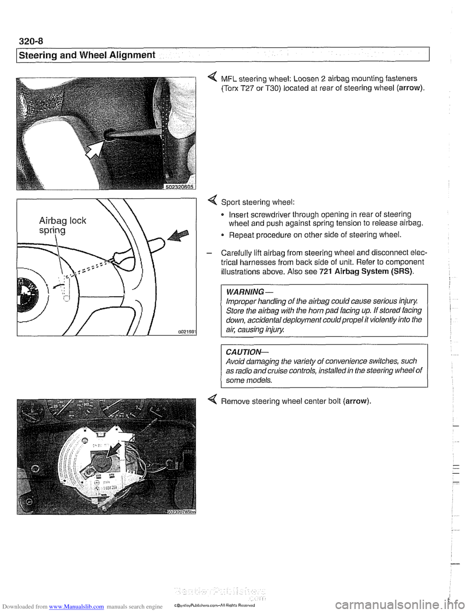
4 MFL steering wheel: Loosen 2 airbag mounting fasteners
(Torx T27 or T30) located at rear of steering wheel (arrow).
4 Sport steering wheel:
Insert screwdriver through opening in rear of steering
wheel and push against spring tension to release
airbag.
Repeat procedure on other side of steering wheel.
- Carefully lift airbag from steering wheel and disconnect elec-
trical harnesses from
back side of unit. Refer to component
illustrations above. Also see
721 Airbag System (SRS).
Improper handling of the airbag could cause serious injury.
Store the
airbag with the horn pad facing up. If stored facing
down, accidental deployment couldpropel it violently into the
Avoid damaging the variety of convenience switches, such
as radio and cruise controls, installed in the steering wheel of
4 Remove steering wheel center bolt (arrow).
Page 675 of 1002
Downloaded from www.Manualslib.com manuals search engine
Steering and Wheel Alignment
Power assist is provided by a belt-driven pump at the lower
left front of the engine. The power steering fluid reservoir is lo-
cated at the left side of the engine compartment.
Power steering pump, removing and
installing
When working with power steering components, absolute
cleanliness is needed to ensure proper operation of the hy-
- Empty power steering fluid reservoir using clean syringe. Do
not reuse fluid.
- Raise front of car. Remove splash shield from under engine.
WARNING-
Make sure the car is firmly supported on jack stands de-
signed for the purpose. Place jack stands beneath structural
chassis points. Do not place jack stands under suspension
Darts.
Remove drive belt from power steering pump. See
020 Main-
tenance.
Remove alternator cooling duct
Remove fluid hoses from pump. Plug openings in pump and
hose ends.
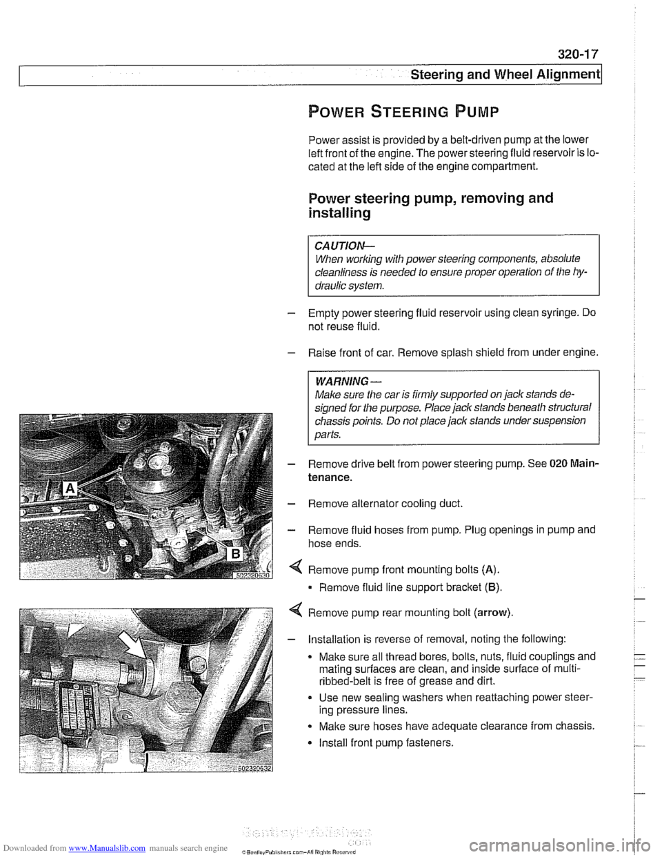
Remove pump front mounting bolts
(A).
Remove fluid line support bracket (B)
Remove pump rear mounting bolt (arrow)
- Installation is reverse of removal, noting the following:
Make sure all thread bores, bolts, nuts, fluid couplings and
mating
surfaces are clean, and inside surface of multi-
ribbed-belt is free of grease and dirt.
Use new sealing washers when reattaching power steer-
ing pressure lines.
Make sure hoses have adequate clearance from chassis.
Install front pump fasteners.
Page 676 of 1002
Downloaded from www.Manualslib.com manuals search engine
-
-steering and wheel -. Alignment I
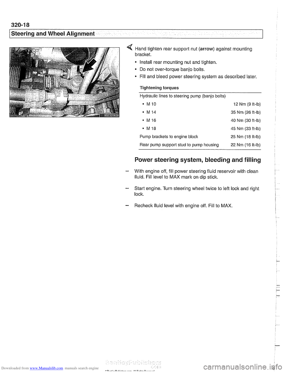
< Hand tighten rear suppoll nut (arrow) against mounting
bracket.
Install rear mounting nut and tighten.
Do not over-torque banjo bolts.
* Fill and bleed power steering system as described later.
Tightening torques
Hydraulic lines to steering pump (banjo bolts)
a MlO 12 Nm (9 ft-lb)
. M14 35 Nm (26 ft-lb)
MI6 40 Nm (30 ft-lb)
. MI8 45 Nm (33 ft-lb)
Pump
brackets to engine block 25 Nm (18 ft-lb)
Rear pump support stud to pump housing
22 Nm (16 ft-lb)
Power steering system, bleeding and filling
- With engine off, fill power steering fluid reservoir with clean
fluid. Fill level to MAX
mark on dip stick.
- Start engine. Turn steering wheel twice to left lock and right I
lock.
- Recheck fluid level with engine off. Fill to MAX.
Page 691 of 1002
Downloaded from www.Manualslib.com manuals search engine
Steerina and Wheel ~lianmentl
Proper handling, stability and driving ease depend upon the
correct alignment of all four wheels. The front axle is aligned
in relation to the rear axle, then the front wheels are aligned in
relation to one another. This is known as a four-wheel or
thrust-axis alignment.
Front and rear alignment specification are given in tables at
the end of this repair group.
BMW E39 cars use a sophisticated multi-link suspension at
the front and rear of the car. Proper alignment requires com-
puterized alignment equipment.
Camber
Front wheel camber is set at the factory and cannot be adjust-
ed. Rear wheel camber is fully adjustable.
Always set rear camber before adjusting toe
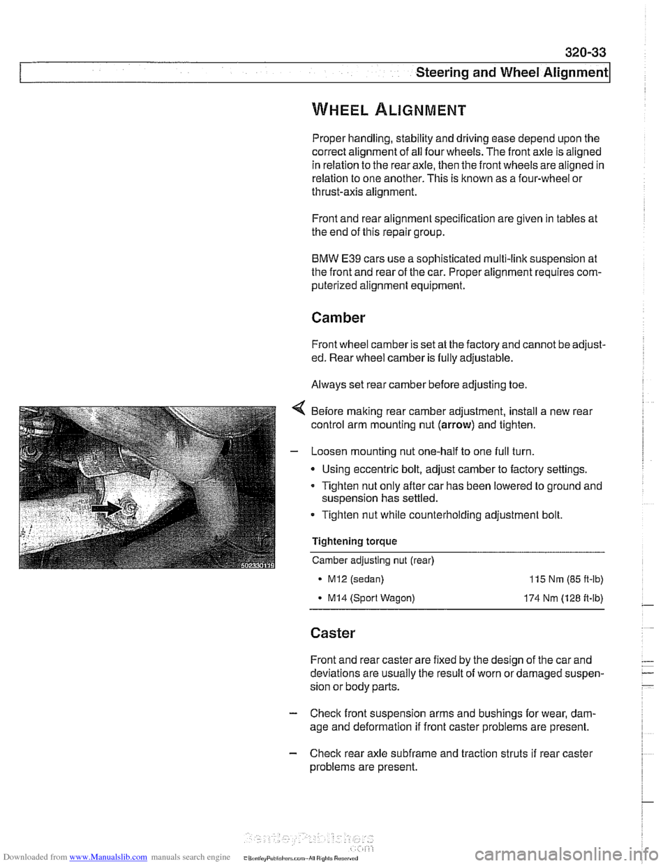
Before making rear camber adjustment, install a new rear
control arm mounting nut
(arrow) and tighten.
- Loosen mounting nut one-half to one full turn.
Using eccentric bolt, adjust camber to factory settings.
Tighten nut only after car has been lowered to ground and
suspension has settled.
Tighten nut while counterholding adjustment bolt.
Tightening torque
Camber adjusting nut (rear)
MI2 (sedan)
- MI4 (Sport Wagon)
115 Nm (85 ft-lb)
174 Nm (128 ft-lb)
Caster
Front and rear caster are fixed by the design of the car and
deviations are usually the result of worn or damaged suspen-
sion or body parts.
- Check front suspension arms and bushings for wear, dam-
age and deformation if front caster problems are present.
- Check rear axle subfrarne and traction struts if rear caster
problems are present.
Page 692 of 1002
Downloaded from www.Manualslib.com manuals search engine
320-34
I Steerins and Wheel Alignment
Front toe and toe difference angle
Toe is the difference in the distance between the front of the
front wheels and the rear of the front wheels. It is adjusted by
altering the length of the tie rods.
Toe difference angle determines the progressively different
paths taken by the front wheels as the car is turning. In
V-8
models, it is set by the pitman arm adjustment, but depends
on accurate setting of the toe.
Toe adjustments should only be made on specialized align-
ment equipment and only with the car in normal loaded posi-
tion, described below.
- Set front wheel toe at tie rod ends:
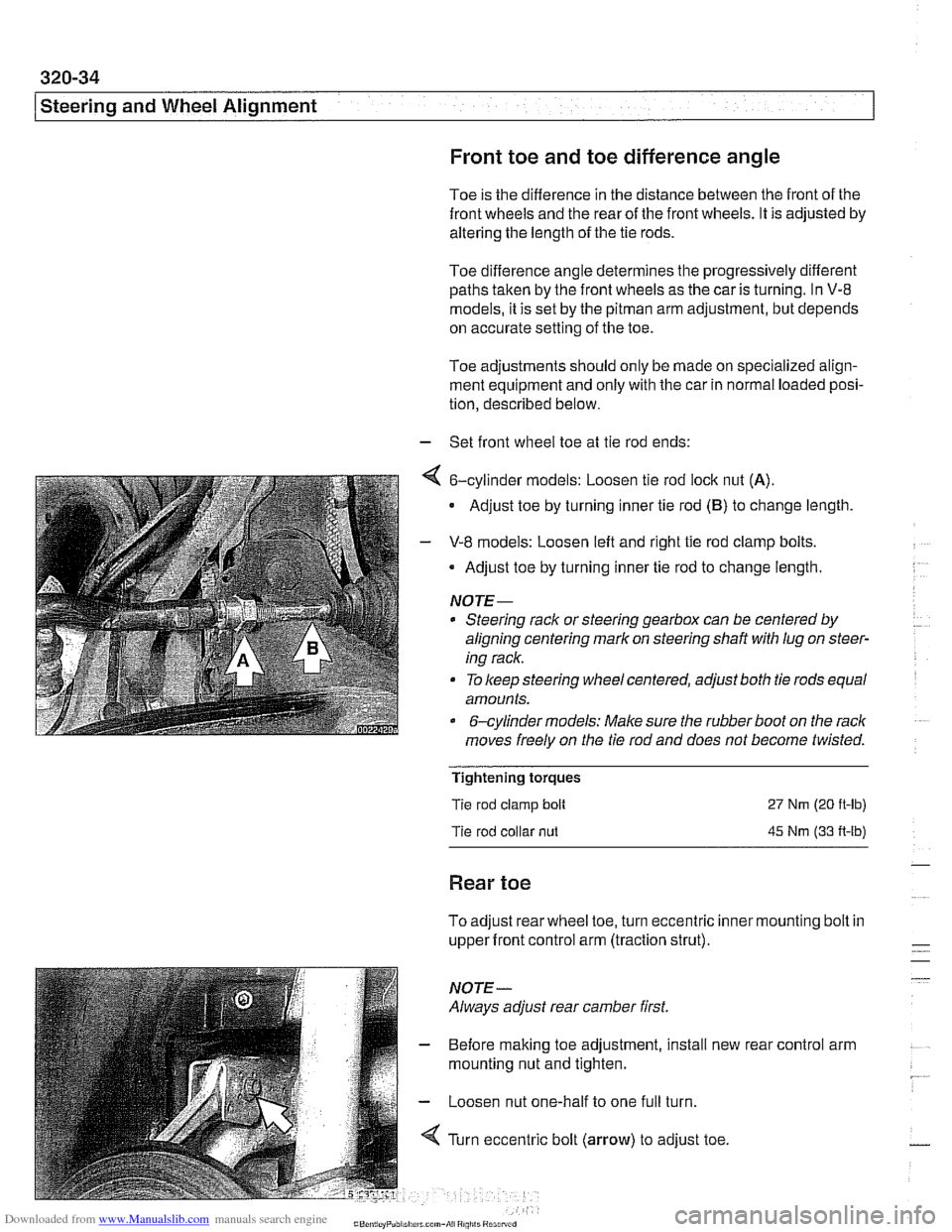
4 6-cylinder models: Loosen tie rod lock nut (A).
Adjust toe by turning inner tie rod (B) to change length
- V-8 models: Loosen left and right tie rod clamp bolts.
Adjust toe by turning inner tie rod to change length.
NOTE-
* Steering rack or steering gearbox can be centered by
aligning centering mark on steering shaft
with lug on steer-
ing rack.
To keep steering wheel centered, adjust both tie rods equal
amounts.
&cylinder models: Make sure the rubber boot on the rack
moves freely on the tie rod and does not become twisted.
Tightening torques
Tie rod clamp bolt
Tie rod collar
nut
27 Nm (20 ft-lb)
45 Nm (33 A-lb)
Rear toe
To adjust rear wheel toe, turn eccentric inner mounting bolt in
upper front control arm (traction strut).
NOTE-
Always adjust rear camber first.
- Before making toe adjustment, install new
mounting nut and tighten.
- Loosen nut one-half to one full turn.
4 Turn eccentric bolt (arrow) to adjust toe. rear
control arm
Page 693 of 1002
Downloaded from www.Manualslib.com manuals search engine
Steering and Wheel Alignment
- Tighten nut while counterholding adjusting bolt,
- Tighten nut only after car has been lowered to ground and
suspension has settled.
Preparing for alignment
- The following conditions are necessary prior to wheel align-
ment:
Correct wheels and tires are installed, in good condition,
and are at the correct inflation pressures.
All steering and suspension parts and bushings are un-
damaged and show no signs of abnormal wear. Wheel
bearings are in good condition.
Ride height is in accordance with specifications. See
300
Suspension, Steering and Brakes-General.
Car is in normal loaded position. See below.
* Cars with air suspension: Remove air suspension power
fuse.
Normal loaded position
Each front seat
68 Kg (I50 lb)
Center of rear seat
Trunlc
Fuel tank
68 Kg (150 lb)
21 Kg (46 lb)
Full
Alignment specifications tables
In the alignment specification tables that follow, reference is
made to the various types of suspension used in
E39 cars.
The type of suspension can be identified by loolting at the la-
bel on the front strut tube.
Identifying symbol
None
Solid circle
Solid triangle
M5
Circle
Triangle Version
Standard suspension
Sports
suspension
Sports suspension
M sport package
Standard suspension
Sports suspension Model
Sedan
6-cylinder sedan
V-8 sedan
V-8 sedan
Touring (Sport Wagon)
Touring (Sport Wagon)