rear BMW 525i 1997 E39 Workshop Manual
[x] Cancel search | Manufacturer: BMW, Model Year: 1997, Model line: 525i, Model: BMW 525i 1997 E39Pages: 1002
Page 694 of 1002
Downloaded from www.Manualslib.com manuals search engine
Isteering and Wheel Alignment
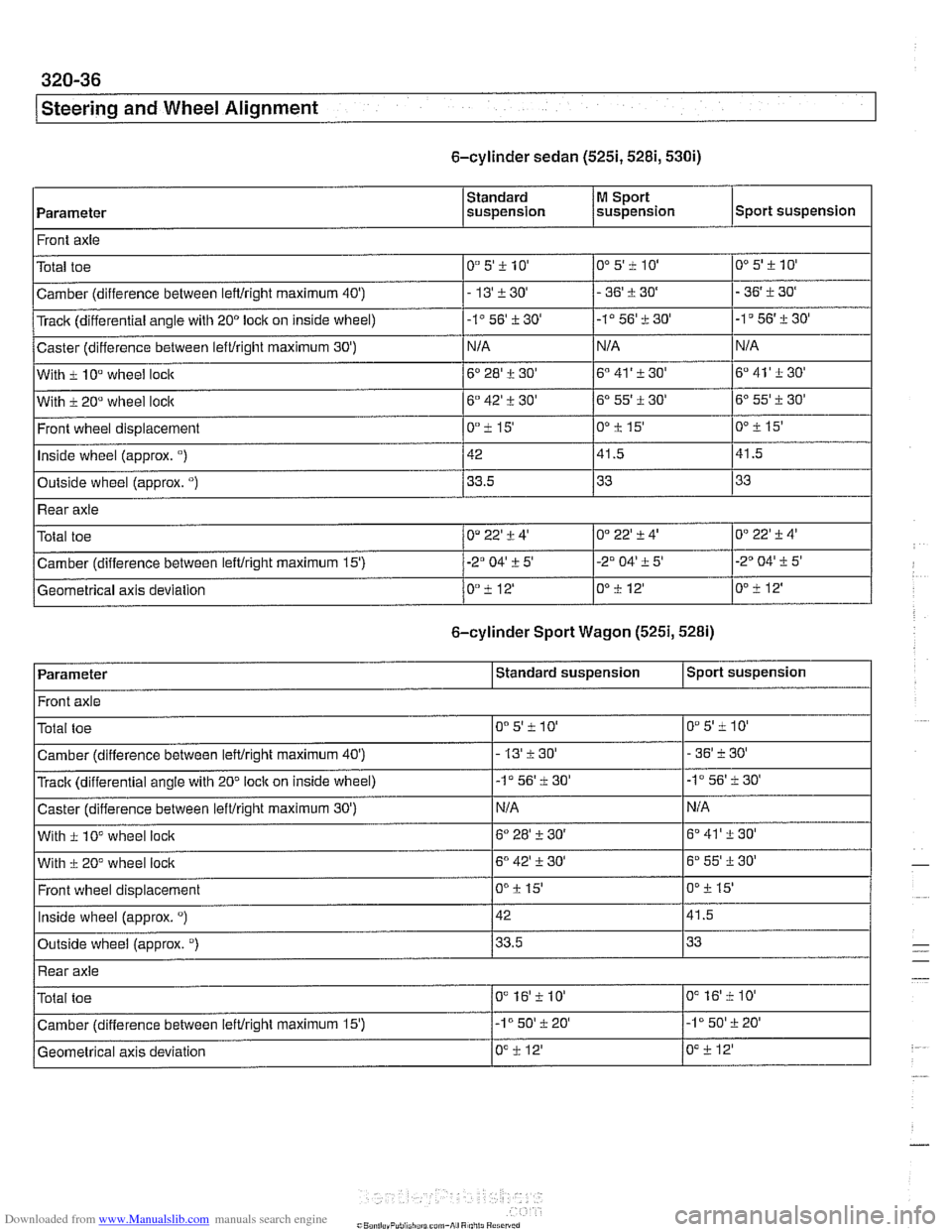
6-cylinder sedan (5251,5281,530i)
Parameter
Front axle
. .. I I I
Outside wheel (approx. ") / 33.5 133 133
M Sport
suspension
Standard
suspension
With
i 20" wheel loclc
Front wheel displacement
Inside wheel
(approx. ")
Sport suspension
O0 5' i 10'
- 36' i 30'
-ID56'-t30'
N/A
6" 41' i 30'
Total toe
Camber (difference between lefffright maximum
40')
Track (differential angle with 20" lock on inside wheel)
Caster (difference between lefffright maximum
30')
With i 10" wheel locic
6" 42' i 30'
0°i15'
42
. .. I I I
Rear axle
6-cylinder Sport Wagon (5251,5281)
0"5'il0'
-13'+30'
-1" 56' -t 30'
N/A
6" 28' i 30'
OD5'i10'
- 36' i 30'
-1" 56' i 30'
N/A
6" 41' i 30'
6" 55'
i 30'
0'2 15'
41.5
0" 22'
-t 4'
0" i 12' Geometrical axis deviation
6' 55' i 30'
0"
i 15'
41.5
0°22'i4' Total toe 0" 22' i 4'
Camber (difference between leitlright maximum 15') 1-20 04' ?- 5' 1-2" 04' i 5'
O"i12'
Sport suspension
Parameter
- I I
. .. I I
Outside wheal (approx. ") 133.5 133
-2' 04' -t 5'
OO-t 12'
Standard suspension
Wlth i 10" wheel lock
I I
Front axle
With
i 20" wheel lock 16" 42' i 30' 16" 55'i30'
6" 28' i- 30'
0"
i 15' Front wheel displacement
. .. I I
Rear axle
D"5'iIO'
- 36' i 30'
-I056'i30'
NIA
Total toe
Camber (difference between
IeWright maximum 40')
Track (differential angle with 20" lock on inside wheel)
Caster (difference between
lefffrioht maximum 30') 6" 41'
+ 30'
Inside wheel (approx. ") 142 141.5
OOi 15'
0"5'i10'
- 13'i30'
-1" 56' i 30'
N/A
0" 16'i 10' Total toe
0" i 12' Geometrical axis deviation
Camber (difference
between iefffright maximum
15') /-lo 50' i 20' 1-1" 50'i20'
0" 16'f 10'
0" il2'
Page 695 of 1002
Downloaded from www.Manualslib.com manuals search engine
Steering and Wheel Alignment
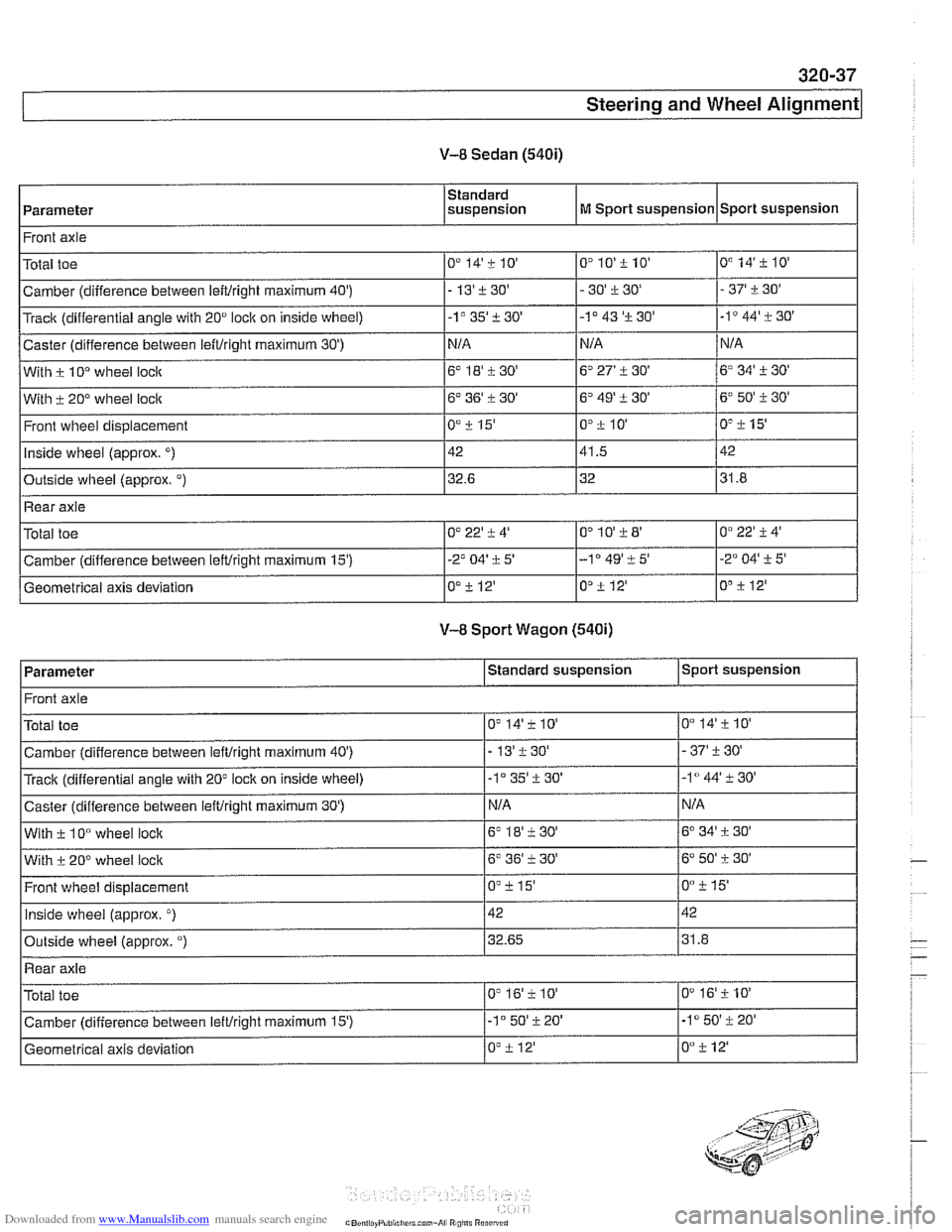
V-8 Sedan (540i)
I Front axle I
Parameter Standard
suspension
Total toe
.
Track (differential angle with 20" ioclc on inside wheel)
Caster (difference between
leftiright maximum 30')
With i 10° wheel loclc
With i 20" wheel lock
Front
wheel displacement
Inside
wheel (approx. ")
Outside wheel (approx. ")
M Sport suspension
Camber (difference between
leitiright maximum 40') 1- 13'i30' 1- 30' i 30' 1- 37' i 30'
0" 10'i 10' 0" 14'ilO'
Sport suspension
0" 14'i 10'
Rear axie
-1°35'i30'
N/A
6" 18'+30'
6' 36' i 30'
0"
i 15'
42
32.6
Total toe
Camber (difference between
IeWright maximum 15')
Geometrical axis deviation ~~
V-8 Sport Wagon (540i)
O"10'iW
-lo 49' i 5'
O"i12'
0" 22' i 4'
-2' 04' i 5'
0"
i 12'
Parameter
-1 " 43 'i 30'
NIA
6" 27'
i 30'
6"49'i30'
Pilo'
41.5
32
0°22'i4'
-2" 04' i 5'
O"i 12'
-ID 44' i 30'
N/A
6" 34' i 30'
6' 50' 130'
0" i 15'
42
31.8
Standard suspension Sport suspension
Front axie
0" 14'210'
-37i30'
-la44'+30'
N/A
6" 34' i 30'
6' 50' i 30'
O0i15'
42
31.8
0"
16'2 10'
-I050'i20'
0" i 12'
Total toe
Camber (difference between
ieftiright maximum 40')
Track (differential angle
with 20" loclc on inside wheel)
Caster (difference between
leftiright maximum 30')
With i 10" wheel lock
With i 20° wheel lock
Front wheel displacement
Inside wheel (approx.
")
Outside wheel (approx. ")
0" 14'i 10'
-13'i30'
-1" 35' i 30'
N/A
6' lS'i30'
6' 36' i 30'
On+ 15'
42 32.65
Rear axle
Total toe
Camber (difference between
lettiright maximum 15')
Geometrical axis deviation
0" 16'i 10'
-I050'i20'
0" i 12'
Page 697 of 1002
Downloaded from www.Manualslib.com manuals search engine
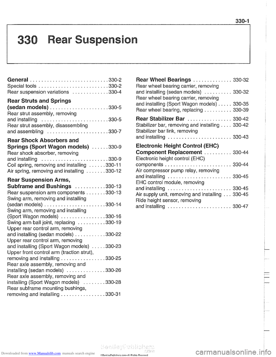
330 Rear Suspension
General . . . . . . . . . . . . . . . . . . . . . . . . . . . ,330-2
Special tools . . . . . . . . . . . . . . . . . . . . . . . . ,330-2
Rear suspension variations . . . . . . . . . . . . ,330-4
Rear Struts and Springs
(sedan models)
. . . . . . . . . . . . . . . . . . . . ,330-5
Rear strut assembly, removing
and installing
. . . . . . . . . . . . . . . . . . . . . . . ,330-5
Rear strut assembly, disassembling
and assembling
. . . . . . . . . . . . . . . . . . . . . ,330-7
Rear Shock Absorbers and
Springs (Sport Wagon models)
. . . . . ,330-9
Rear shock absorber, removing
and installing
. . . . . . . . . . . . . . . . . . . . . . . ,330-9
Coil spring, removing and installing . . . . . ,330-1 1
Air spring, removing and installing
. . . . . . ,330-12
Rear Suspension Arms,
Subframe and Bushings . . . . . . . . . . ,330-13
Rear suspension arm components . . . . . . ,330-1 3
Swing arm, removing and installing (sedan models)
. . . . . . . . . . . . . . . . . . . . . ,330-1 4
Swing arm, removing and installing (Sport Wagon models)
. . . . . . . . . . . . . . . ,330-16
Swing arm ball joint, replacing . . . . . . . . . ,330-1 9
Upper rear control arm, removing
and installing (sedan models)
. . . . . . . . . . .330-22
Upper rear control arm, removing
and installing (Sport Wagon models)
. . . . .330-23
Upper front control arm (traction strut),
removing and installing
. . . . . . . . . . . . . . . ,330-25
Rear axle assembly, removing and
installing (sedan models)
. . . . . . . . . . . . . ,330-26
Rear axle assembly, removing and
installing (Sport Wagon models)
. . . . . . . ,330-28
Rear subframe mounting bushings,
removing and installing
. . . . . . . . . . . . . . . .330-31
Rear Wheel Bearings . . . . . . . . . . .
Rear wheel bearing carrier, removing
and installing (sedan models)
. . . . . . .
Rear wheel bearing carrier, removing
and installing (Sport Wagon models)
. .
Rear wheel bearing, replacing . . . . . . .
Rear Stabilizer Bar
Stabilizer bar, removing and installing .
Stabilizer bar link, removing
and installing
. . . . . . . . . . . . . . . . . . . .
Electronic Height Control (EHC)
Component Replacement
. . . . . . .
Electronic height control (EHC)
components
.....................
Air compressor pump relay, removing
and installing
. . . . . . . . . . . . . . . . . . . .
EHC control module, removing
and installing
. . . . . . . . . . . . . . . . . . . .
Air supply unit, removing and installing
Ride height sensor, removing
and installing
. . . . . . . . . . . . . . . . . . . .
Page 698 of 1002
Downloaded from www.Manualslib.com manuals search engine
330-2
I Rear Suspension
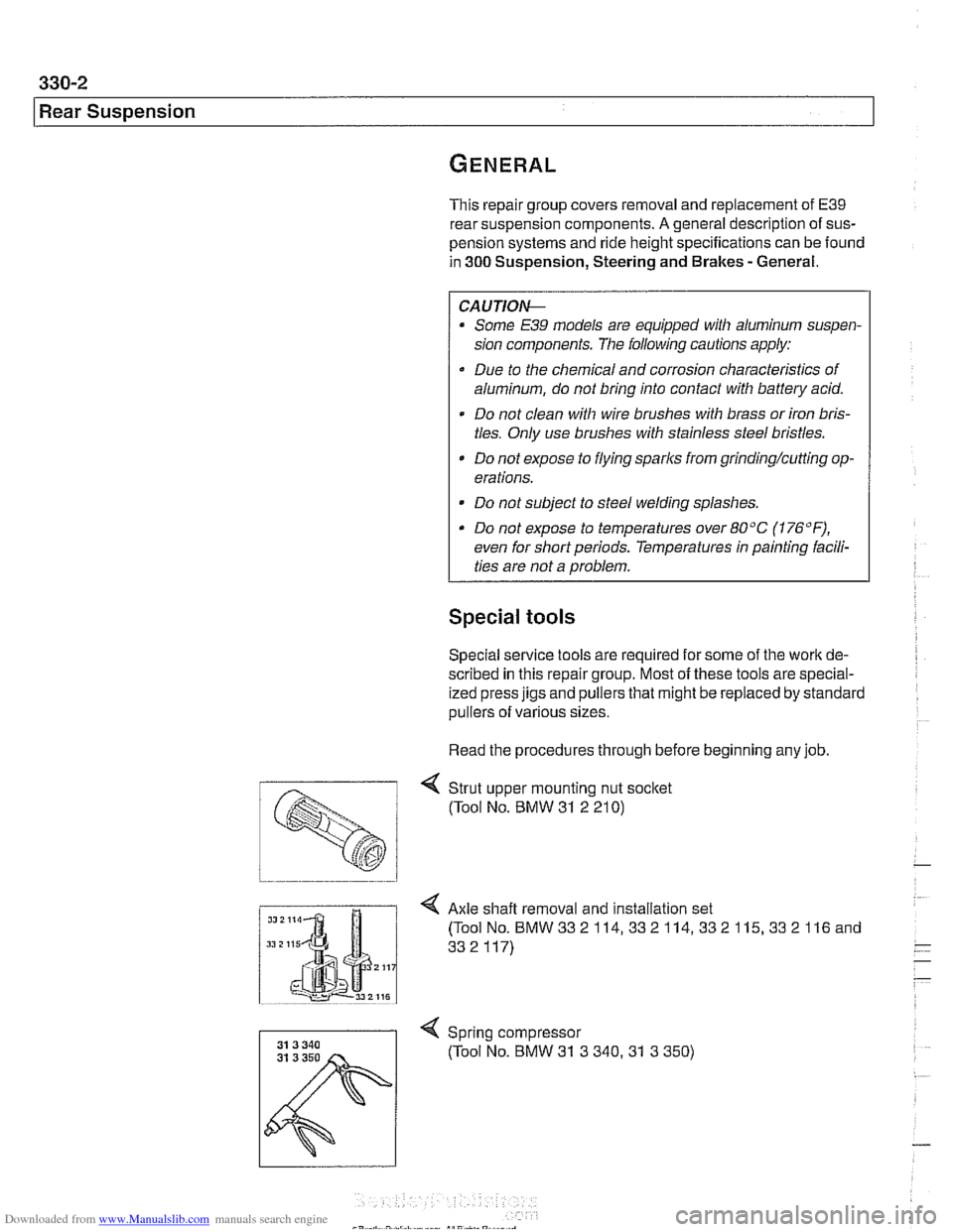
This repair group covers removal and replacement of E39
rear suspension components. A general description of sus-
pension systems and ride height specifications can be found
in 300 Suspension, Steering and Brakes - General.
CAUTIOI\C
Some E39 models are equipped with aluminum suspen-
sion components. The following cautions apply:
Due to the chemical and corrosion characteristics of
aluminum, do not bring into contact with battery acid.
- Do not clean with wire brushes with brass or iron bris-
tles. Only use brushes with stainless steel bristles.
Do not expose to flying
sparl~s from grinding/cutting op-
erations.
* Do not subject to steel welding splashes.
0 Do not expose to temperatures over 80°C (176°F).
even for shortperlods. Temperatures in painting facili-
ties are not a problem.
Special tools
Special service tools are required for some of the work de-
scribed in this repair group. Most of these tools are special-
ized press jigs and pullers that might be replaced by standard
pullers of various sizes.
Read the procedures through before beginning any job.
< Strut upper mounting nut socket
(Tool No. BMW
31 2 21 0)
I Axle shaft removal and installation set
Spring compressor (Tool No. BMW
31 3 340.31 3 350)
Page 699 of 1002
Downloaded from www.Manualslib.com manuals search engine
Rear suspension/
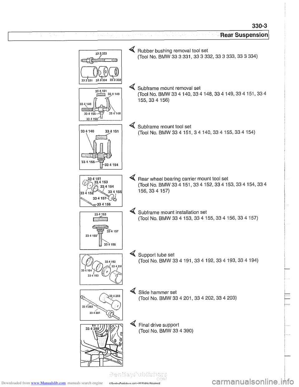
31 3 333 "I Rubber bushing removal tool set
(Tool No. BMW
33 3 331,33 3 332,33 3 333,33 3 334)
4 Subframe mount removal set
(ToolNo.BMW334 140,334148,334149,334151,334
155.33 4 156)
4 Subirame mount tool set
(Tool
No.BMW334151,34140,334155,334154)
4 Rear wheel bearing carrier mount tool set
(ToolNo.BMW334151,334152,334153,334154,334
156,334157)
4 Subframe mount installation set
(Tool No. BMW
33 4 153,33 4 155,33 4 156,33 4 157)
Slide hammer set
(Tool No. BMW
33 4 201,33 4 202,33 4 203)
13 4 201
Page 700 of 1002
Downloaded from www.Manualslib.com manuals search engine
330-4
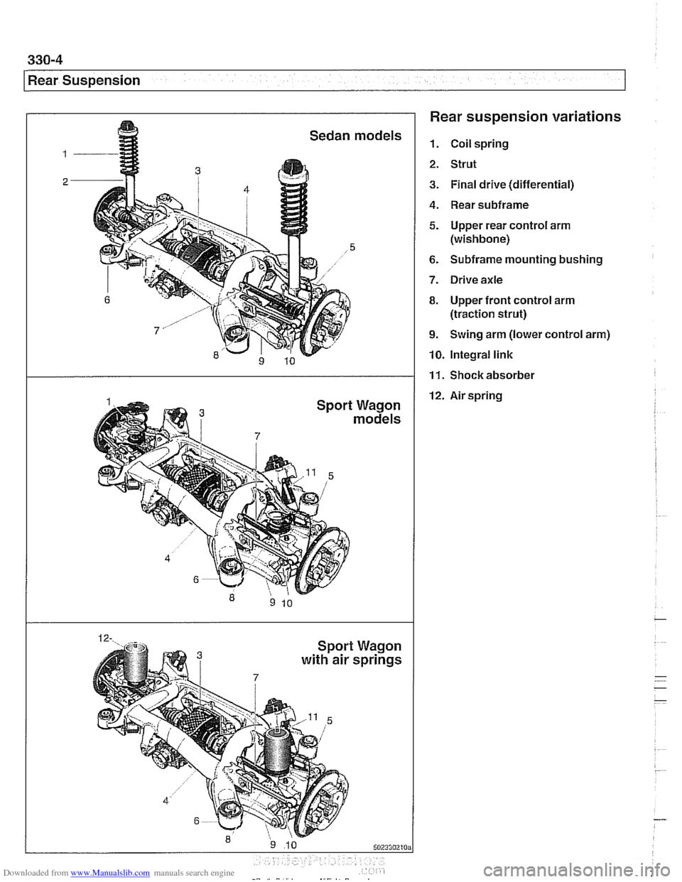
Rear Suspension Rear suspension variations
1. Coil spring
2. Strut
3. Final drive (differential)
4. Rear subframe
5. Upper rear control arm
(wishbone)
6. Subframe mounting bushing
7. Drive axle
8. Upper front control arm
(traction strut)
9. Swing arm (lower control arm)
10. Integral link
12. Air spring
I
Waaon
11. Shockabsorber
a m3 withair s~riias
Page 701 of 1002
Downloaded from www.Manualslib.com manuals search engine
330-5
Rear Suspension
REAR STRUTS AND SPRINGS
(SEDAN MODELS)
Rear strut assembly, removing and
installing
Replace struts and coil springs in pairs only.
- Raise car and remove rear wheels.
WARNING -
Male sure the car is firmly supported on jack stands de-
signed for the purpose. Place jack stands underneath struc-
tural chassis points. Do not place jack stands under
suspension parts.
- Remove rear parcel shelf:
Remove rear seat headrests by pulling straight up.
Remove both rear roof pillar (C-pillar) trim panels.
Unbolt rear seat
belt anchors. See 720 Seat Belts.
Models with fixed rear seat: Remove rear seat backrest.
See 520 Seats.
* Models with fold-down rear seat: Remove rear seat back-
rest side sections. See 520 Seats. Fold down backrest.
* Working inside trunk, remove roller blind mounting nuts
and bolts, if applicable. Also disconnect roller blind har-
ness connector at right edge of rear seat backrest.
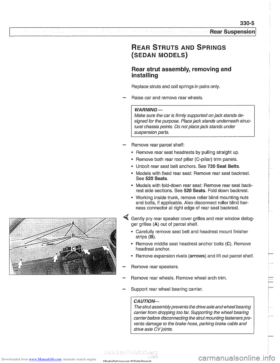
Gently pry rear speaker cover grilles and rear window defog-
ger grilles
(A) out of parcel shelf.
Carefully remove seat belt and headrest mount finisher
strips (B).
Remove
middle seat headrest anchor bolts (C). Remove
headrest anchor.
Remove expansion rivets (arrows) and lift out parcel shelf.
- Remove rear speakers.
- Remove rear wheels. Remove wheel arch trim
- Support rear wheel bearing carrier.
CAUTION-
The strutassembly prevents the drive axle and wheel bearing
carrier
from dropping too far. Supporting the wheel bearing
carrierbefore disconnecting the strut mounting fasteners pre-
vents damage to the brake hose, parking brake cable and
drive axle
CV joints.
Page 702 of 1002
Downloaded from www.Manualslib.com manuals search engine
330-6
Rear Suspension
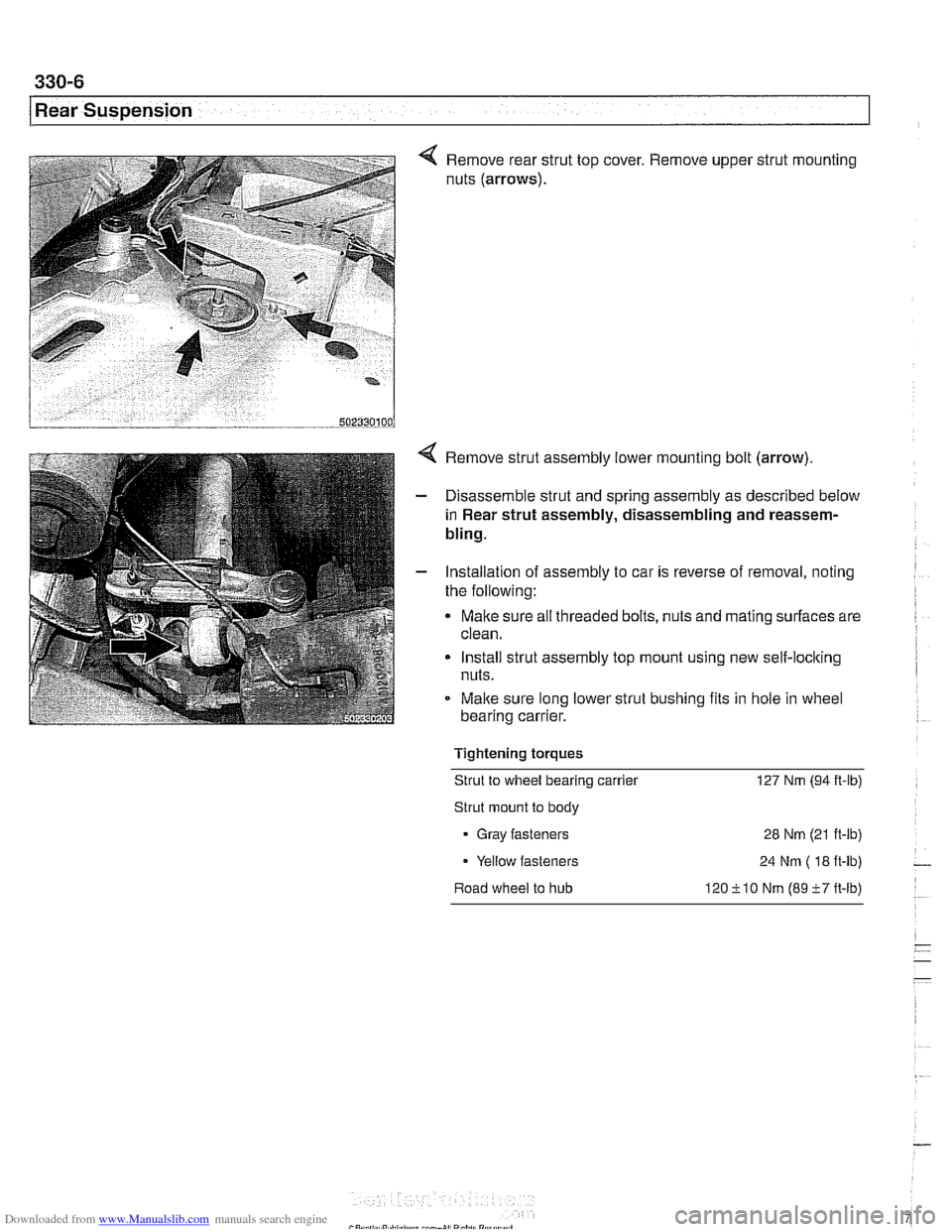
4 Remove rear strut top cover. Remove upper strut mounting
nuts (arrows).
Remove strut assembly lower mounting bolt (arrow).
Disassemble strut and spring assembly as described below
in Rear strut assembly, disassembling and reassem-
bling.
Installation of assembly to car is reverse of removal, noting
the following:
Make sure all threaded bolts, nuts and mating surfaces are
clean.
Install strut assembly top mount using new self-loclting
nuts.
Malte sure long lower strut bushing fits in
hole in wheel
bearing carrier.
Tightening torques Strut to wheel bearing carrier 127 Nm (94
it-lb)
Strut mount to body
Gray fasteners 28 Nm (21 ft-lb)
Yellow fasteners 24 Nm
( 18 it-lb) -
Road wheel to hub 120ilO Nm (89i7ft-lb)
Page 703 of 1002
Downloaded from www.Manualslib.com manuals search engine
Rear ~us~ensionl
Rear strut assembly, disassembling and
assembling
Replace struts and coil springs in pairs only
Replacing the upper strut mount, spring or strut requires that
the strut assembly first be removed from the car, as described
earlier. Strut disassembly requires a spring compressor.
WARNING-
Do not attempt to disassemble the strut without a spring com-
pressor designed specifically for the job.
- Remove strut assembly from car as described in Rear strut
assembly, removing
bnd installing
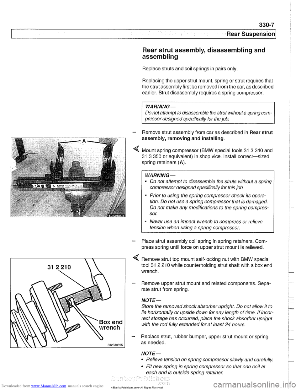
4 Mount spring compressor (BMW special tools 31 3 340 and
31 3 350 or equivalent) in shop vice. Install correct-sized
spring retainers
(A).
WARNING-
Do not attempt to disassemble the struts without a spring
compressor designed specifically for this job.
* Prior to using the spring compressor checlc its opera-
tion. Do not use a spring compressor that is damaged.
Do not make any modifications to the spring compres-
sor.
Never use an impact wrench to compress or relieve
tension when using a spring compressor.
1
- Place strut assembly coil spring in spring retainers. Com-
press spring until force on upper strut mount is relieved.
Remove strut top mount self-locking nut with BMW special
tool
31 2 21 0 while counterholding strut shaft with a box end
wrench.
- Remove upper strut mount and related components. Sepa-
rate strut from spring.
NOTE-
Store the removed shock absorber upright Do not allow it to
lie horizontally or upside down for any length of time. If incor-
rect storage has occurred, place the
shoclc absorber upright
with the rod
fully extended for at least 24 hours.
- Replace strut, rubber bumper, upper strut mount or spring,
as needed.
NOTE- Relieve tension on spring compressor slowly and carefully.
Fit new spring in spring compressor so that one coil at
each end is outside spring retainer.
Page 704 of 1002
Downloaded from www.Manualslib.com manuals search engine
330-8
Rear Suspension
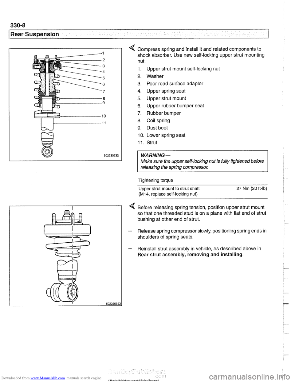
4 Compress spring and install it and related components to
shock absorber. Use new self-locking upper strut mounting
nut.
1. Upper strut mount self-locking nut
2. Washer
3. Poor road surface adapter
4. Upper spring seat
5. Upper strut mount
6. Upper rubber bumper seat
7. Rubber bumper
8. Coil spring
9. Dust boot
10. Lower spring seat
I I. Strut
WARNING-
Male sure the upperself-locking nut is fully tightened before
releasing the spring compressor.
Tightening torque
Upper strut mount to strut shaft
27 Nm (20 ft-lb)
(M14, replace self-locking nut)
4 Before releasing spring tension, position upper strut mount
so that one threaded stud is on a plane with flat end of strut
bushing at other end of strut.
- Release spring compressorslowly, positioning spring ends in
shoulders of spring seats.
- Reinstall strut assembly in vehicle, as described above in
Rear strut assembly, removing and installing.