rear BMW 525i 1997 E39 Workshop Manual
[x] Cancel search | Manufacturer: BMW, Model Year: 1997, Model line: 525i, Model: BMW 525i 1997 E39Pages: 1002
Page 608 of 1002
Downloaded from www.Manualslib.com manuals search engine
260-2
1 Driveshaft
This repair group covers repair and replacement of the
driveshaft and driveshaft components.
Driveshaft repairs consist of replacement of front flex-disc.
center mount or rear
CV joint. If the driveshaft joint is defec-
tive, replace the complete driveshaft.
Drive axle repairs are covered in
331 Final Drive
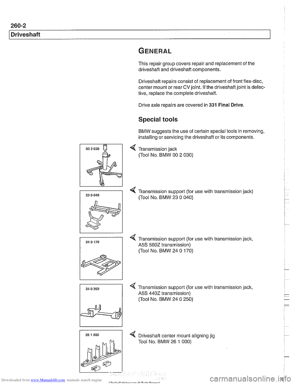
Special tools
BMW suggests the use of certain special tools in removing,
installing or servicing the driveshaft or its components.
4 Transmission jack
(Tool No. BMW 00 2 030)
4 Transmission support (for use with transmission jack)
/ (Tool NO. BMW 23 0 040)
24 0 170
1
4 Transmission support (for use with transmission jack,
A5S 560Z transmission)
(Tool No. BMW 24
0 170)
24 0 250
I
4 Transmission support (for use with transmission jack,
A5S
4402 transmission)
(Tool No. BMW 24
0 250)
4 Drlveshaft center mount allgnlng yg
Tool No. BMW 26 1 000)
Page 609 of 1002
Downloaded from www.Manualslib.com manuals search engine
Driveshaft
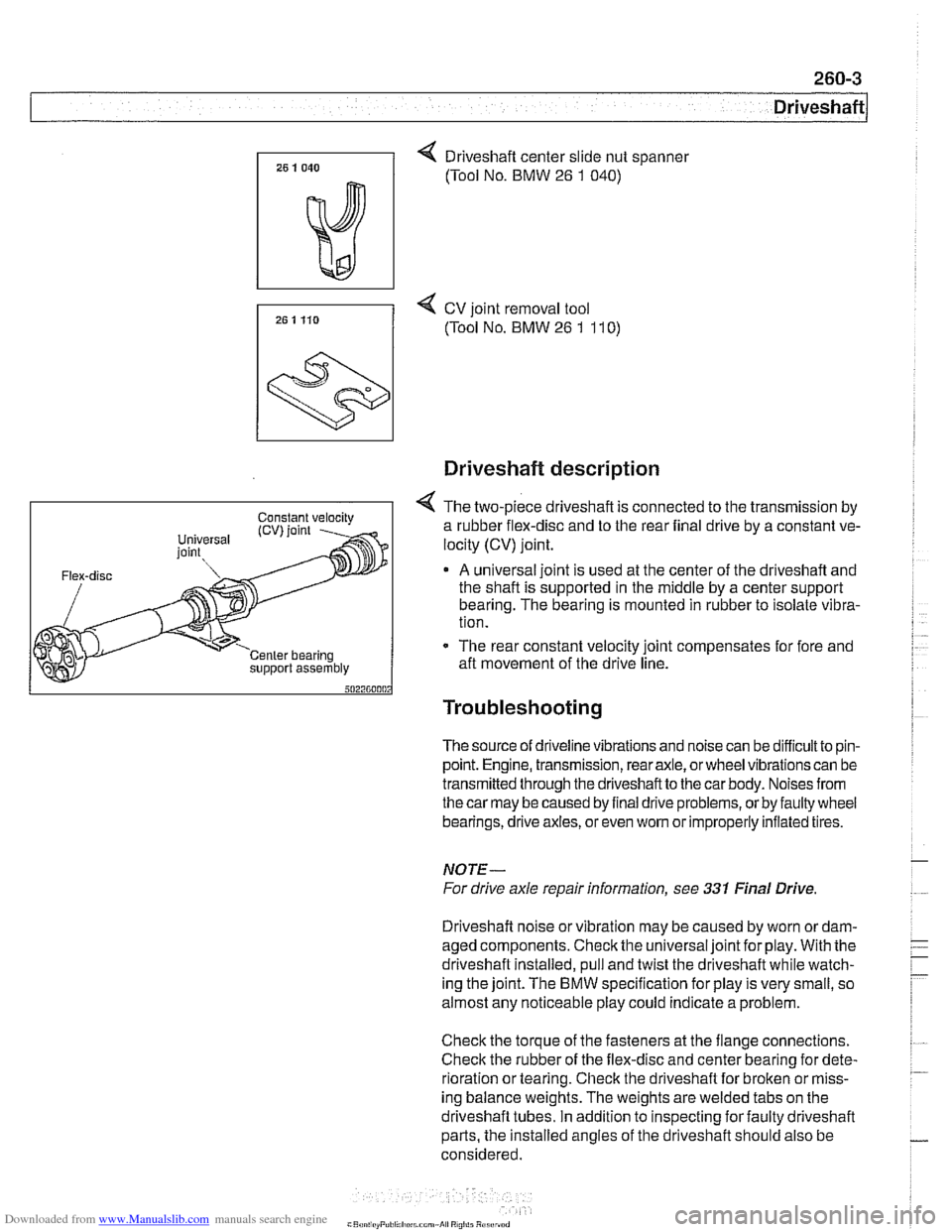
4 Driveshaft center slide nut spanner
(Tool No. BMW
26 1 040)
7, 25 1 Ho 4 cv joint removal tool
(Tool No. BMW 26 1 11 0)
support assembly
Driveshaft description
4 The two-piece driveshaft is connected to the transmission by
a rubber flex-disc and to the rear final drive by a constant ve-
locity (CV) joint.
A universal joint is used at the center of the driveshaft and
the shaft is supported in the middle by a center support
bearing. The bearing is mounted in rubber to isolate vibra-
tion.
- The rear constant velocity joint compensates for fore and
aft movement of the drive line.
Troubleshooting
The source of driveline vibrations and noise can be difficultto pin-
point. Engine, transmission, rear axle, or wheel vibrations can be
transmitted through thedriveshaftto the car body. Noises from
thecar may be caused by final drive problems, or by faulty wheel
bearings, drive axles, or even
wom or improperly inflated tires.
NOTE-
For drive axle repair information, see 331 Final Drive
Driveshaft noise or vibration may be caused by worn
ordam-
aged components. Check the universal joint for play. With the
driveshaft installed, pull and twist the driveshaft while watch-
ing the joint. The
BMW specification for play is very small, so
almost any noticeable play could indicate a problem.
Check the torque of the fasteners at the flange connections.
Check the rubber of the flex-disc and center bearing for dete-
rioration or tearing. Check the driveshaft for broken or miss-
ing balance weights. The weights are welded tabs on the
driveshaft tubes. In addition to inspecting for faulty driveshaft
parts, the installed angles of the driveshaft should also be
considered.
Page 612 of 1002
Downloaded from www.Manualslib.com manuals search engine
Driveshaft
Repair kits for the universal joint are not available for BMW
driveshafts.
A worn or damaged universal joint usually require
replacement of the driveshaft.
The driveshaft is balanced to close tolerances. Whenever it is
to be removed or disassembled, the mounting flanges and
driveshaft sections should be marked with paint or a punch
before proceeding with work. This will ensure that the
drive-
shaft can be reassembled and installed in exactly the original
orientation.
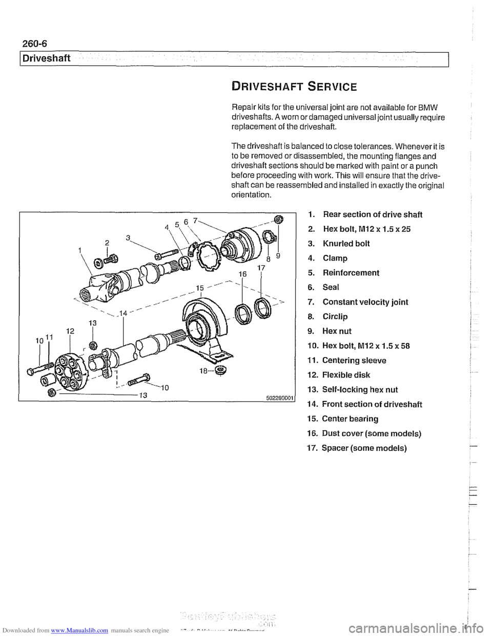
1. Rear section of drive shaft
2. Hex bolt, MI2 x 1.5 x 25
3. Knurled bolt
4. Clamp
5. Reinforcement
6. Seal
7. Constant velocity joint
8. Circlip
9. Hex nut
10. Hex bolt, M12x 1.5~58
11. Centering sleeve
12. Flexible disk
13. Self-locking hex nut
14. Front section of driveshaft
15. Center bearing
16. Dust cover (some models)
17. Spacer (some models) -
Page 613 of 1002
Downloaded from www.Manualslib.com manuals search engine
Driveshaft, aligning
The alignment of the driveshaft does not normally need to be
checked unless the engineltransmission or the final drive
have been removed and installed. if ail other parts of the
driveshaft have been inspected and found to be okay, but
there is still noise or vibration, driveshaft alignment should be
checked.
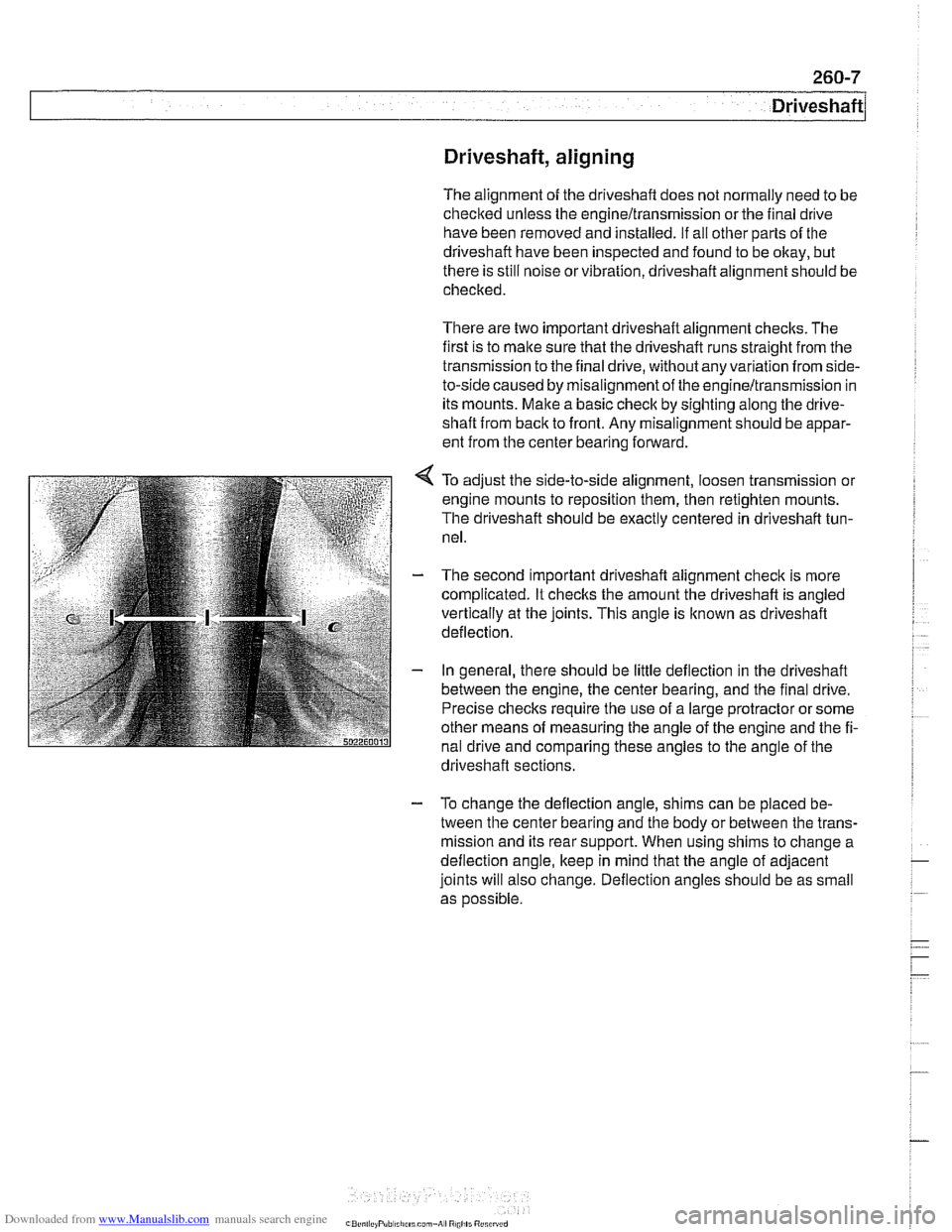
There are two important driveshaft alignment checks. The
first is to make sure that the driveshaft runs straight from the
transmission to the final drive, without any variation from
side-
to-side caused by misalignment of the engineltransmission in
its mounts. Make a basic check by sighting along the
drive-
shaft from back to front. Any misalignment should be appar-
ent from the center bearing forward.
To adjust the side-to-side alignment, loosen transmission or
engine mounts to reposition them, then retighten mounts.
The driveshaft should be exactly centered in driveshaft tun-
nel.
The second important driveshaft alignment check is more
complicated. It checlts the amount the driveshaft is angled
vertically at the joints. This angle is
lknown as driveshaft
deflection.
In general, there should be little deflection in the driveshaft
between the engine, the center bearing, and the final drive.
Precise checks require the use of a large protractor or some
other means of measuring the angle of the engine and the fi-
nal drive and comparing these angles to the angle of the
. . driveshaft sections.
- To change the deflection angle, shims can be placed be-
tween the center bearing and the body or between the trans-
mission and its rear support. When using shims to change a
deflection angle, keep in mind that the angle of adjacent
joints will also change. Deflection angles should be as small
as
oossible.
Page 614 of 1002
Downloaded from www.Manualslib.com manuals search engine
-.- .
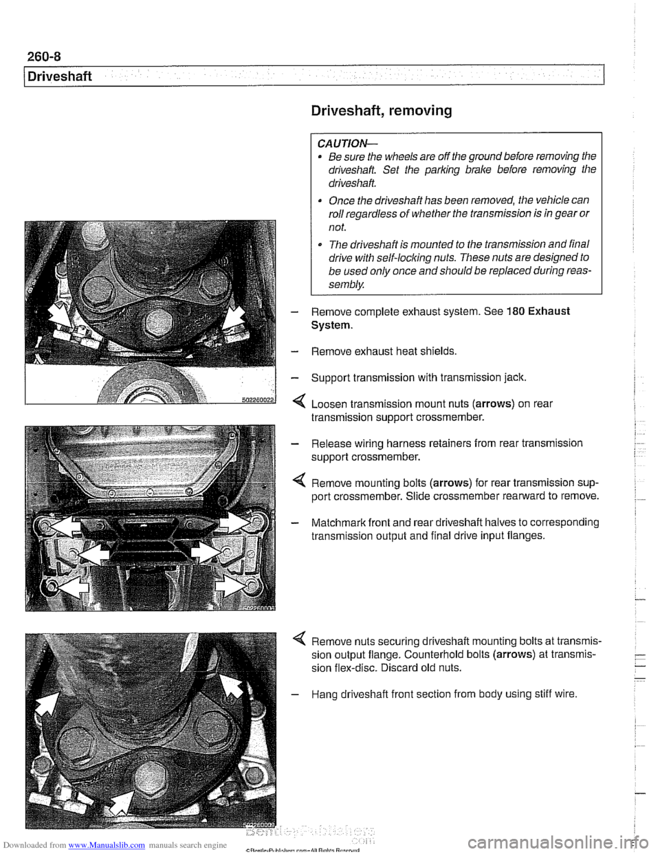
/ Driveshaft Driveshaft, removing
CAUTION-
. Be sure the wheels are off the ground before removing the
driveshak Set the parl(ing brake before removing the
driveshaft.
Once the driveshaft has been removed, the vehicle can
roll regardless of whether the transmission is in gear or
not.
The driveshaft is mounted to the transmission and final
drive
with self-locliing nuts. These nuts are designed to
be used only once and should be replaced during reas-
sembly.
Remove complete exhaust system. See
180 Exhaust
System.
- Remove exhaust heat shields.
- Support transmission with transmission jack.
< Loosen transmission mount nuts (arrows) on real
transmission support crossmember.
- Release wiring harness retainers from rear transmission
support crossmember.
< Remove mounting bolts (arrows) for rear transmission sup-
port crossmember. Slide crossmember rearward to remove.
- Matchmark front and rear driveshaft halves to corresponding
transmission output and final drive input flanges.
4 Remove nuts securing driveshaft mounting bolts at transmis-
sion output flange. Counterhold bolts (arrows) at transmis-
sion flex-disc. Discard old nuts.
- Hang driveshaft front section from body using stiff wire.
Page 615 of 1002
Downloaded from www.Manualslib.com manuals search engine
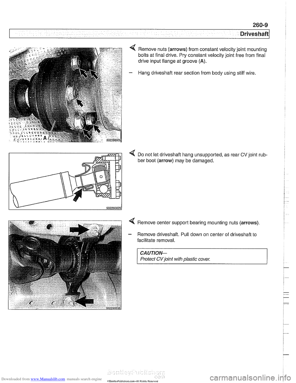
4 Remove nuts (arrows) from constant velocity joint mounting
bolts at final drive. Pry constant velocity joint free from final
drive input flange at groove
(A).
- Hang driveshaft rear section from body using stiff wire.
< Do not let driveshaft hang unsupported, as rear CV joint rub-
ber boot (arrow) may be damaged.
4 Remove center support bearing mounting nuts (arrows)
- Remove driveshaft. Pull down on center of driveshaft to
facilitate removal.
CAUTIOI\C
Protect CVjoint with plastic cover.
Page 616 of 1002
Downloaded from www.Manualslib.com manuals search engine
260-1 0
/ Driveshaft
Driveshaft, installing
- Prepare CV joint for reinstallation:
Extend joint to limit.
Clean off old grease and fill with fresh grease
Install new seal.
- Bend driveshaft slightly at center universal joint to install
CAUTION-
Do not allow CVjoint seal to become displaced.
- Align matchmarlts on driveshaft to matchmarks on final drive
and transmission flanges.
- Fit constant velocity joint to final drive input flange. Alternate-
ly tighten two opposite nuts to draw constant velocity joint
evenly into the final drive input flange. Once seated, tighten
down remaining nuts.
I CAUTION-
I Do not reuse self-locking nuts. These nuts are designed to be /
I used onlv once. 1
- Insert bolts in front of driveshafl to transmission output
flange. Counterhold each bolt while tightening nut.
CAUTION-
. Do not reuse self-locking nuts. These nuts are designed to
be used only once.
Avoid stressing the flex-disc when torquing the bolts.
Do this by counterholding the bolts and turning the nuts
on the flange side.
- Position center support bearing and install mounting nuts.
Use new self-locking nuts.
- Install heat shields.
- Install rear transmission support crossmember.
- Install exhaust system. See 180 Exhaust System.
Reconnect oxygen sensor wiring harnesses and reattach
wiring harness retainers to rear transmission support
crossrnernber.
Page 618 of 1002
Downloaded from www.Manualslib.com manuals search engine
260-1 2
1 Driveshaft
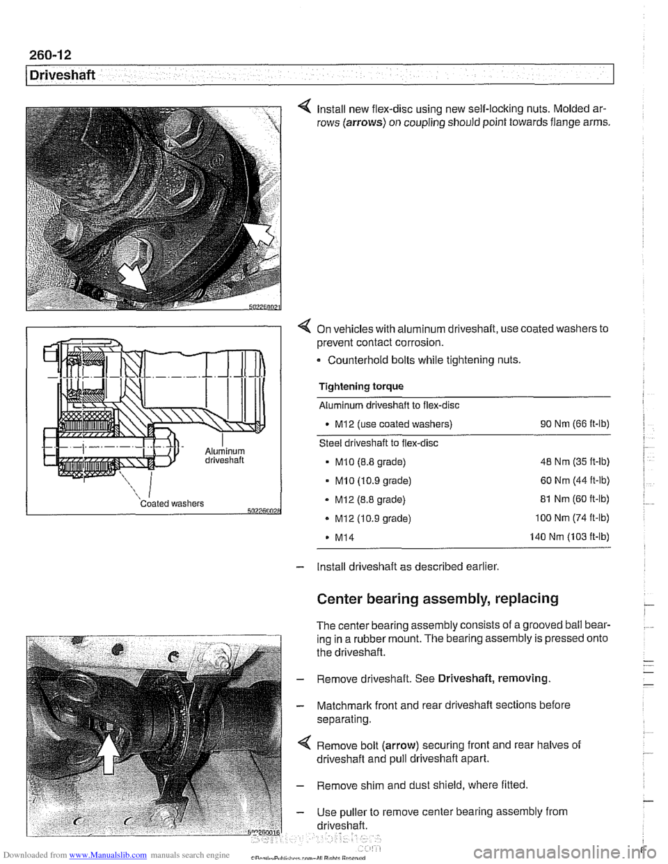
Install new flex-disc using new self-locking nuts. Molded ar-
rows (arrows) on coupling should point towards flange arms.
4 On vehicles with aluminum driveshaft, use coated washers to
prevent contact corrosion.
- Counterhold bolts while tightening nuts.
Tightening torque
Aluminum driveshaft to flex-disc
M12 (use coated washers) 90
Nm (66 ft-lb)
Steel driveshaft to flex-disc
MI0 (8.8 grade) 48
Nm (35 ft-lb)
- MI0 (10.9 grade) 60 Nm (44 ft-lb)
Coated washers - MI2 (8.8 grade) 5027500 . Mi2 (10.9 grade)
M14 81
Nm (60 ft-lb) 100 Nm (74 ft-lb)
140 Nm (103 ft-lb)
- Install driveshaft as described earlier
Center bearing assembly, replacing
The center bearing assembly consists of a grooved ball bear-
ing in a rubber mount. The bearing assembly is pressed
the driveshaft.
- Remove driveshaft. See Driveshaft, removing
- Matchmark front and rear driveshaft sections before
separating.
Remove bolt (arrow) securing front and rear halves of
driveshaft and pull driveshaft apart.
- Remove shim and dust shield, where fitted
- Use puller to remove center bearing assembly from
driveshaft. onto
Page 619 of 1002
Downloaded from www.Manualslib.com manuals search engine
- On installation, drive new center bearing firmly to stop.
Reassemble driveshaft using matchmarks made prior to
disassembly.
- Clean threads and install bolt securing driveshaft halves.
Use thread locking compound
LoctiteO or equivalent.
Tightening torque Driveshaft front half to rear half
(use thread locking compound) 97
Nm (72 fl-lb)
- Install driveshaft as described earlier.
Front centering guide, replacing
The front centering guide centers the driveshafl in relation to
the transmission. The guide is press-fit into a cavity in the
front of the driveshafl and slides onto the transmission output
shaft.
No specifications are given
forwear of the guide, but general-
ly the guide should fit snugly on the transmission output shafl.
NOTE-
Some driveshafts have a dust cap installed on the end of the
driveshaft, over the centering guide. The dust cap may be-
come bent or distorted when the driveshaft is removed or
in-
stalled. Damage to the dust cap should not affect the
centering guide and should not be mistaken for guide wear.
- Remove driveshafl as described earlier
- Pack cavity behind centering guide with heavy grease until
grease is flush with bottom edge of guide.
- Insert 14 mm (approximately 9/16 in.) diameter mandrel or
metal rod into guide. Strike guide with hammer to force cen-
tering guide out.
NOTE-
Tlie mandrel should fit snugly in the centering guide so that
the grease cannot escape around the sides of the mandrel.
- Remove old grease from driveshaft, lubricate new centering
guide with molybdenum disulfide grease
(MolykoteO, Long-
term8 2 or equivalent) and drive it into driveshaft.
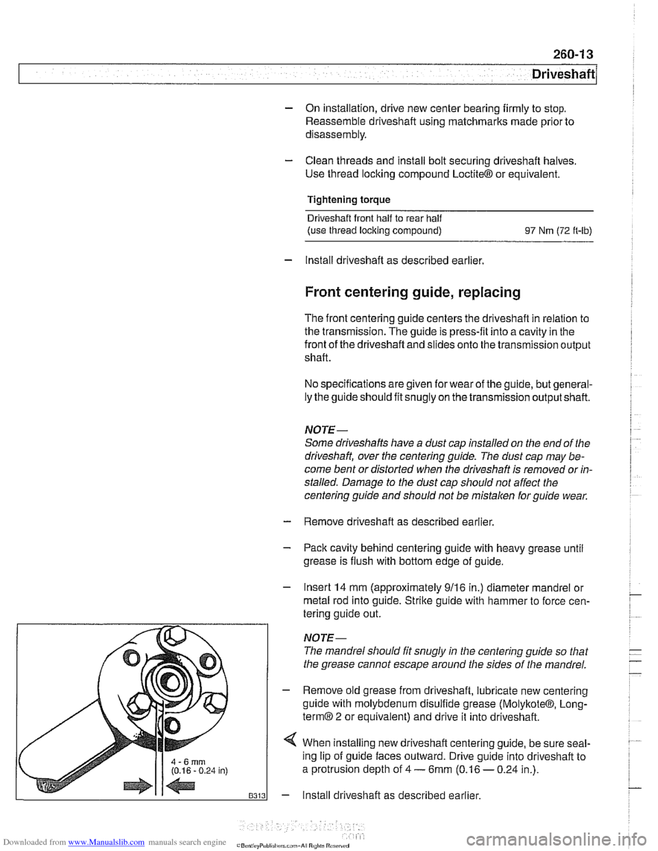
4 When installing new driveshafl centering guide, be sure seal-
ing lip of guide faces outward. Drive guide into driveshaft to
a protrusion depth of
4 - 6mm (0.16 - 0.24 in.).
- Install driveshaft as described earlier.
Page 620 of 1002
Downloaded from www.Manualslib.com manuals search engine
260-14
Driveshaft
Constant velocity (CV) joint, replacing
The CV joint at the rear of the driveshaft is available from
BMW as a separate part.
- Remove complete driveshaft as described earlier in this
section.
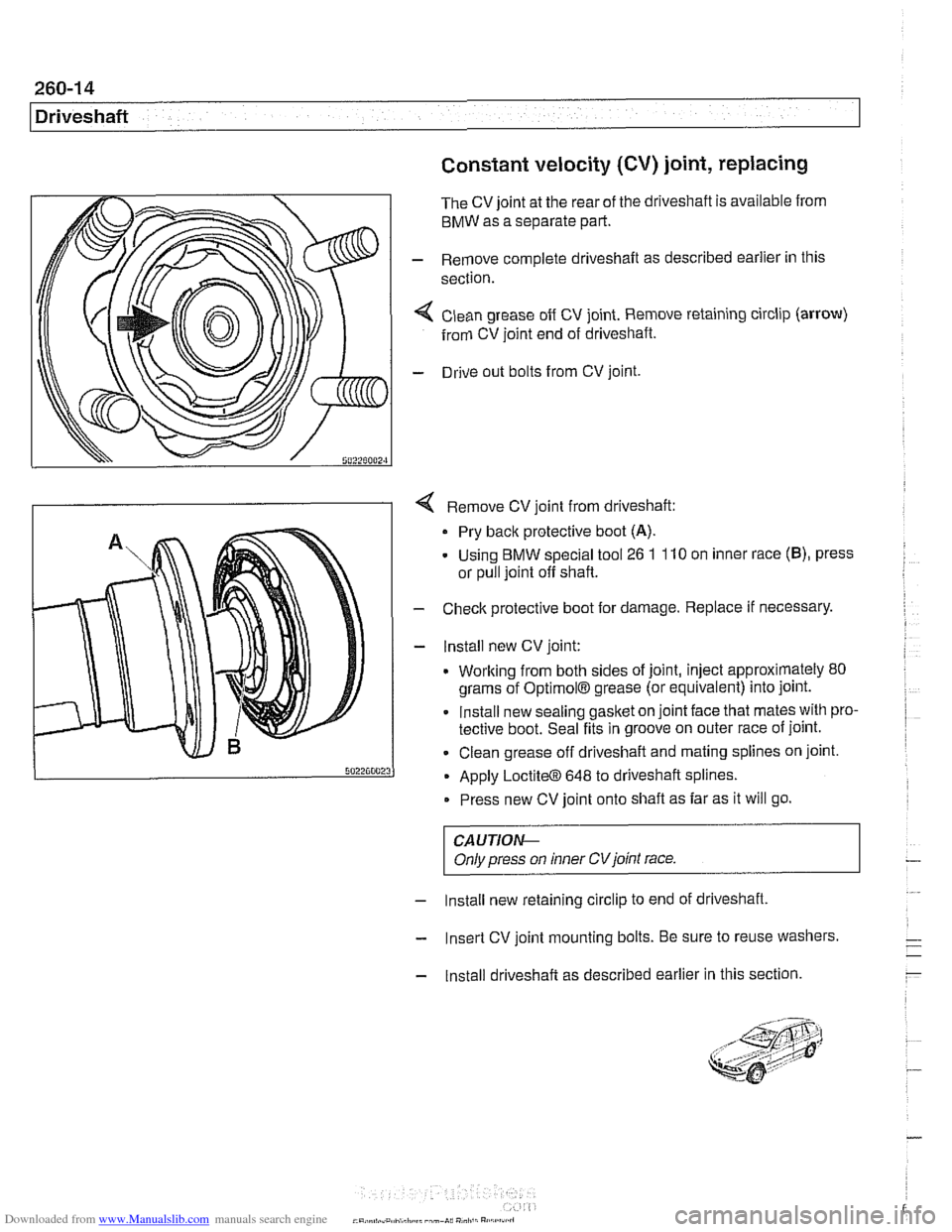
< Clean grease off CV joint. Remove retaining circlip (arrow)
from CV joint end of driveshaft.
- Drive out bolts from CV joint.
4 Remove CV joint from driveshaft:
Pry back protective boot
(A).
- Using BMW special tool 26 1 110 on inner race (B), press
or pull joint off shaft.
- Check protective boot for damage. Replace if necessary.
- lnstall new CV joint:
. Working from both sides of joint, inject approximately 80
grams of
OptimolB grease (or equivalent) into joint.
Install new sealing gasket on joint face that mates with pro-
tective boot. Seal fits in groove on outer race of joint.
Clean grease off driveshaft and mating splines on joint.
Apply
LoctiteO 648 to driveshaft splines.
Press new CV joint onto shaft as far as it will go.
CAUTIOI\C
Only press on inner CVjoint race.
- Install new retaining circlip to end of driveshaft,
- Insert CV joint mounting bolts. Be sure to reuse washers.
- Install driveshaft as described earlier in this section.