ECO BMW 525i 1997 E39 Workshop Manual
[x] Cancel search | Manufacturer: BMW, Model Year: 1997, Model line: 525i, Model: BMW 525i 1997 E39Pages: 1002
Page 528 of 1002
Downloaded from www.Manualslib.com manuals search engine
180-6
Exhaust System
Exhaust manifolds, removing and installing
(M52 TU and M54 engines)
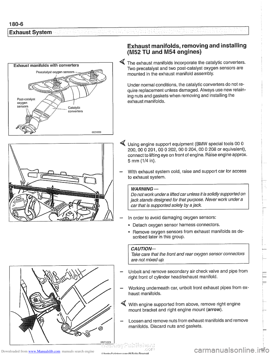
I Exhaust manifolds with converters I 4 The exhaust manifolds incorporate the catalytic converters.
Two precatalyst and two post-catalyst oxygen sensors are
mounted in the exhaust manifold assembly.
Under normal conditions, the catalytic converters do not re-
quire replacement unless damaged. Always use new retain-
ing nuts and gaskets when removing and installing the
exhaust manifolds.
I\
1 4 Using engine support equipment (BMW special tools 00 0
200. 00 0 201. 00 0 202.00 0 204.00 0 208 or equivalent).
connect to
lifting eye on front of engine. Rhise engine approx.
/I 1
5 mm (IH in).
With exhaust system cold, raise and support car for access
to exhaust system.
WARNING-
Do not worlc undera liftedcar unless it is solidly supported on
jack stands designed for that purpose. Never worlc under
a
car that is supported solely by a jaclc.
in order to avoid damaging oxygen sensors:
- Detach oxygen sensor harness connectors,
Remove oxygen sensors from exhaust manifolds as de-
scribed later in this group.
Unbolt and remove secondary air
checkvalve and pipe from
right front of cylinder headlexhaust manifold.
Working underneath car, unbolt front exhaust pipes from ex.
haust manifolds.
With engine supported from above, remove right engine
mount
bracket and right engine mount (arrow).
Loosen and remove nuts from exhaust manifolds and remove
manifolds. Discard nuts and gaskets.
CA UTIOG
Take care tliat the front and rear oxygen sensor connectors
are not mixed up.
-
Page 531 of 1002
Downloaded from www.Manualslib.com manuals search engine
-- -
Exhaust System
Oxygen sensors (precatalyst), replacing
(M52 TU and M54)
The precatalyst oxygen sensors are installed at the top of the
exhaust manifolds.
WARNING-
Allow components to cool before servicing.
- Using BMW scan tool DlSplus (Diagnostic Information Sys-
tem) or equivalent, read out and clear ECM fault codes.
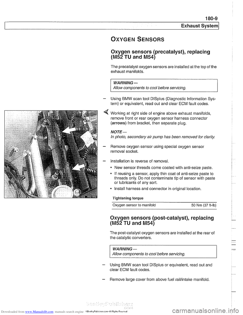
Working at right side of engine above exhaust manifolds,
remove front or rear oxygen sensor harness connector
(arrows) from bracket, then separate plug.
NOTE-
In photo, secondary air pump has been removed for clarity.
Remove oxygen sensor using special oxygen sensor
removal socket.
Installation is reverse of removal
New sensor threads come coated with anti-seize paste.
If reusing a sensor, apply thin coat of anti-seize paste to
threads only. Do not contaminate tip of sensor with paste
or lubricants of any sort.
Install harness and connector in original location.
Tightening torque
- -.
Oxygen sensor to manifold 50 Nm (37 ft-lb)
Oxygen sensors (post-catalyst), replacing
(M52 TU and M54)
The post-catalyst oxygen sensors are installed at the rear of
the catalytic converters.
WARNING-
Allow components to cool before servicing
- Using BMW scan tool DlSplus or equivalent, read out and
clear ECM fault codes.
- Remove large cover from above fuel raillintake manifold.
Page 551 of 1002
Downloaded from www.Manualslib.com manuals search engine
- Raise and safely support vehicle
WARNING-
Make sure the car is stable and well supporied at all times.
Use a professional automotive /iff orjack stands designed for
the
ournose. A floor jack is not adeouate suooort.
- If necessary, remove transmission splash shield.
- Disconnect fluid line from slave cylinder on lefl side of trans-
mission. Place pan under hose to catch dripping fluid.
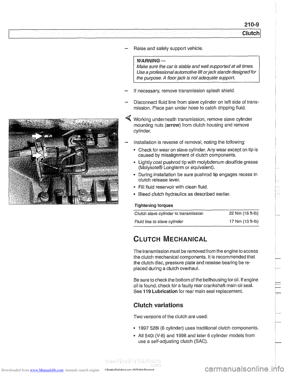
4 Working underneath transmission, remove slave cylinder
mounting nuts (arrow) from clutch housing and remove
cylinder.
- Installation is reverse of removal, noting the following:
Check for wear on slave cylinder. Any wear except on tip is
caused by misalignment of clutch components.
Lightly coat
pushrod tip with molybdenum disulfide grease
(MolyltoteIB Longterm or equivalent).
. During installation be sure pushrod tip engages recess in
clutch release lever.
Fill fluid reservoir with clean fluid.
. Bleed clutch hydraulics as described earlier.
Tightening
toraues - -.
Clutch slave cylinder to transmission 22 Nm (16 R-lb)
Fluid line to slave cylinder 17 Nm (13 ft-lb)
The transmission must be removed from the engine to access
the clutch mechanical components. It is recommended that
the clutch disc, pressure plate and release bearing be re-
placed during a clutch overhaul.
Besure tocheck the bottom of the bellhousing foroil. If engine
oil is found, check for a faulty rear crankshaft main oil seal.
See
119 Lubrication for rear main seal replacement.
Clutch variations
Two versions of the clutch are used:
1997 528i (6 cylinder) uses traditional clutch components.
All
540i (V-8) and 1998 and later 6 cylinder models from
use a self-adjusting clutch (SAC).
Page 572 of 1002
Downloaded from www.Manualslib.com manuals search engine
Manual Transmission Selector shaft seal, replacing
(transmission installed)
- Put transmission into second gear.
- Raise and safely support vehicle.
WARNING-
Make sure the car is stable and well supported at all times.
Use a professional automotive lift
orjack stands designed for
the purpose.
A floorjack is not adequate support
- 6-speed transmission: Remove rear engine splash shield
- Remove exhaust system and heat shields. See 180 Exhaust
System.
- Support transmission with transmission jack.
- Disconnect driveshaft at transmission and tie to side. See
260 Driveshaft.
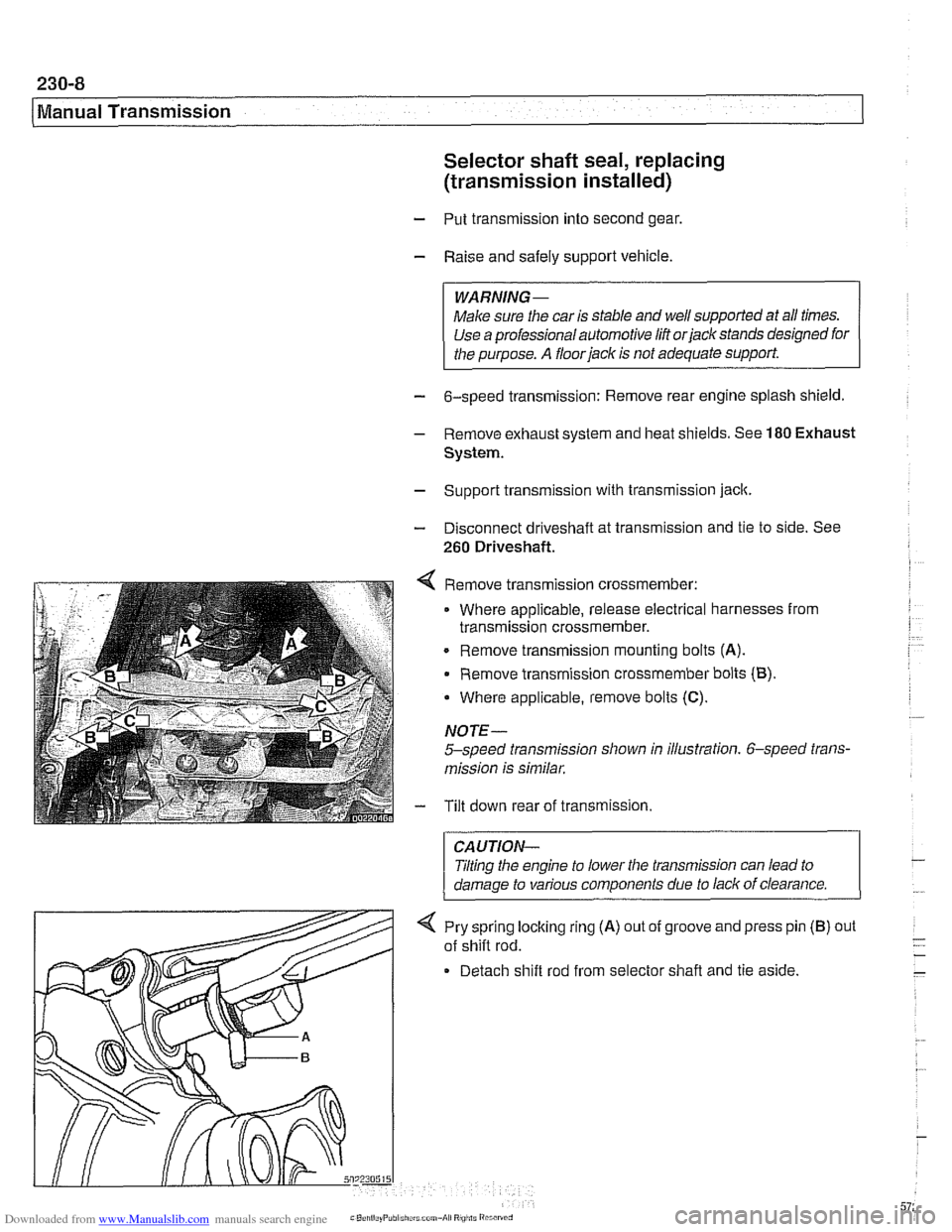
4 Remove transmission crossmember:
Where applicable, release electrical harnesses from
transmission crossmember.
. Remove transmission mounting bolts (A).
Remove transmission crossmember bolts (B).
Where applicable, remove bolts
(C).
NOTE-
5-speed transmission shown in illustration. 6-speed trans-
mission is similar.
- Tilt down rear of transmission.
CAUTION-
Jilting the engine to lower the transmission can lead to
damaae to various components due to lack of clearance.
-
4 Pry sprlng locking rlng (A) out of groove and press pin
of
sh~fl rod.
Detach
sh~ft rod from selector shafl and tie as~de.
(B) out
Page 586 of 1002
Downloaded from www.Manualslib.com manuals search engine
240-2
/ ~utomatic Transmission
This section covers maintenance and replacement of the
automatic transmission for
E39 models.
Automatic transmission internal repairs are not covered.
Such repairs require special service equipment and knowl-
edge. If it is determined that transmission internal
sewice is
required, consult an authorized BMW dealer about a factory
reconditioned unit or a transmission rebuild.
CAUTION-
ATF does not circulate unless the engine is running. When
towing an automatic transmission vehicle, use a flat bed truck
or raise the rear wheels off the ground.
Special tools
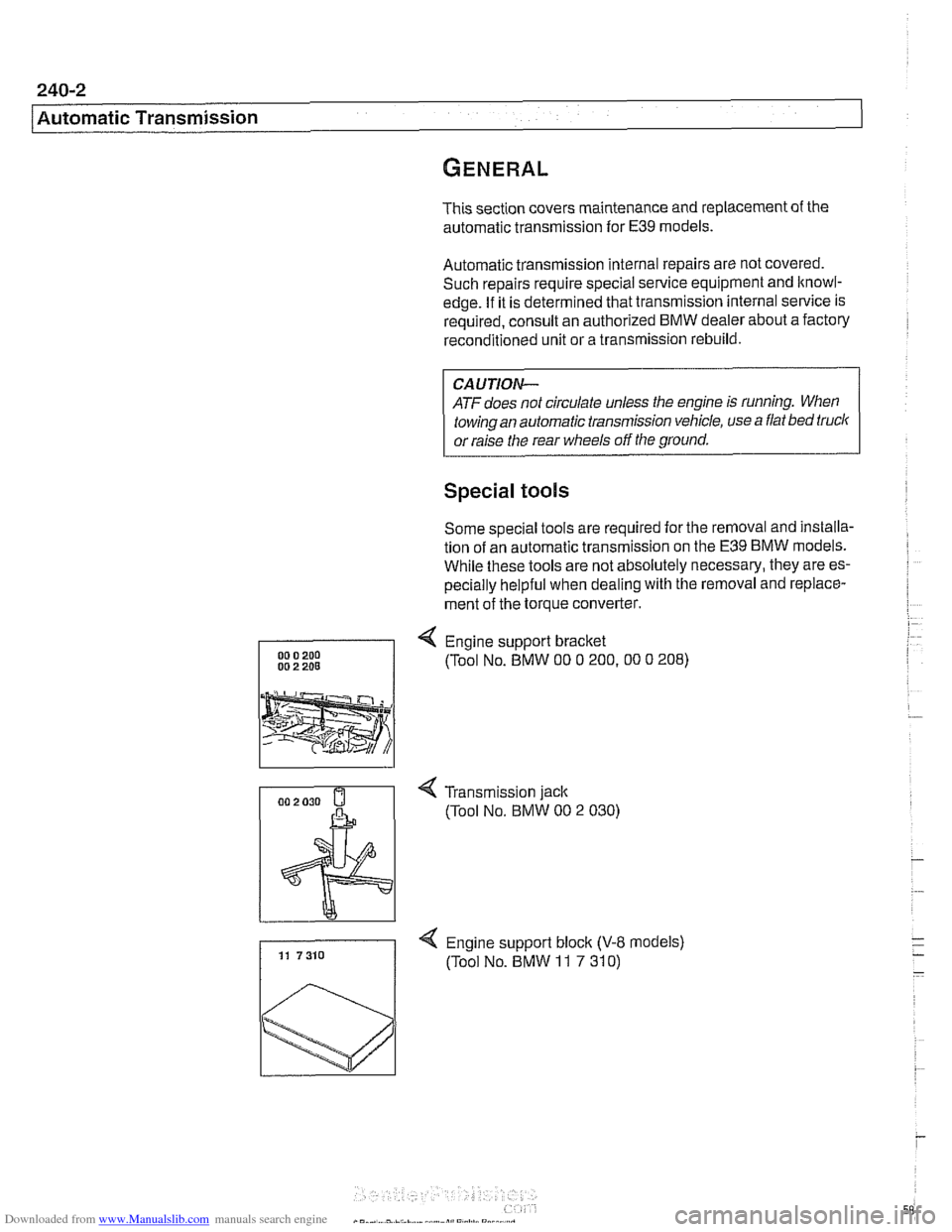
Some special tools are required for the removal and installa-
tion of an automatic transmission on the
E39 BMW models.
While these tools are not absolutely necessary, they are es-
pecially helpful when dealing with the removal and replace-
ment of the torque converter.
4 Engine support bracket
(Tool No. BMW
00 0 200.00 0 208)
4 Transmission jack
(Tool No.
BMW 00 2 030)
4 Engine support block (V-8 models) 11 7310 (Tool No. BMW 11 7 310)
Page 613 of 1002
Downloaded from www.Manualslib.com manuals search engine
Driveshaft, aligning
The alignment of the driveshaft does not normally need to be
checked unless the engineltransmission or the final drive
have been removed and installed. if ail other parts of the
driveshaft have been inspected and found to be okay, but
there is still noise or vibration, driveshaft alignment should be
checked.
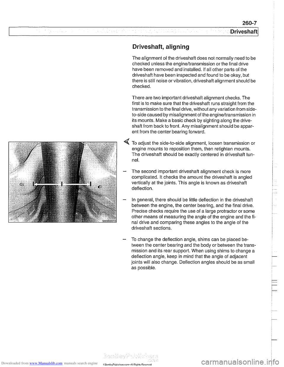
There are two important driveshaft alignment checks. The
first is to make sure that the driveshaft runs straight from the
transmission to the final drive, without any variation from
side-
to-side caused by misalignment of the engineltransmission in
its mounts. Make a basic check by sighting along the
drive-
shaft from back to front. Any misalignment should be appar-
ent from the center bearing forward.
To adjust the side-to-side alignment, loosen transmission or
engine mounts to reposition them, then retighten mounts.
The driveshaft should be exactly centered in driveshaft tun-
nel.
The second important driveshaft alignment check is more
complicated. It checlts the amount the driveshaft is angled
vertically at the joints. This angle is
lknown as driveshaft
deflection.
In general, there should be little deflection in the driveshaft
between the engine, the center bearing, and the final drive.
Precise checks require the use of a large protractor or some
other means of measuring the angle of the engine and the fi-
nal drive and comparing these angles to the angle of the
. . driveshaft sections.
- To change the deflection angle, shims can be placed be-
tween the center bearing and the body or between the trans-
mission and its rear support. When using shims to change a
deflection angle, keep in mind that the angle of adjacent
joints will also change. Deflection angles should be as small
as
oossible.
Page 616 of 1002
Downloaded from www.Manualslib.com manuals search engine
260-1 0
/ Driveshaft
Driveshaft, installing
- Prepare CV joint for reinstallation:
Extend joint to limit.
Clean off old grease and fill with fresh grease
Install new seal.
- Bend driveshaft slightly at center universal joint to install
CAUTION-
Do not allow CVjoint seal to become displaced.
- Align matchmarlts on driveshaft to matchmarks on final drive
and transmission flanges.
- Fit constant velocity joint to final drive input flange. Alternate-
ly tighten two opposite nuts to draw constant velocity joint
evenly into the final drive input flange. Once seated, tighten
down remaining nuts.
I CAUTION-
I Do not reuse self-locking nuts. These nuts are designed to be /
I used onlv once. 1
- Insert bolts in front of driveshafl to transmission output
flange. Counterhold each bolt while tightening nut.
CAUTION-
. Do not reuse self-locking nuts. These nuts are designed to
be used only once.
Avoid stressing the flex-disc when torquing the bolts.
Do this by counterholding the bolts and turning the nuts
on the flange side.
- Position center support bearing and install mounting nuts.
Use new self-locking nuts.
- Install heat shields.
- Install rear transmission support crossmember.
- Install exhaust system. See 180 Exhaust System.
Reconnect oxygen sensor wiring harnesses and reattach
wiring harness retainers to rear transmission support
crossrnernber.
Page 630 of 1002
Downloaded from www.Manualslib.com manuals search engine
300-1 0
/Suspension, Steering and Brakes - General
The steering system features variable power assist provided
by an engine-driven hydraulic pump.
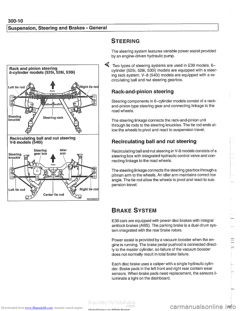
Rack and pinion steering
6-cylinder models
(525i, 5281, 5300
Two types of steering systems are used in E39 models. 6-
cylinder (525i, 5281, 530i) models are equipped with a steer-
ing rack system. V-8
(540i) models are equipped with a re-
circulating ball and nut steering gearbox.
Rack-and-pinion steering
Steering components in 6-cylinder models consist of a rack-
and-pinion type steering gear and connecting linltage to the
road wheels.
The steering linkage connects the rack-and-pinion unit
through tie rods to the steering knucltles. The tie rod ends al-
low the wheels to pivot and react to suspension travel.
Recirculating ball and nut steering
V-8 models
(540i)
I
Recirculating ball and nut steering
Recirculating ball and nut steering in V-8 models consists of a
steering box with integrated hydraulic control valve and con-
necting linkage to the road wheels.
Thesteering linkageconnects the steering gearbox through a
pitman arm to the wheels. An idler arm maintains correct toe
angle. The tie rod allow the wheels to pivot and react to sus-
pension travel.
E39 cars are equipped with power disc brakes with integral
antilock brakes (ABS). The parking bralte is a dual-drum sys-
tem integrated with the rear brake rotors.
Power assist is provided by a vacuum booster when the en-
gine is running. The brake pedal
pushrod is connected direct-
ly to the master cylinder, so failure of the vacuum booster
does not normally result in total
bralte failure.
Each disc bralte uses a caliper with a single hydraulic cylin-
der. Brake pads in the left front and right rear contain wear
sensors. When brake pads need replacement, the sensors il-
luminate a light on the dashboard.
Page 646 of 1002
Downloaded from www.Manualslib.com manuals search engine
31 0-1 0
Front Suspension
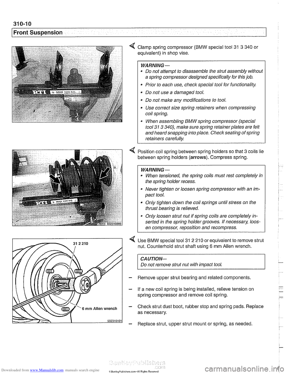
4 Clamp spring compressor (BMW special tool 31 3 340 or
equivalent) in shop vise.
WARNING-
* Do not attempt to disassemble the strut assembly without
a spring compressor designed specifically for this job.
Prior to each use,
checlc special tool for functionality.
Do not use a damaged tool.
Do not make any modifications to tool. Use correct size spring retainers when compressing
coil spring.
I When assembling BMW spring compressor (special
tool
31 3 340), make sure spring retainerplates are felt
and heard snapping into place. Check seating of spring
retainers carefully.
Position coil spring between spring holders so that
3 coils lie
between spring holders
(arrows). Compress spring.
WARNING -
When tensioned, the spring coils must rest completely in
the spring holder recess.
Never tighten or loosen spring compressor with an im-
pact tool.
Only tighten down the coil springs until stress on the
thrust bearing is relieved.
a Only loosen strut nut if spring coils are completely in-
serted in the spring holder grooves. If
necessarx loos-
en compressor, reposition and recompress.
Use
BMW special tool 31 2 21 0 or equivalent to remove strut
nut. Counterhold strut shaft using
6 mm Allen wrench.
CAUTION-
Do not remove strut nut with impact tool.
Remove upper strut bearing and related components.
If a new coil spring is being installed, relieve tension on
spring compressor and remove coil spring.
Check strut dust boot, rubber stop and spring pads. Replace
as necessary.
Replace strut, upper strut mount or spring, as needed
Page 664 of 1002
Downloaded from www.Manualslib.com manuals search engine
Steering and Wheel Alignment
Steering system warnings and cautions
WARNING -
The BMW airbag system is complex. Special precautions
must be observed when servicing the system. Serious in-
jury may result if system service is attempted by persons
unfamiliar with the BMW
airbag system and its approved
service procedures. BMW specifies that all inspection and
service should be
peiformed by an authorized BMW deal-
e,:
The BMW E39 is equipped with an airbag mounted in
the steering wheel. The
airbag is an explosive device
and should be treated with extreme caution. Always fol-
low the
airbag removal procedure as outlined in 721
Airbag System (SRS).
BMW airbags are equipped with a bacli-up power sup-
ply inside the
airbag control module. A 5 second wait-
ing period should be observed after the battery cable
has been disconnected. This will allow the reserve
power supply to discharge.
Do not reuse self-locking nuts. They are designed to
be used only once and may fail if reused. Always re-
place them with new locliing nuts.
* Do not install bolts and nuts coated with undercoating
wax, as correct tightening torque cannot be assured.
Always clean the threads with solvent before installa-
tion, or install new parts.
Do not attempt to weld or straighten any steering com-
ponents. Always replace damagedparts.
CAUTION--
- Some E39 models are equipped with aluminum suspen.
sion components. The following cautions apply:
Due to the chemical and corrosion characteristics of
aluminum, do not bring into contact with battery acid.
Do not clean with wire brushes with brass or iron bris-
tles. Only use brushes with stainless steel bristles.
Do
not expose to flying sparks from grindinghutting op-
erations.
Do not subject to steel welding splashes.
* Do not expose to temperatures over 80% (176°F).
even for short periods. Temperatures in painting iacili-
ties are not a problem.