rear BMW 525i 1997 E39 Workshop Manual
[x] Cancel search | Manufacturer: BMW, Model Year: 1997, Model line: 525i, Model: BMW 525i 1997 E39Pages: 1002
Page 843 of 1002

Downloaded from www.Manualslib.com manuals search engine
Trunk Lid, ~ail~atel
4 Loosen lower tailgate lock fasteners (arrows) so that tailgate
lock can center itself.
CAUTION-
The lower section of tailgate lock must not scrape against
the upper section.
The eccentric pin on the lower section of the tailgate
loclc rotates
when being locked from upper section of
tailgate lock.
- Disconnect tailgate latch actuator motor by squeeze locking
tabs on electrical harness connector and disconnecting.
CAUTION-
Eccentric pin in lower section of trunk lid lock must be at
lower dead center.
After disconnecting plug connector from actuator mo-
tor, tailgate is opened by electric
unloclcing fixture of up-
per section of tailgate loclc.
. For this reason, the cable connections to the upper
section of the tailgate loclc must remain connected.
Othe~tise the tailgate can only be opened by the emer-
gency handle. Eccentric pin of lower section of tailgate
loclc remains at bottom dead center point after unlock-
ing.
Tailgate alignment, height adjustment
4 Loosen left and right tailgate hinge fasteners (arrows) to al-
low tailgate to be adjusted.
CAUTION-
. When the hinge screws for the tailgate are released, the
position of the overall assembly changes with respect to
the body.
The position of the rear window frame to the tailgate re-
mains unchanged.
- Close tailgate carefully and check gap dimensions. See Tail-
gate alignment specifications below.
- Tighten hinge screws when gap dimensions are correct.
Page 845 of 1002
![BMW 525i 1997 E39 Workshop Manual Downloaded from www.Manualslib.com manuals search engine
. -
Trunk Lid, ~ail~ate]
< Adjustment D:
a = 4.5 rnrn + ll- 0.5 rnrn (0.18 in + 0.041- 0.02 in)
b = 3.7 rnrn +2 l- 1 rnrn (0.1 5 in + 0](/img/1/2822/w960_2822-844.png "BMW 525i 1997 E39 Workshop Manual Downloaded from www.Manualslib.com manuals search engine
. -
Trunk Lid, ~ail~ate]
< Adjustment D:
a = 4.5 rnrn + ll- 0.5 rnrn (0.18 in + 0.041- 0.02 in)
b = 3.7 rnrn +2 l- 1 rnrn (0.1 5 in + 0")
Downloaded from www.Manualslib.com manuals search engine
. -
Trunk Lid, ~ail~ate]
< Adjustment D:
a = 4.5 rnrn + ll- 0.5 rnrn (0.18 in + 0.041- 0.02 in)
b = 3.7 rnrn +2 l- 1 rnrn (0.1 5 in + 0.081 - 0.04 in)
4 Adjustment E:
1 tailgate lid
a=1.3rnrnil rnrn(0.05ini0.04in)
2 rear side panel
b = 4.5 rnrn + 11 - 0.5 rnrn (0.1 8 in + 0.041 - 0.02 in)
4 Adjustment F:
a = 1.3 rnrn 21 rnrn (0.05 in 20.04 in)
b = 1 rnrn 20.5 rnrn (0.04 i0.02 in)
* c=1.3rnrn+lrnrn/-1.3rnrn(0.05in+0.04in-0.05in)
d = 4.5 rnrn + 1 rnrn I - 0.5 rnrn (0.18 in + 0.041 - 0.02 in)
CAUTION-
Rear window frame must not extend above height of roof.
Olherwise, wind noise will be created.
Page 846 of 1002
Downloaded from www.Manualslib.com manuals search engine
41 2-1 8
Trunk Lid, Tailgate
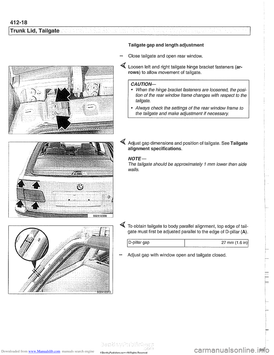
Tailgate gap and length adjustment
- Close tailgate and open rear window.
Loosen left and right tailgate hinge
bracket fasteners (ar-
rows)
to allow movement of tailgate.
CAUTION-
When the hinge bracket fasteners are loosened, the posi-
tion of the rear window frame changes with respect to the
tailgate.
Always
check the settings of the rear window frame to
the tailgate and
make adjustment if necessary
NOTE-
The tailgate should be approximately I mm lower then side
walls.
4 To obtain tailgate to body parallel alignment, top edge of tail-
gate must first be adjusted parallel to the edge
of D-pillar (A).
I D-pillar gap 27 rnrn (1.6 in)/
- Adjust gap with window open and tailgate closed.
Page 849 of 1002
Downloaded from www.Manualslib.com manuals search engine
41 2-21
Trunk Lid, ~ailaatel
Rear window, adjusting
NOTE- Three versions of rear window are used on
Sport Wagon
models.
Tailgate must be correctly adjusted before rear window ad-
justments are made.
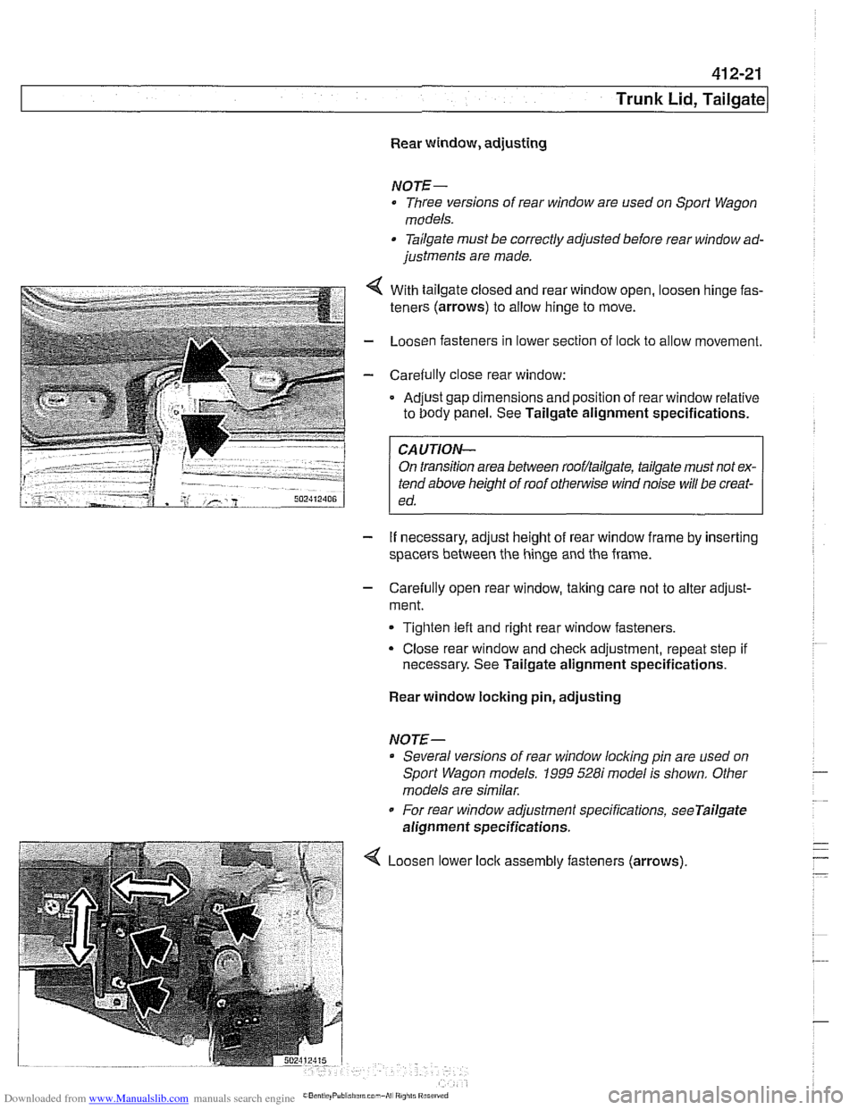
- . . . . . .. .. 4 With tailgate closeo ano rear window open, oosen ninge fas-
teners (arrows) to allow ninge to move.
- LoosL'n fasteners n lower section of ock to al ow movement.
- Care& ly c ose rear window:
Ad.~st gap dmensions and poston of rear window relative
to Oody panel. See Tailgate alignment specifications. .
FA-UTION- I
On transition area between rooflailgate, tailgate must not ex-
tend above height of roof
othe~lise wind noise will be creat-
ed.
- If necessary, adjust height of rear window frame by inserting
spacers between the hinge and the frame.
- Carefully open rear window, taking care not to alter adjust-
ment.
Tighten left and right rear window fasteners.
Close rear window and check adjustment, repeat step if
necessary. See Tailgate alignment specifications.
Rear window locking pin, adjusting
NOTE-- Several versions of rear window
locldng pin are used on
Sport Wagon models.
1999 528i model is shown. Other
models are similar.
For rear window adjustment specifications,
seeTailgate
alignment specifications.
Loosen lower assembly fasteners (arrows)
Page 850 of 1002
Downloaded from www.Manualslib.com manuals search engine
41 2-22
1 Trunk Lid, Tailgate
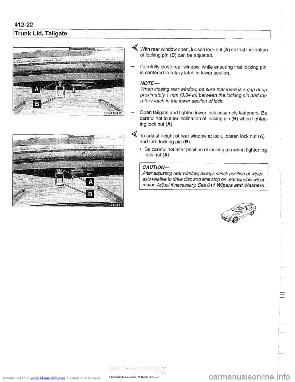
4 With rear window open, loosen loclc nut (A) so that inclination
of loclting pin
(B) can be adjusted.
- Carefully close rear window, while ensuring that locking pin
is centered in rotary latch in lower section.
NOTE-
When closing rear window, be sure that there is a gap of ap-
proximately
1 mm (0.04 in) between the locliing pin and the
rotary latch in the lower section of lock.
- Open tailgate and tighten lower loclc assembly fasteners. Be
careful not to alter inclination of loclting pin
(B) when tighten-
ing loclc nut
(A).
4 To adjust height of rear window at lock, loosen loclc nut (A)
and turn locking pin (B).
Be careful not alter position of loclting pin when tightening
lock nut
(A).
CA UTIOG
After adjusting rear window, always checlr position of wiper
axis relative to drive disc and limit stop on rear window wiper
motor. Adjust if necessary See 611 Wipers and Washers.
Page 851 of 1002
Downloaded from www.Manualslib.com manuals search engine
51 0 Exterior Trim. Bumpers
General ........................... .51 0.2 Exterior Trim ...................... 51 0-1 3
Outside Rear View Mirrors
Outside mirror glass. replacing
Outside mirror housing.
removing and installing
......
Outside mirror assemblv .
BMW emblem. removing and installing ... 510-13 .......... .51 0.2
Body side molding. replacing ........... 51 0-13 .......... .51 0.2
Radiator grill. removing and installing .... 51 0-1 4
Headlight housing trim panel.
.......... .51 0.3
removing and installing ............... 510-14 . .
removing and installing ................ .51 0.4
Bumpers ......................... .51 0.5
Front bumper assembly
............... .51 0.6
Front bumper, removing and installing
.... .51 0.7
Front bumper impact absorber. replacing
. .51 0.8
Rear bumper assembly ............... .51 0.9
Rear bumper. removing and installing
... .51 0.10
Rear bumper impact absorber. replacing
. .51 0.1 1
Front bumper height. adjusting
......... .51 0.12
Page 852 of 1002
Downloaded from www.Manualslib.com manuals search engine
-
Exterior Trim, Bumpers
This repair group includes repair information for the outside
rearview mirrors, front and rear bumpers, and the easily re-
movable exterior trim parts.
Many of the mirror components are separately available from
an authorized
BMW dealer, including the glass and outside .
plastic housing.
The
E39 models offered two types of outside mirrors, stan-
dard mirrors or automatic dip mirrors.
Outside mirror glass, replacing
CAUTIOI\C
Mirrorshould be at or above room temperature before remov-
al.
Othe~lise, small plastic parfs or glass may break.
Outside mirror glass without automatic dip control,
replacing
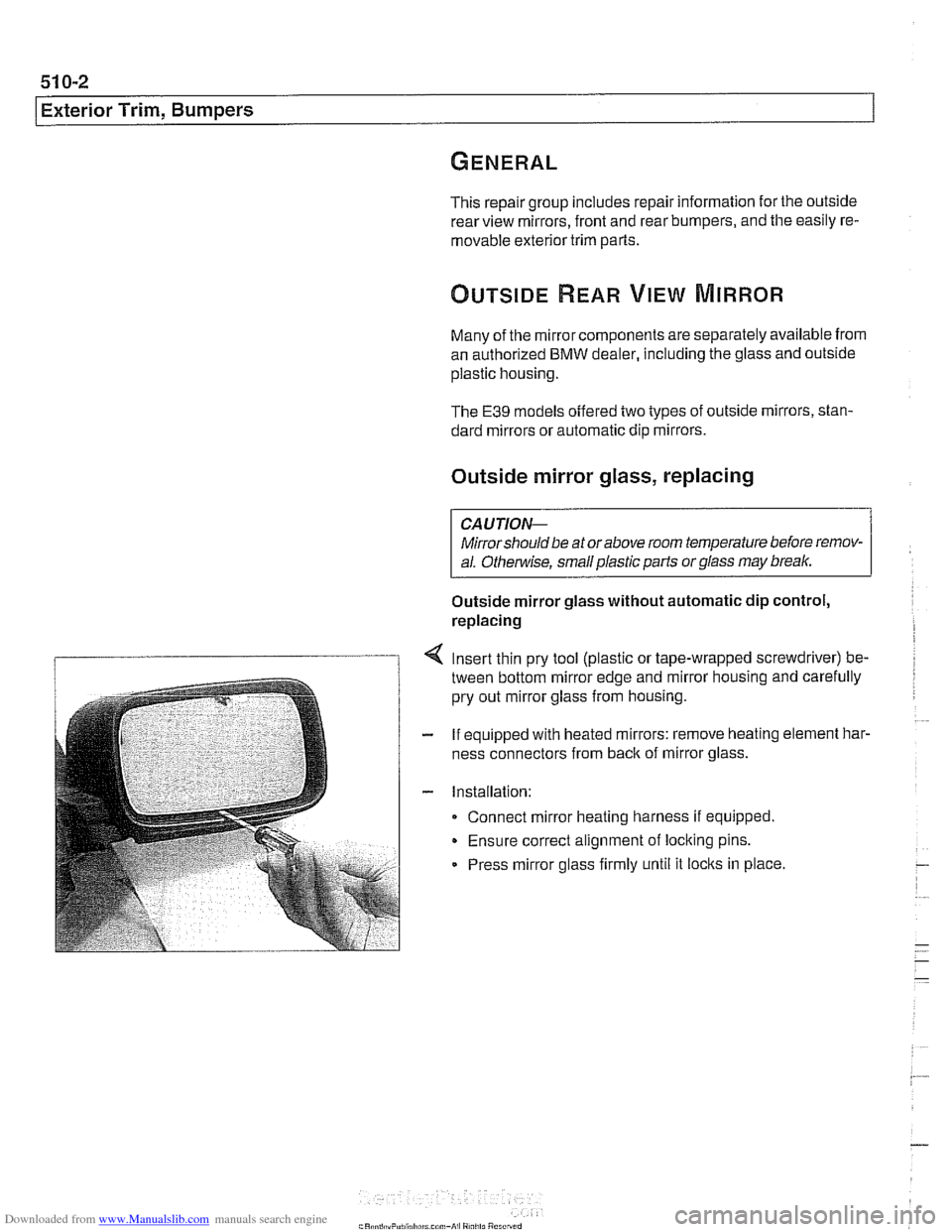
Insert thin pry tool (plastic or tape-wrapped screwdriver) be-
tween bottom mirror edge and mirror housing and carefully
pry out mirror glass from housing.
If equipped with heated mirrors: remove heating element
har.
ness connectors from back of mirror glass.
Installation: Connect mirror heating harness if equipped.
Ensure correct alignment of locking pins.
Press mirror glass firmly until it
locks in place.
Page 859 of 1002
Downloaded from www.Manualslib.com manuals search engine
51 0-9
Exterior Trim, J3umpers/
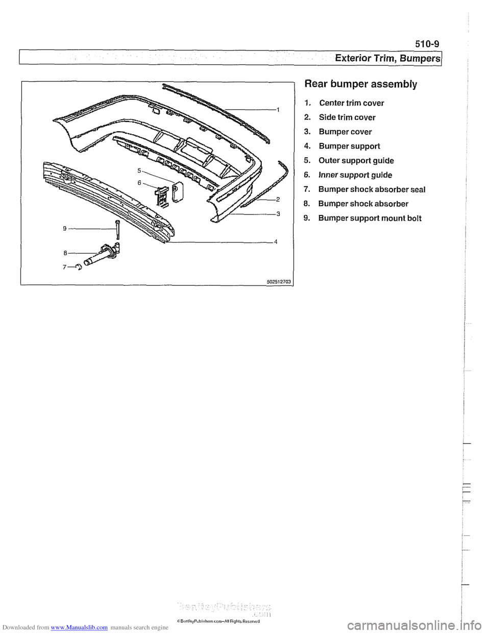
Rear bumper assembly
1. Center trim cover
2. Side trim cover
3. Bumper cover
4. Bumper support
5. Outer support guide
6. Inner support guide
7. Bumper shock absorber seal
8. Bumper shock absorber
9. Bumper support mount bolt
Page 860 of 1002
Downloaded from www.Manualslib.com manuals search engine
51 0-1 0
Exterior Trim, Bumpers Rear bumper, removing
and installing
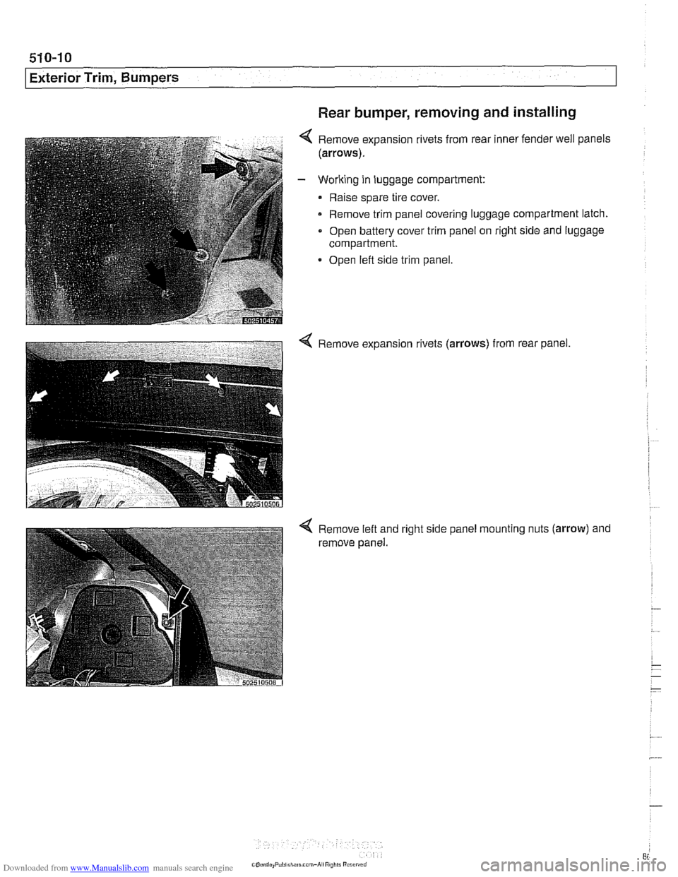
Remove expansion rivets from rear inner fender well panels
(arrows).
Working in luggage compartment:
Raise spare tire cover.
- Remove trim panel covering luggage compartment latch.
Open battery cover trim panel on right side and luggage
compartment.
Open left side trim panel.
4 Remove expansion rivets (arrows) from rear panel.
Remove left and
remove panel. right
side panel mounting
nuts (arrow) and
Page 861 of 1002
Downloaded from www.Manualslib.com manuals search engine
Exterior Trim, Bumpers
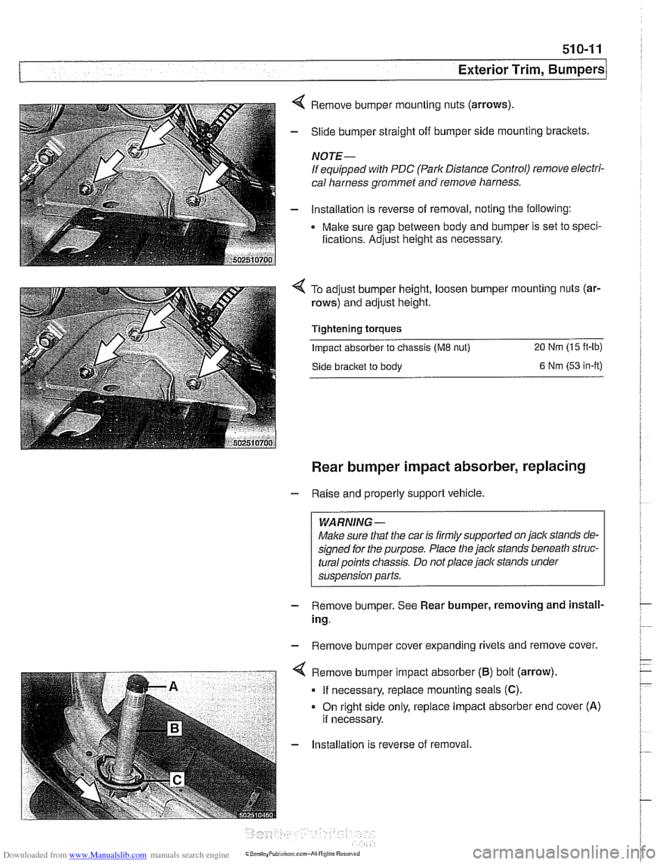
4 Remove bumper mounting nuts (arrows)
- Slide bumper straight off bumper side mounting brackets.
NOTE-
If equipped with PDC (Park Distance Control) remove electri-
cal harness grommet and remove harness.
- lnstallation is reverse of removal, noting the following:
Make sure gap between body and bumper is set to speci-
fications. Adjust height as necessary.
To adjust bumper height, loosen bumper mounting nuts (ar-
rows) and adjust height.
Tightening torques
Impact absorber to chassis (ME nut) 20 Nm (15 ft-lb)
Side bracket to body 6 Nm (53 in-it)
Rear bumper impact absorber, replacing
- Raise and properly support vehicle.
WARNING -
Make sure that the car is firmly supported on jack stands de-
signed for the purpose. Place the jack stands beneath
struc-
turalpoints chassis. Do not place jaclc stands under
suspension parts.
- Remove bumper. See Rear bumper, removing and install-
ing.
- Remove bumper cover expanding rivets and remove cover.
. - . . - . . ".-- < Remove b~mper mpact absorber (6) bot (arrow).
I If necessary, replace mounting seals (C).
- Installation is reverse of removal.