rear BMW 525i 1997 E39 Workshop Manual
[x] Cancel search | Manufacturer: BMW, Model Year: 1997, Model line: 525i, Model: BMW 525i 1997 E39Pages: 1002
Page 879 of 1002
Downloaded from www.Manualslib.com manuals search engine
513-1
51 3 lnterior Trim
General . . . . . . . . . . . . . . . . . . . . . . . . . . . ,513-2
Interior trim repairs . . . . . . . . . . . . . . . . . . . ,513-2
Center Console . . . . . . . . . . . . . . . . . . . . .513-3
Center console, removing and installing . . . 213-3
Dash Panel . . . . . . . . . . . . . . . . . . . . . . . . ,513-7
Lower dash panel assembly,
removing and installing
. . . . . . . . . . . . . . . . ,513-7
Upper dash assembly,
removing and installing
. . . . . . . . . . . . . . . ,513-1 1
Window and door post trim panels,
removing and installing
. . . . . . . . . . . . . . . 513-12
Dash panel support,
removing and installing
. . . . . . . . . . . . . . . 513-15
Rear parcel shelf panel,
removing and installing
. . . . . . . . . . . . . . . 513-15
Glove compartment,
removing and installing
. . . . . . . . . . . . . . . 513-16
Page 881 of 1002
Downloaded from www.Manualslib.com manuals search engine
513-3
Interior ~rirnl
The console between the two front seats starts behind the shifler housing. It houses the parking brake handle, optional
telephone and oddments storage tray. The rear portion of the
console houses the ashtray and covers the emergency brake
cable ends.
NOTE-
The accompanying photos illustrate a model with automatic
transmission. Manual transmission models are similar.
Center console, removing and installing
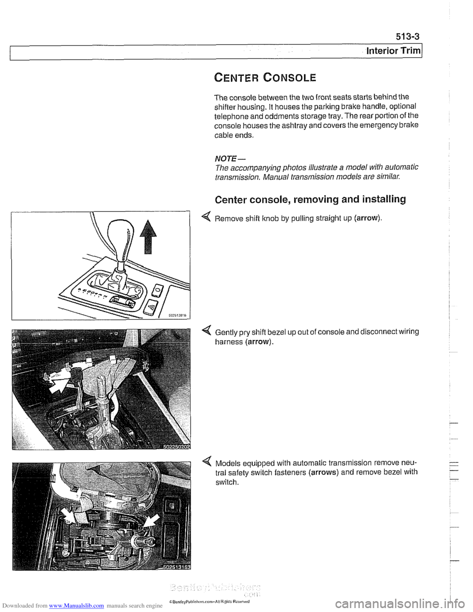
4 Remove shift knob by pulling straight up (arrow).
Gently pry shift bezel
harness (arrow). up
out of console and disconnect wiring
Models equipped with automatic transmission remove neu-
tral safety switch fasteners (arrows) and remove bezel with
switch.
Page 882 of 1002
Downloaded from www.Manualslib.com manuals search engine
51 3-4
/Interior Trim
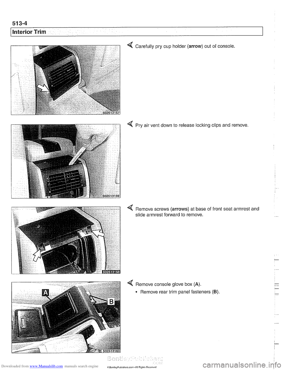
Carefully pry cup holder (arrow) out of console,
4 Pry air vent down to release locking clips and remove.
< Remove screws (arrows) at base of front seat armrest and
slide armrest forward to remove.
4 Remove console glove box (A).
Remove rear trim panel fasteners (B).
Page 883 of 1002
Downloaded from www.Manualslib.com manuals search engine
Interior iriml
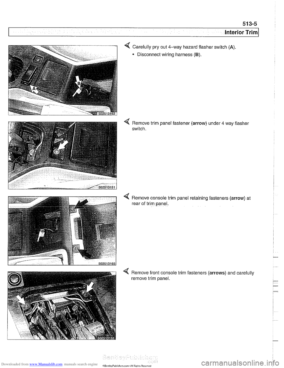
4 Carefully pry out 4-way hazard flasher switch (A)
Disconnect wiring harness (B).
Remove trim panel fastener (arrow) under 4 way flasher
switch.
4 Remove console trim panel retaining fasteners (arrow) at
rear of trim panel.
Remove front console trim fasteners
(arrows) and carefully
remove trim panel.
Page 884 of 1002
Downloaded from www.Manualslib.com manuals search engine
51 3-6
Interior Trim
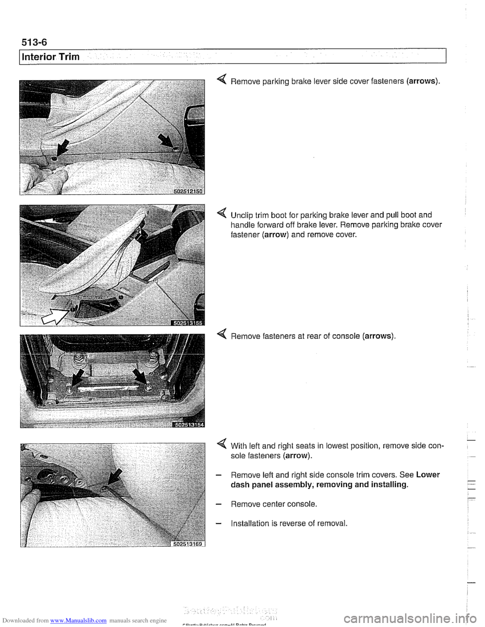
Remove parking bralte lever side cover fasteners (arrows)
4 Unclip trim boot for parking brake lever and pull boot and
handle forward off brake lever. Remove parking
bralte cover
fastener
(arrow) and remove cover.
4 Remove fasteners at rear of console (arrows).
4 With left and right seats in lowest position, remove side con-
sole fasteners
(arrow).
- Remove left and right side console trim covers. See Lower
- Remove center console.
- Installation is reverse of removal.
Page 891 of 1002
Downloaded from www.Manualslib.com manuals search engine
Interior ~riml
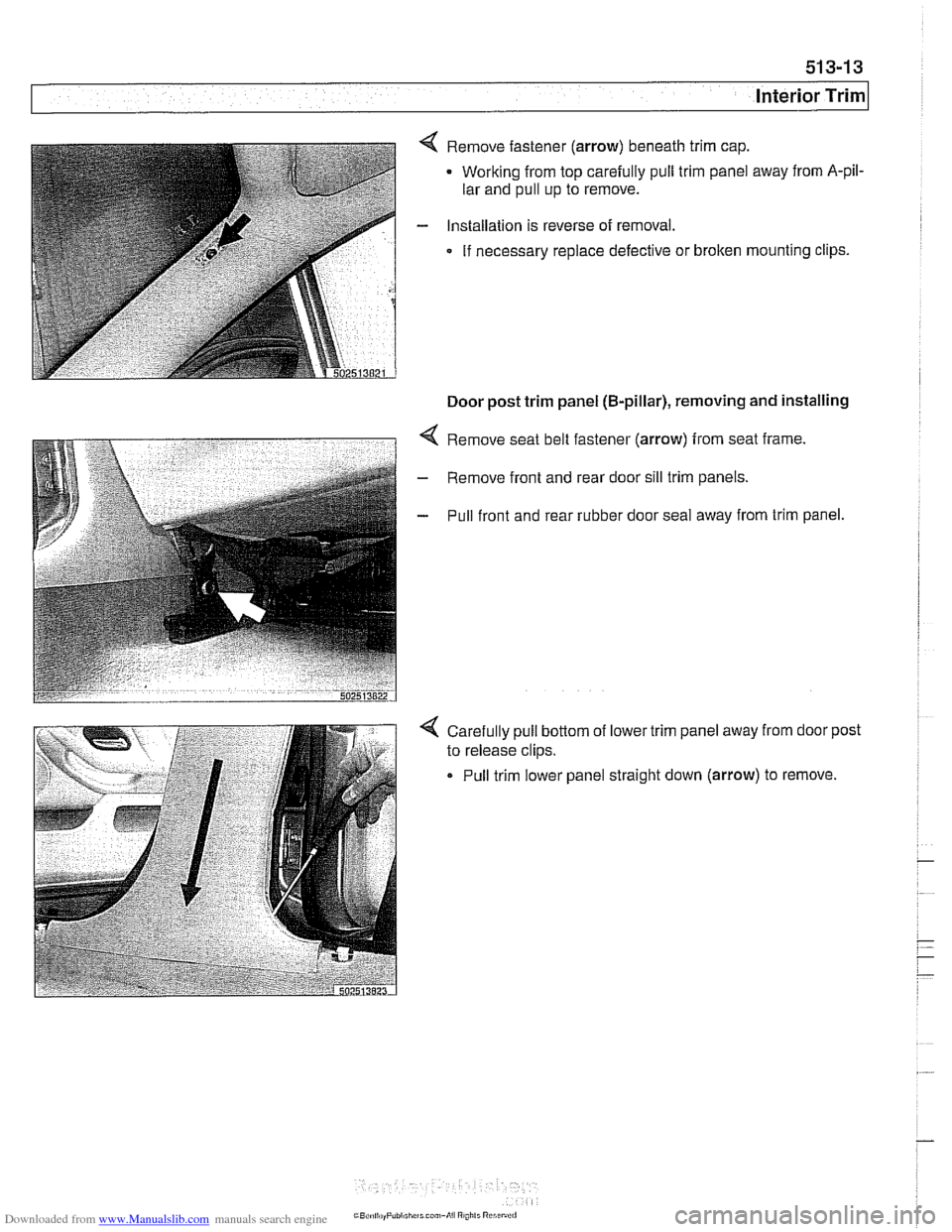
4 Remove fastener (arrow) beneath trim cap.
Working from top carefully pull trim panel away from
A-pil-
lar and pull up to remove.
- Installation is reverse of removal.
If necessary replace defective or broken mounting clips.
Door post trim panel (B-pillar), removing and installing
4 Remove seat belt fastener (arrow) from seat frame.
- Remove front and rear door sill trim panels.
- Pull front and rear rubber door seal away from trim panel.
4 Carefully pull bottom of lower trim panel away from door post
to release clips.
Pull trim lower panel straight down (arrow) to remove.
Page 892 of 1002
Downloaded from www.Manualslib.com manuals search engine
51 3-1 4
llnterior Trim
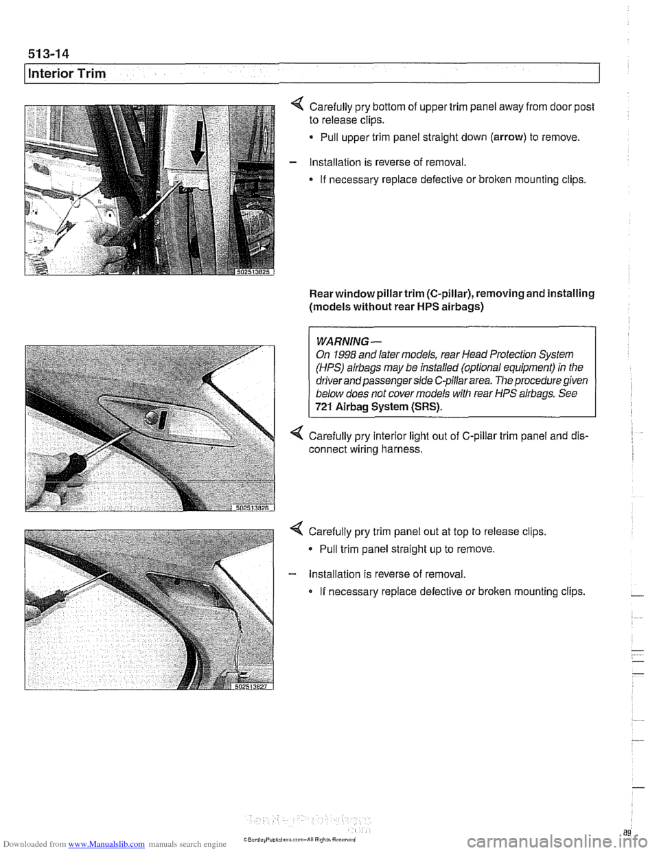
Carefully pry bottom of upper trim panel away from door post
to release clips.
Pull upper trim panel straight down (arrow) to remove.
Installation is reverse of removal.
If necessary replace defective or
broken mounting clips.
Rear window pillartrim (C-pillar), removing and installing
(models without rear
HPS airbags)
1 I
WARNING-
On 1998 and later models, rear Head Protection System
(HPS)
airbags may be installed (optional equipment) in the
driver and passenger side C-pillar area.
The procedure given
below does not cover models with rear HPS airbags. See
721 Airbag System (SRS).
4 Carefully pry interior light out of C-pillar trim panel and dis-
connect wiring harness.
Carefully pry trim panel out at top to release clips,
- Pull trim panel straight up to remove.
- lnstallation is reverse of removal.
If necessary replace defective or broken mounting clips.
Page 893 of 1002
Downloaded from www.Manualslib.com manuals search engine
51 3-1 5
I Interior Trim
Dash panel support, removing and
installing
- Remove lower dash panel. See Lower dash panel assem-
bly, removing and installing.
- Remove upper dash panel. See Upper dash assembly, re-
moving and installing.
- Remove upper steering column fasteners. See 320 Steering
and Wheel Alignment.
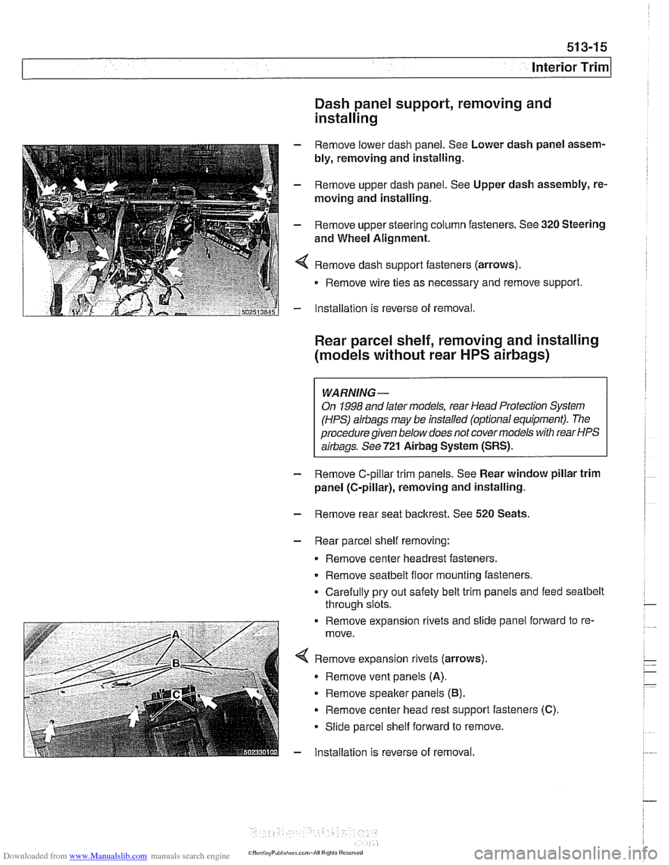
4 Remove dash support fasteners (arrows).
Remove wire ties as necessary and remove support.
- Installation is reverse of removal.
Rear parcel shelf, removing and installing
(models without rear
HPS airbags)
WARNING-
On 1998 and later models, rear Head Protection System
(HPS)
airbags may be installed (optional equipment). The
procedure given below does not covermodels with rear HPS
airbags. See721
Airbag System (SRS).
- Remove C-pillar trim panels. See Rear window pillar trim
panel (C-pillar), removing and installing.
- Remove rear seat backrest. See 520 Seats.
- Rear parcel shelf removing:
Remove center headrest fasteners.
Remove
seatbelt floor mounting fasteners.
Carefully pry out safety belt trim panels and feed
seatbelt
through slots.
. . . - -. . . . . . . . . Remove expansion rivets and slide pane fonvard to re-
move.
< Remove expanson r:vets (arrows).
Remove vent panels (A).
Remove speafter pane s (B).
Remove center head rest s-pporl fasteners (C).
Slioe parcel shelf forward lo remove.
- lnsta lation s reverse of removal.
Page 895 of 1002
Downloaded from www.Manualslib.com manuals search engine
51 5 Central Locking and Anti-Theft
........................... General .51 5.2
Central Locking ................... .51 5.2
General Module
..................... .51 5.2
Central locking inputs and outputs
....... .51 5.3
Doorlocks
........................... 515-5
Trunklock
........................... 515-7
Remote entry (FZV)
.................. .51 5.7
Remote entry (FZV) inputs and outputs ... .51 5.8
Car Memory I Key Memory ............ .51 5.12
Trunk lid soft close (SCA)
............. .51 5.13
SCA subsystem
.................... .51 5.14
........ Tailgate and rear window locks
.51 5.14
Sport Wagon tailgate and rear
window
lock schematic ............... .51 5.15
Door Handles and Locks .......... .51 5.16
Door handle (outer), removing
and installing
....................... .51 5.16
Door latch, removing and installing
..... .51 5.17
Outer door lock cylinder, removing
and installing
....................... .51 5.18
Trunk Lock Assembly ............. 515-1 9
Trunk lock. removing and installing
...... 515-19
Trunk lock striker plate. removing
and installing
....................... 515-20
Tailgate lock. emergency release
....... 515-21
... Electronic Immobilization (EWS) 515-21
EWS variations
..................... 515-22
......... EWS control module. replacing 515-23
Transmitter
1 receiver module .......... 515-23
....................... Ring antenna 515-23
Anti-theft System (DWA) ........... 51 5-24
DWA LED Status
.................... 51 5-24
Tilt sensor
......................... 515-24
Interior protection .................... 51 5-25
Glass breakage sensors
.............. 515-26
Emergency disarming
................ 51 5-26
Page 898 of 1002
Downloaded from www.Manualslib.com manuals search engine
51 5-4
I Central Locking and Anti-Theft
Driver's door lock
The
lock/unlock signals are sent as input to the door module
from two microswitches on the lockcylinder. The driver's door
module carries out the locking
/ unlocking functions of the
driver's door through its final stage control.
The signal to lock the remaining doors, trunk or tailgate and
fuel flap is sent over the P-Bus to the GM and the passenger
door module. Activation of the passengers door
loclt is carried
out by the passenger door module. The rear doors, trunlt or
tailgate and fuel flap are
locked by the f~nal stage in the GM.
When
locked from the outside, all doors are set to the double
lock position and the GM will not carry out any unlock com-
mands from the central
loclc button or remote trunk release
button.
Selective unlocking
When unlocking with the key or the remote transmitter, the
first unloclcrequestwill only unlock the driver'sdoor. A second
unlock request will unlock the remaining doors, trunk or tail-
gate and fuel flap.
Trunk locking
I
The vehicle can be locked/unlocked from the trunlc loclc cylin-
der. The GM locks the trunk or tailgate, rear doors and fuel fill-
er. The locking command is passed over the P-Bus to the
respective door modules to lock the driver's and passengers
doors.
Locking the trunk and removing the key in the
hor~zontal posi-
tion will set the valet lock and prevent opening of the trunlt
with the central locking system.
Central locking switch
-
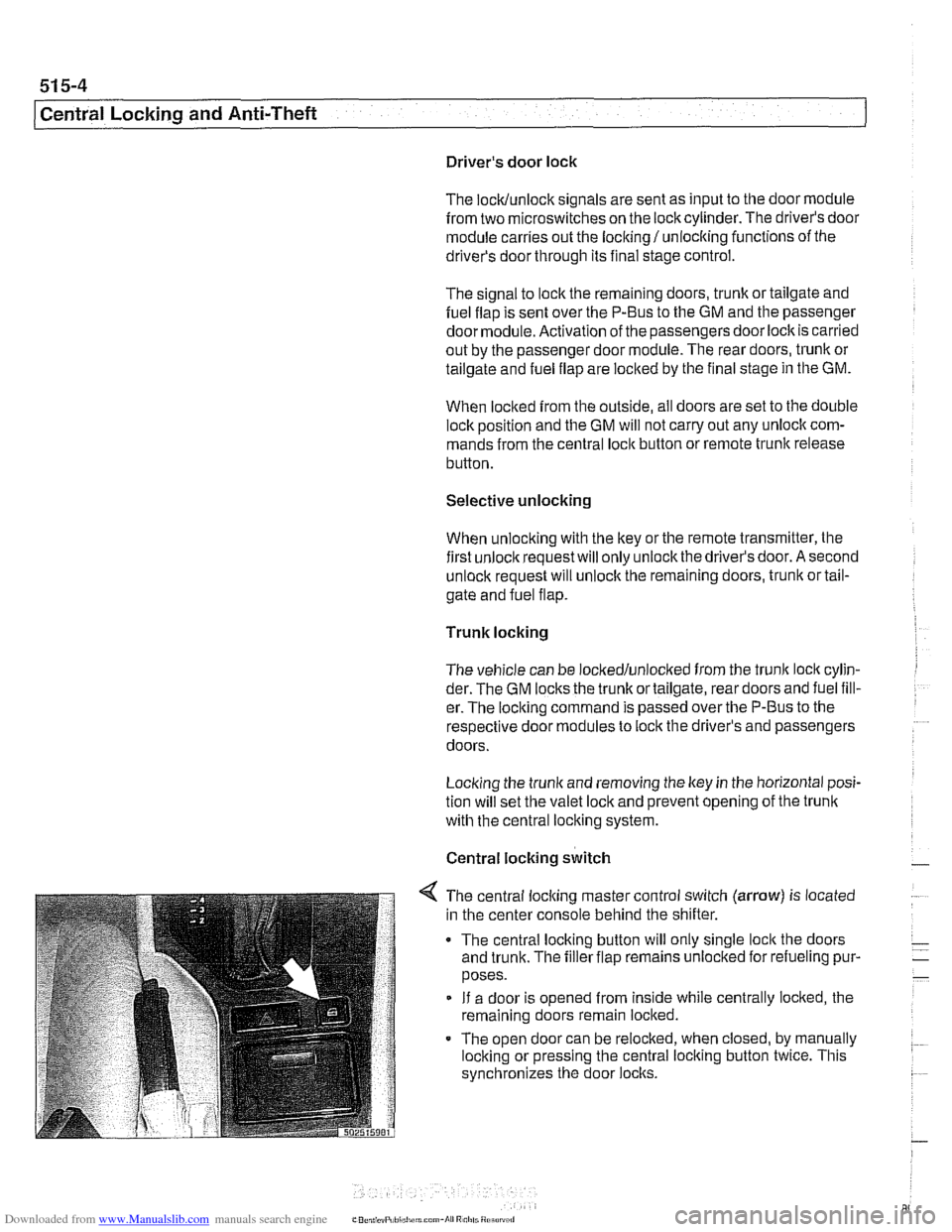
< The central locking master control switch (arrow) is located
in the center console behind the shifter.
The central locking button will only single
loclt the doors
and trunk. The filler flap remains unloclted for refueling pur-
poses.
If a door is opened from inside while centrally locked, the
remaining doors remain locked.
The open door can be relocked, when closed, by manually
locking or pressing the central locking button twice. This
synchronizes the door
locks.