rear BMW 525i 1997 E39 Workshop Manual
[x] Cancel search | Manufacturer: BMW, Model Year: 1997, Model line: 525i, Model: BMW 525i 1997 E39Pages: 1002
Page 946 of 1002
Downloaded from www.Manualslib.com manuals search engine
720-8
I Seat Belts
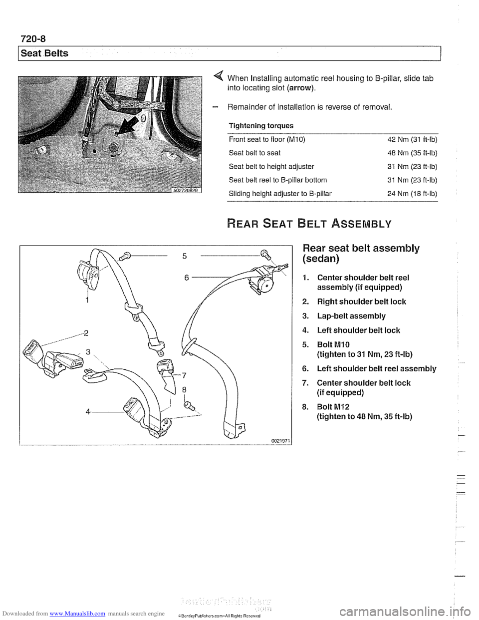
When Installing automatic reel housing to 5-pillar, slide tab
into locating slot (arrow).
Remainder of installation is reverse of removal
Tightening torques
- -.
Front seat to floor (M10) 42 Nm (31 ft-lb)
Seat belt to seat 48 Nm (35 ft-lb)
Seat belt to height adjuster 31 Nm
(23 it-lb)
Seat belt reel to €3-pillar bottom 31 Nm (23 ft-lb)
Sliding height adjuster to €3-pillar
24 Nm (18 ft-lb)
Rear seat belt assembly
(sedan)
1. Center shoulder belt reel
assembly
(if equipped)
2. Right shoulder belt lock
3. Lap-belt assembly
4. Left shoulder belt lock
5. Bolt MlO
(tighten to 31 Nm, 23 ft-lb)
6. Left shoulder belt reel assembly
7. Center shoulder belt lock
(if equipped)
8. Bolt M12
(tighten to 48 Nm, 35 ft-lb)
Page 947 of 1002
Downloaded from www.Manualslib.com manuals search engine
-- -
Seat Belts
Rear seat belts (sedan)
- Remove rear parcel shelf to access shoulder belt assembly
mounting bolts. See 513 Interior Trim.
- Remove rear seat cushion to access rear seat belt lock
mounting bolts. See 520 Seats.
- When installing seat belt lock straps:
Install right lock strap (which is shorter) underneath middle
lock strap.
Install left lock strap underneath middle lap belt strap.
Metal strap ends must rest against stop on floor under-
neath seat.
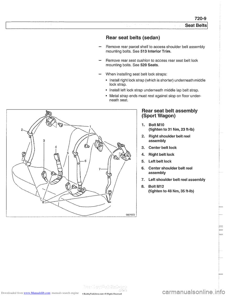
Rear seat belt assembly
(Sport Wagon)
1. BoltMlO
(tighten to 31 Nm, 23 ft-lb)
2. Right shoulder belt reel
assembly
3. Center belt lock
4. Right belt lock
5. Left belt lock
6. Center shoulder belt reel
assembly
7. Left shoulder belt reel assembly
8. Bolt
MI2
(tighten to 48 Nm, 35 ft-lb)
Page 948 of 1002
Downloaded from www.Manualslib.com manuals search engine
720-1 0
Seat Belts
Rear seat belts (Sport Wagon)
- Center shoulder belt:
Remove shoulder belt guide trim at top of seat backrest.
Feed belt out through slot in trim. Working in cargo com-
partment, partially remove backrest cover to access shoul-
der belt reel.
Remove shoulder belt reel mounting bolt inside backrest.
- Outboard shoulder belt:
Remove roof-pillar (C-pillar) trim.
Remove center shoulder belt.
- Lift up rear seat cushion(s) to access rear seat belt loclc
mounting
bolt(s).
- When installing seat belt loclc straps:
Install right belt loclc strap (which is shorter) underneath
center belt lock strap.
Install left belt loclc strap underneath center lap belt strap.
- Metal strap ends must rest against stop on floor underneath
seat.
Page 950 of 1002
Downloaded from www.Manualslib.com manuals search engine
721 -2
l~irba~ System (SRS)
This repair group covers airbag components and replace-
ment.
Airbag system repairand fault diagnosis is not covered.
Diagnostics, component testing, and
airbag system repair
should be carried out by trained BMW service technicians.
Individual
airbag system components can only be tested elec-
tronically when installed in the car. BMW service testers
DIS
or MoDiC or equivalent must be used for diagnostic work.
WARNING-
Special test equipment is required to retrieve airbag fault
codes, diagnose system faults, and
reseffturn off the air-
bag indicator light. The indicator light will remain on until
any problem has been corrected and the fault memory has
been cleared.
Airbags are part of the BMW Multiple Restraint System
(MRS). Three versions of MRS are available in E39 models.
Multiple Restraint Systems
MRS and MRS II include the following restraint components:
311 996-811 997
911
997-311 999
311 999-2002
Driver and passenger front
airbags (MRSIMRS II)
MRS
MRS
II
MRS Ill
Passenger front two-stage airbag (cars manufactured
from
911998).
The seat occupancy sensor (SBE) is used for detection of
a passenger in the right front seat. MRS uses the SBE in-
put to determine seat belt tensioner
and/or front airbag de-
ployment thresholds.
Side impact
airbag for driver and front passenger
(MRSIMRS II)
Leftlright side impact crash sensors (MRSIMRS 11)
Side impact airbag for rear passenger (MRS II) (optional)
Head Protection System (HPS) for driver and front passen-
ger (MRS
II)
Battery Safety Terminal - BST (MRS II)
Hall Sensor seat belt switches (MRS II)
Front pyrotechnic seat belt tensioners
Fuel pump cut off message
Page 951 of 1002
Downloaded from www.Manualslib.com manuals search engine
721 -3
Airbag System (SRS)
MRS Ill adds the following features:
MRS
Ill employs "smart" technology. Smart technology re-
fers to the control module's programming for the deploy-
ment of the airbags, in stages depending on the severity of
the impact.
Two-stage a~rbag for ooln drver and passenger Alloivs for
a softer
c~snioning elfecl when the airbags are lr ggered at
lighter impact,
MRS
Ill satellite sensors use 2 wire connectors
Rear side
airbags arrive de-activated from the factory and
can only be activated upon written request from the cus-
tomer.
Rear seat head protection is available when ordered with
optional rear seat side airbags.
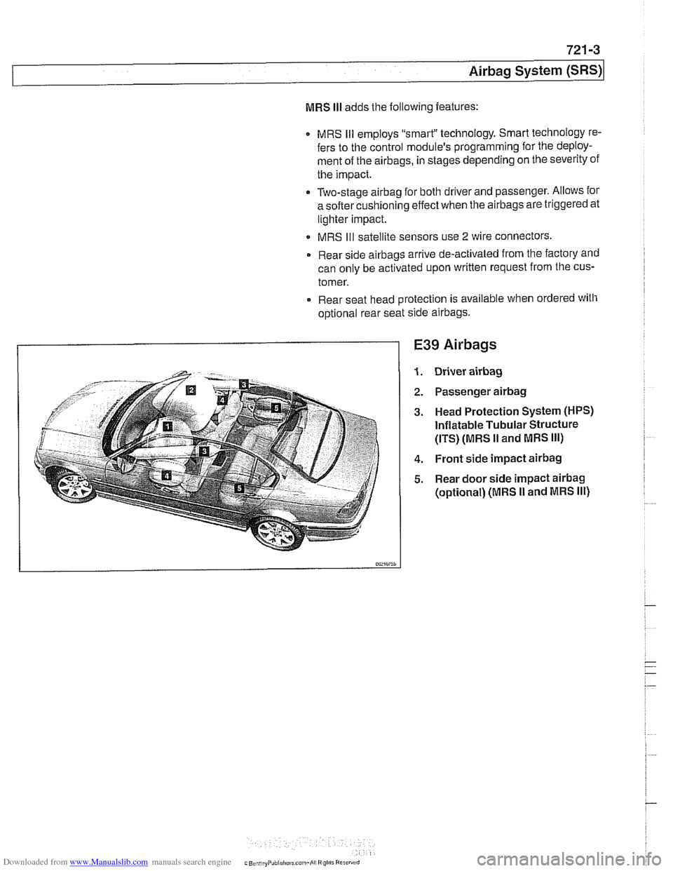
E39 Airbags
Driver airbag
Passenger airbag
Head Protection System (HPS)
Inflatable Tubular Structure
(ITS) (MRS
II and MRS Ill)
Front side impact airbag
Rear door side impact airbag
(optional) (MRS I1 and MRS Ill)
Page 955 of 1002
Downloaded from www.Manualslib.com manuals search engine
Airbag System (SRS)~
MRS control module, replacing
- Disconnect negative (-) cable from battery and cover nega-
tive terminal with insulating material.
CAUTIOI\C
Prior to disconnecting the battery, read the battery discon-
nection cautionsgiven in001 General Warnings and
Cau-
tions.
- Remove center console between front seats. See 513 lnteri-
or Trim.
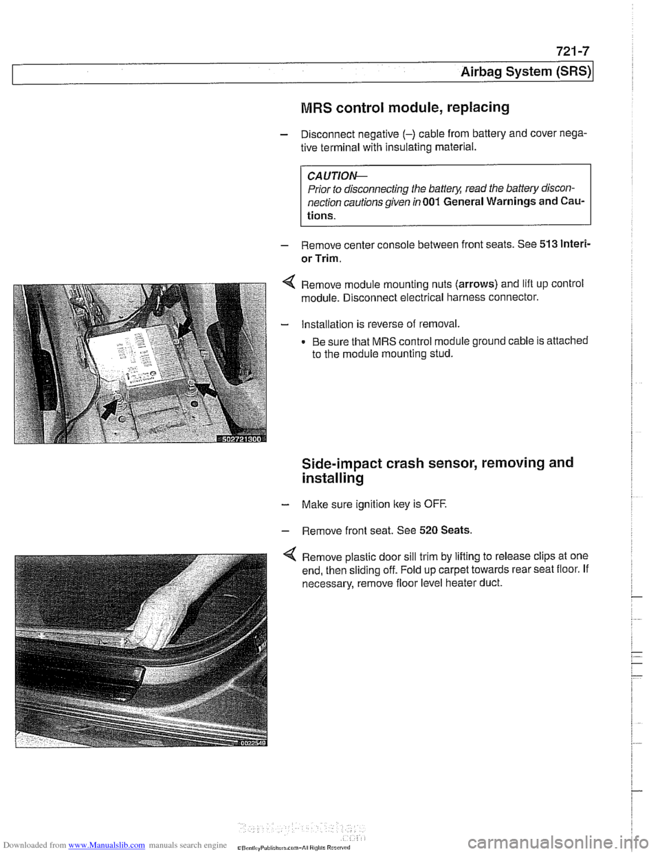
Remove module mounting nuts (arrows) and lift up control
module. Disconnect electrical harness connector.
Installation is reverse of removal.
Be sure that MRS control module ground cable is attached
to the module mounting stud.
Side-impact crash sensor, removing and
installing
- Make sure ignition key is OFF.
- Remove front seat. See 520 Seats.
Remove plastic door sill trim by lifting to release clips at one
end, then sliding off. Fold up carpet towards rear seat floor. If
necessary, remove floor level heater duct.
Page 957 of 1002
Downloaded from www.Manualslib.com manuals search engine
721 -9
Airbaq System ~SRS)~
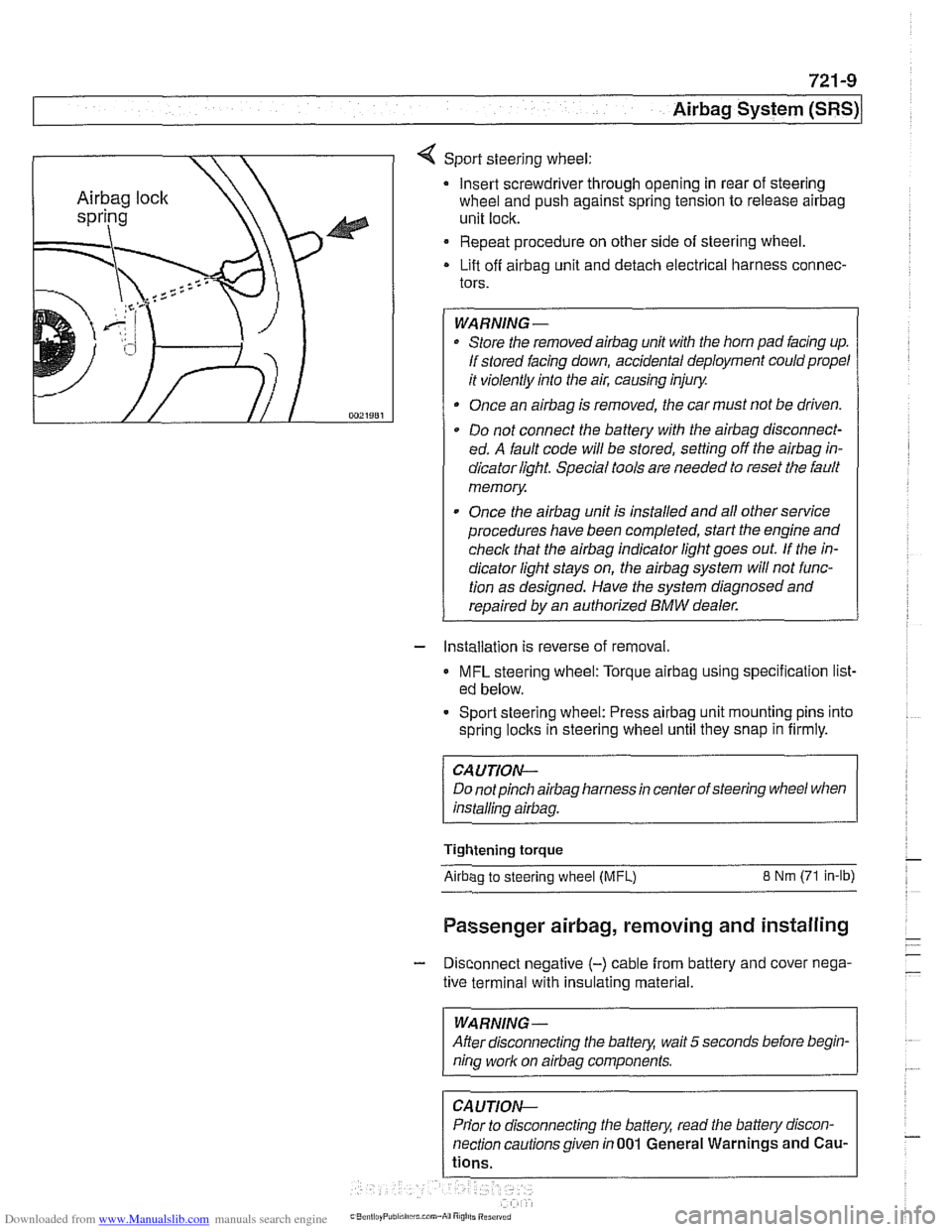
4 Sport steering wheel:
Insert screwdriver through opening in rear of steering
wheel and push against spring tension to release
airbag
unit lock.
Repeat procedure on other side of steering wheel.
Lift off
airbag unit and detach electrical harness connec-
tors.
WARNING-
Store the removedairbag unit with the horn pad facing up.
If stored facing down, accidental deployment could propel
it violently into the air, causing injury.
Once an
airbag is removed, the car must not be driven.
Do not connect the battery with the
airbag disconnect-
ed. A fault code will be stored, setting off the
airbag in-
dicator light Special tools are needed to reset the fault
memory
Once the
airbag unit is installed and all other service
procedures have been completed, start the engine and
check that the
airbag indicator light goes out. If the in-
dicator light stays on, the
airbag system will not func-
tion as designed. Have the system diagnosed and
repaired by an authorized
BMW dealer.
- Installation is reverse of removal.
MFL steering wheel: Torque airbag using specification list-
ed below.
- Sport steering wheel: Press airbag unit mounting pins into
spring
loclts in steering wheel until they snap in firmly.
CAUTION--
Do notpinch airbag harness in center of steering wheel when
installino
airbaa.
Tightening torque
Airbao to steerino wheel IMFL) 8 Nm (71 in-lb)
Passenger airbag, removing and installing
- Disconnect negative (-) cable from battery and cover nega-
tive terminal with insulating material.
--
WARNING -
After disconnecting the batteg wait 5 seconds before begin-
nina work on airbaa components.
Prior to disconnecting the battery, read the battery discon-
nection cautionsgiven in001 General Warnings and
Cau-
Page 959 of 1002
Downloaded from www.Manualslib.com manuals search engine
721 -1 1
Airbag System (SRS)~
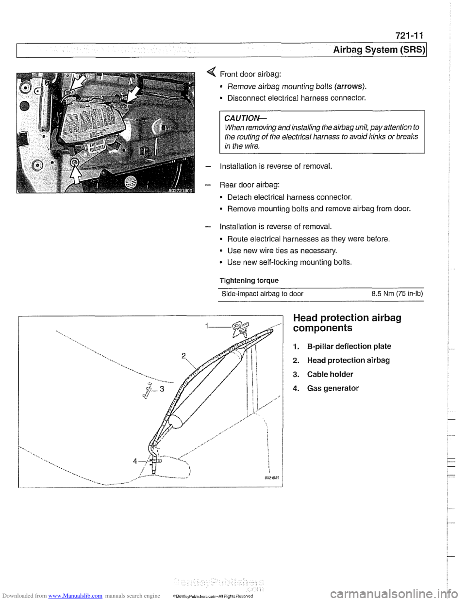
Front door airbag:
Remove airbag mounting bolts (arrows).
Disconnect electrical harness connector.
CAUTIOI\C
When removing andinstalling the airbag unit, pay attention to
the routing
of the electrical harness to avoid kinks or breaks
in the wire.
Installation is reverse of removal,
Rear door
airbag:
Detach electrical harness connector.
Remove mounting bolts and remove
airbag from door.
- Installation is reverse of removal.
Route electrical harnesses as they were before.
Use new wire ties as necessary.
Use new self-locking mounting bolts.
Tightening
torque
Side-impact airbag to door 8.5 Nm (75 in-lb)
Head protection airbag
components
1. B-pillar deflection plate
2. Head protection airbag
3. Cable holder
4. Gas generator
Page 992 of 1002
Downloaded from www.Manualslib.com manuals search engine
2 INDEX
Battery, starter, alternator
alternator (generator)
121-10
6-cylinder engine, removingi
installing 121-15
M62 engine 121-16
M62 TU engine (water cooled)
121-18
battery
121-5 charging 121-9
safety terminal 121-3
testing 121-5 charging system, troubleshooting
121-12
starter
121-1 9
6-cylinder engine, removingi instaliinq 121-20 . V-8 engine, rernovinglinsialiing
121-21
solenoid, removinglinstalling
121-23 troubleshooting 121-19
see also Maintenance
Bearing, wheel
see Front suspension
see also Rear suspension
Belts see Maintenance, drive belts
Blade, wiper
see Wipers and Washers
Blower motor see
A/C
BMW emblem
see Exterior trim
BMW special tools 010-18 see also special tools section at
beginning
of each repair group
Body dimensions 400-2
interior features
400-9 salety and security 400-7
Body side molding
see Exterior trim
Bonnet see Engine hood
Boot see Trunk
Brake fluid
020-24, 340-8
Brake fluid pressure sensor
340-30
Brakes
ABS, ASC or DSC system
300-12
component replacement 340-26
ASCIDSC switch
see Switches
bleeding
bralces 340-8
brake booster 340-1 9 bralce Dads. caiioers and rotors ,., 340-1 1
descriotion 300-10
e~ectrdnic brake & stability 300-11
light switch
see Switches
master cylinder
340-16 pariking brake 340-22
troubleshooting 340-5
Bulbs see Lights
Bumper
lront 510-6 height, adjusting 510-12
rear 510-9
Bus system
600-4
Camber
320-33
Camshaft
removingiinslaiiing
M52 engine 116-12
M52 TU
/ M54 engine 116-1 9 M62 engine 11 6-39
wear
116-6
Camshaft position sensors
see ignition system
Camshaft timing chain
adjusting M52 engine
117-22
M52 TU I M54 engine 117-43
M62 engine 117-79 removinglinstalling
M52 engine 117-26
M52TU 1 M54 engine 113-46.116-
28
M62 engine 117-66
Capacities, fluid
020.10
Car rnemorvlicev memorv . . 600-10
see also Centrai
lociking
Carbon canister, activated
see Fuel
tank
Caster
320-33
Catalytic converter and oxygen sensor 020-19
see also Exhaust system: exhaust
manilolds
Cautions
001-3
CD changer
650-4
Center bearing, driveshaft
see Driveshait
Center brake light
sedan
630-13
Center console
513-3
Centrai body electronics (ZKE 111)
600-6
Central locking
car memoryiey memory 515.12 general module iunctions 515-2
remote entry (FZV) 515-8
remote lkey initialization 515-10 single lociddouble ioclk 515-6
switch 515-4
Chain
see Camshaft liming chain
Characteristic map (electrically heated) thermostat
see Electrically heated thermostat
Charging system
see Battery, starter, alternator
Cluster see instruments
Clutch fluid see Maintenance
hydraulics
210-4
mechanical 210-9
switch
see Switches, pedal ciuster
variations
210.10
Codes, fault OED-1
Coil
see Ignition system
Coil spring
see Front suspension
see also Rear
suspe nsion
Page 993 of 1002
Downloaded from www.Manualslib.com manuals search engine
WARNING
Your common sense, good
judgement, and general alertness are
crucial lo sale and
successlul service
work. Belore attempling any work on
your BMW, be sure to read 001
General Warnings and Cautions
and lhe copyright page
a1 llle Iron1 01
the manual. Review lliese warnings
and cautions each time you prepare
lo work on your
BMW Please also
read any warnings and
caulions lhal
accompany the procedures In !he
manual.
Component locations
see Electrical system
Compression test
113-5
Compressor see
AlC
Condenser see
AlC
Constant velocity (CV) joint
see Maintenance
see also
Driveshall
see also Drive axles
Consumer cutoff
600-10
Control arm see Front suspension
see also Rear suspension,
suspension arms
Coolant (antifreeze) see Maintenance
see also Cooling system
Coolant pump
see Cooling system Cooling system
coolant bleeding
170-14 6-cylinder engine, draininglfilling
170-10
V-8 engine, draininglfilling 170-12
coolant pump 170-3
6-cyiinder engine, replacing 170-1 9
V-8 engine, replacing 170-20 cooling fan 170-4
viscous ciutch fan, removingi
installing 170-14
electric fan, removlngiinstailing 170-1 5
expansion tank, removinglinstalling
170-22
electrically heated (ciiaracterislic
map) therrnostat 170-4
radiator, removinglinstaliing 170-22
service
see Maintenance
therrnostat 170-16
transmission fluid heat exchanger
170-5 troubleshooting 170-7
combuslion leal( test 170-10
pressure test
170-9
Crankshaft oil seals
iront
117-6
rear 11 9-6
Crankshaft speed sensor
see Ignition syslem
Crash sensor
see
Airbag system (SRS), side-impact
airbag crasii sensor
Cruise control clutch switch 612-9
CV joint
see Maintenance
see also Driveshalt
see also Drive axles
CV joint boot
see Maintenance
see also Drive axles
Cylinder head removinglinslaliing
M52 engine 113-8
M52 TU / M54 engine 113-22
M62 engine 113-56
Cylinder head and valvetrain
hydraulic lifters, checking and
replacing
116-7 leak test 116-5 valves 11 6-56
see
alsocylinder head Dashboard
513-7
Deck
lid
seeTrunk lid
Diagnostic monitors
OED-4
Diagnostic trouble codes
(DTCs)
080-7
Digital multimetel
010-17
Differential see Final drive
DLC (data
link connector) 020-4, OED-4
DME (digital motor electronics)
see
130 under appropriate fuel
injection system
see also ignition system
DM-TL (detection module-tank leak)
see
Fuel lank, leak deteclion unit
Drive
belts
see Maintenance
Dome light
seeLighls, interior lights
Door
door
check, replacing 411-4
hinge adjustment 41 1-5
loci(
see Door lock see also Central locking
removinglinslaliing 41
1-2
panel, removinglinstaliing 41 1-7 window
see Door window
Door
check
see Door
Door
handle
see Door lock
Door glass
see Door window
Door
lock
handles and loci(s 515-16
see also Central locking
Door
molding
510-13
Door panel see Door