check engine BMW 528i 1998 E39 Workshop Manual
[x] Cancel search | Manufacturer: BMW, Model Year: 1998, Model line: 528i, Model: BMW 528i 1998 E39Pages: 1002
Page 915 of 1002
Downloaded from www.Manualslib.com manuals search engine
51 5-21
Central Locking and Anti-Theft
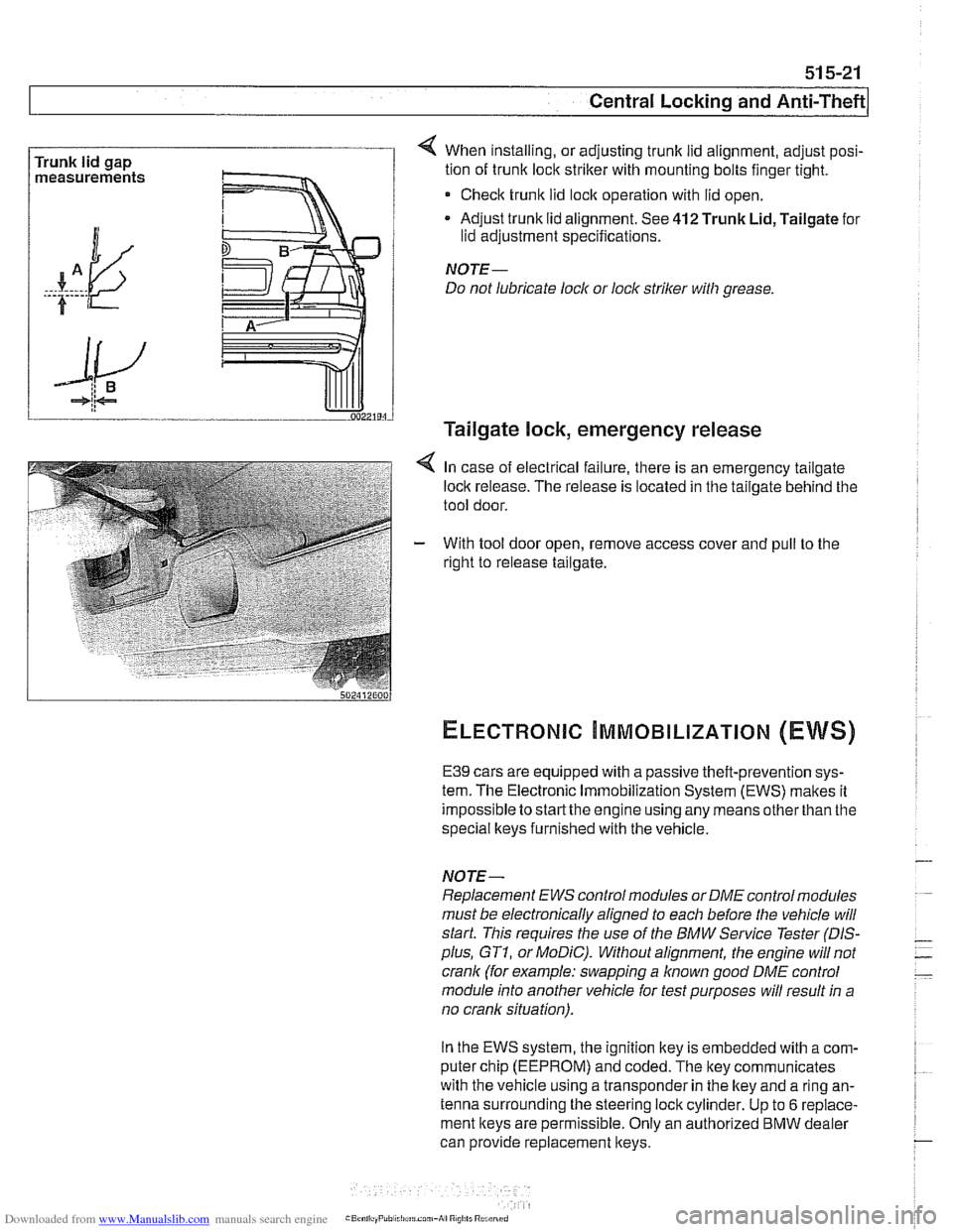
Trunk lid gap
measurements 4 When installing, or adjusting trunk lid alignment, adjust posi-
tion of trunk
loclc striker with mounting bolts finger tight.
* Check trunk lid loclc operation with lid open.
Adjust trunk lid alignment. See
412 Trunk Lid, Tailgate for
lid adjustment specifications.
NOTE-
Do not lubricate lock or lock striker with grease.
Tailgate lock, emergency release
4 In case of electrical failure, there is an emergency tailgate
loclk release. The release is located in the tailgate behind the
tool door.
- With tool door open, remove access cover and pull to the
right to release tailgate.
ELECTRONIC ~MMOBILIZATION (EWS)
E39 cars are equipped with a passive theft-prevention sys-
tem. The Electronic Immobilization System (EWS) makes it
impossible to
startthe engine using any means other than the
special lkeys furnished with the vehicle.
NOTE-
Replacement EWS control modules or DME control modules
must be electronically aligned to each before the vehicle will
start. This requires the use of the BMW Service Tester
(DIS-
plus, GT1, or MoDiC). Without alignment, the engine will not
crank (for example: swapping a
known good DME control
module into another vehicle for test purposes will result in a
no crank situation).
In the EWS system, the ignition key is embedded with
acom-
puter chip (EEPROM) and coded. The key communicates
with the vehicle using a transponder in the lkey and a ring an-
tenna surrounding the steering lock cylinder. Up to
6 replace-
ment keys are permissible. Only an authorized
BMW dealer
can provide replacement keys.
Page 931 of 1002
Downloaded from www.Manualslib.com manuals search engine
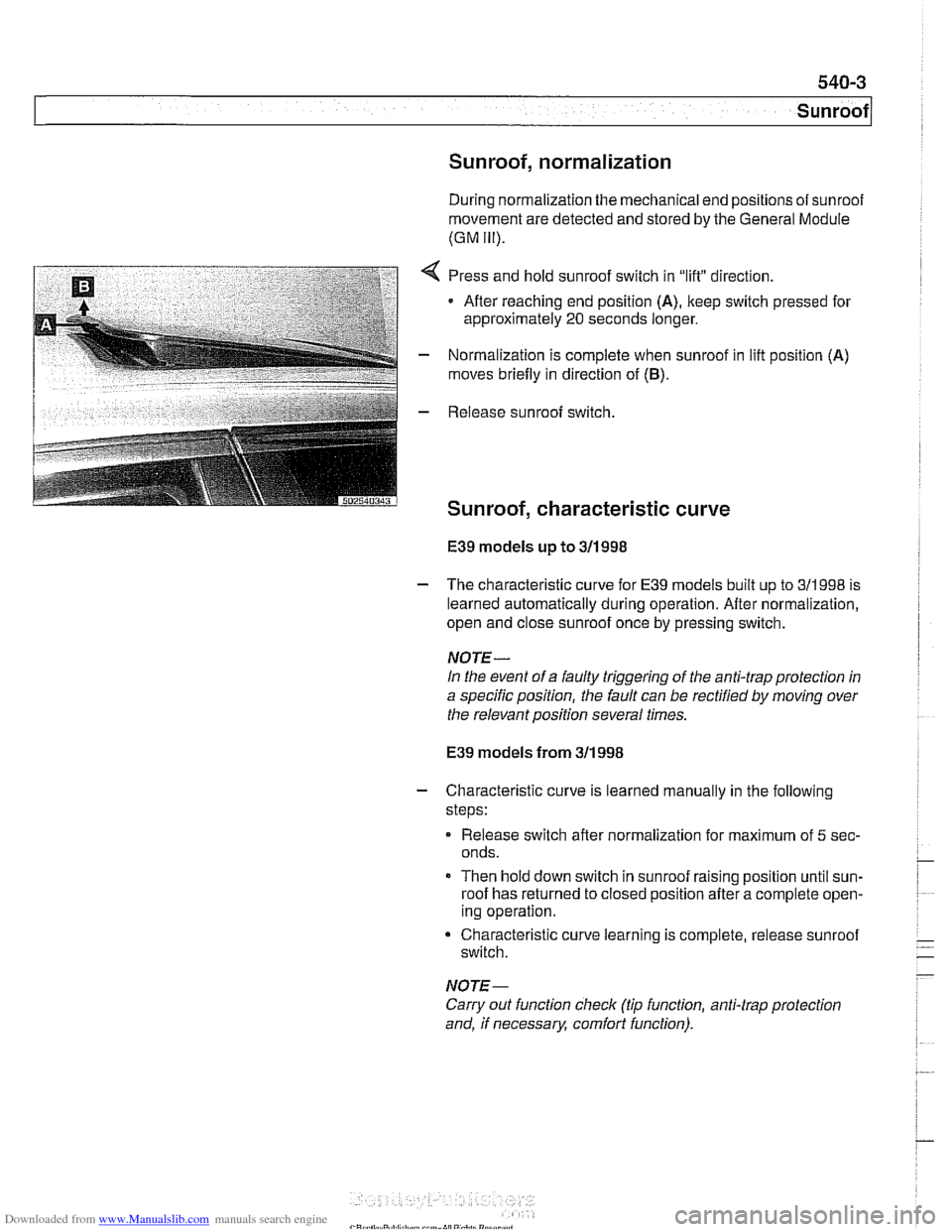
Sunroof, normalization
During normalization the mechanical end positions of sunroof
movement are detected and stored by the General Module
(GM
Ill).
,:..I:,* *:3F$&-T , a,.,-. . 2 *i;.'I . :i_(,*,,_ _* Press and hold sunroof switch in "lift" direction.
Afler reaching end position
(A), keep switch pressed for
approximately
20 seconds longer.
- Normalization is complete when sunroof in lifl position (A)
moves briefly in direction of (6).
E39 models up to 311 998
- The characteristic curve for E39 models built up to 311998 is
learned automatically during operation. After normalization,
open and close sunroof once by pressing switch.
NOTE-
In the event of a faulty triggering of the anti-trap protection in
a specific position, the fault can be rectified
by moving over
the relevant position several times.
E39 models from 311 998
- Characteristic curve is learned manually in the following
steps:
Release switch after normalization for maximum of
5 sec-
onds.
Then hold down switch in sunroof raising position until sun-
roof has returned to closed position after a complete open-
ing operation.
Characteristic curve learning is complete, release sunroof
switch.
NOTE-
Carry out function check (tip function, anti-trap protection
and, if necessary, comfort function).
Page 933 of 1002
Downloaded from www.Manualslib.com manuals search engine
Sunroof, adjusting
The sunroof is controlled by a set of cables that move the sun-
roof panel along guide rails when the motor is operated. The
sunroof can be adjusted without removing it from the car.
NOTE-
Be sure to check drains in front corners of sunroof carrier if
water is entering car through headliner.
- The sunroof panel should be adjusted under the following cir-
cumstances:
Sunroof misaligned with roof.
Sunroof does not close squarely.
* Wind noise at high speeds (sunroof closed).
Sunroof has been removed.
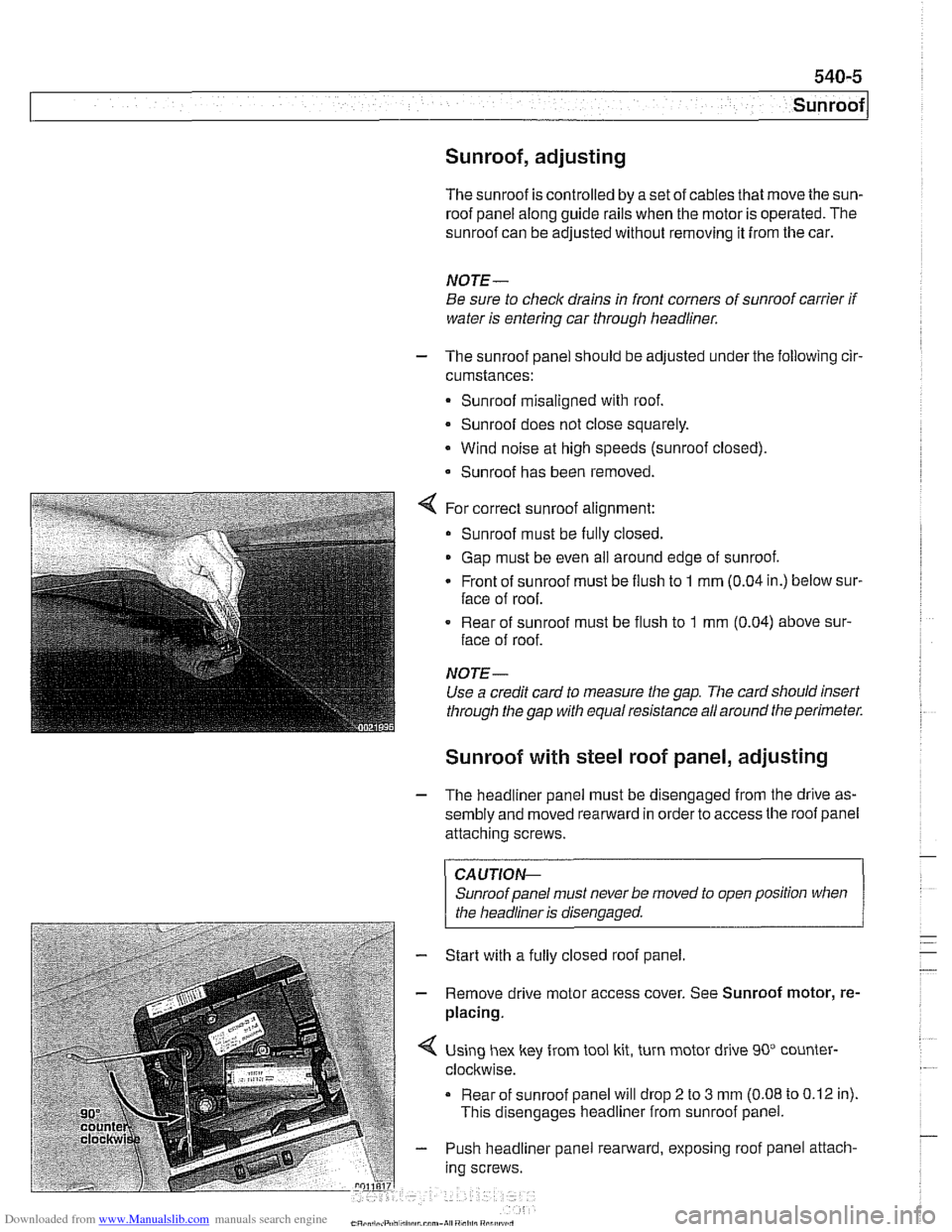
For correct sunroof alignment:
Sunroof must be fully closed.
Gap must be even all around edge of sunroof.
Front of sunroof must be flush to
1 mm (0.04 in.) below sur-
face of roof.
. Rear of sunroof must be flush to 1 mm (0.04) above sur-
face of roof.
NOTE-
Use a credit card to measure the gap. The card sllould insert
through the gap with equal resistance all around the perimeter.
Sunroof with steel roof panel, adjusting
- The headliner panel must be disengaged from the drive as-
sembly and moved rearward in order to access the roof panel
attaching screws.
CAUTIOI\C
Sunroof panel must never be moved to open position when . .
I the headliner is disenaaaed. 1
- Start with a fully closed roof panel.
- Remove drive motor access cover. See Sunroof motor, re-
placing.
Using hex key from tool kit, turn motor drive 90" counter-
clockwise.
Rear of sunroof panel will drop
2 to 3 mm (0.08 to 0.12 in).
This disengages headliner from sunroof panel.
- Push headliner panel rearward, exposing roof panel attach-
ing screws.
Page 940 of 1002
Downloaded from www.Manualslib.com manuals search engine
I Seat Belts
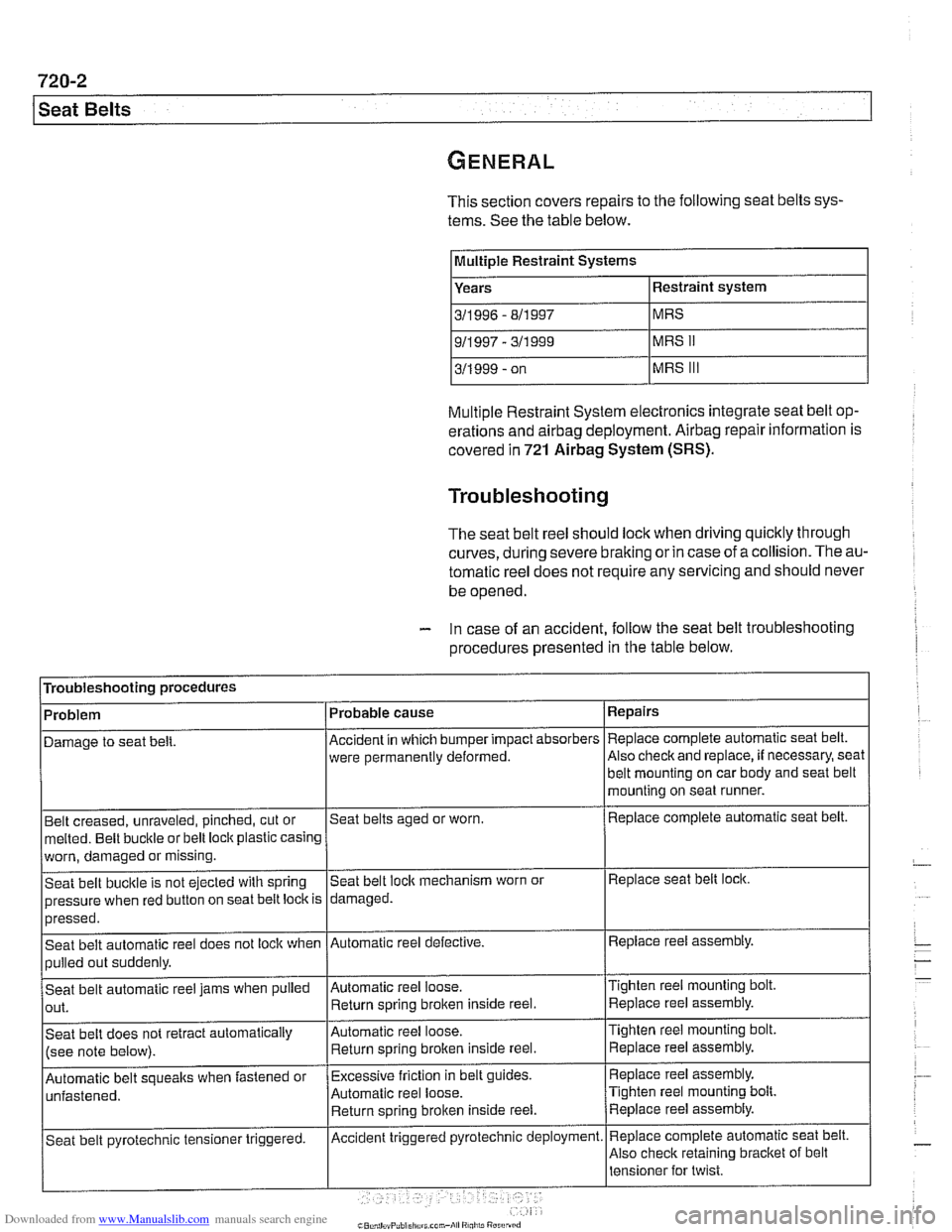
This section covers repairs to the following seat belts sys-
tems. See the table below.
IMultIple Restraint Systems I
Years
311 996 - 811 997
Multiple Restraint System electronics integrate seat belt op-
erations and
airbag deployment. Airbag repair information is
covered
in 721 Airbag System (SRS).
Troubleshooting
The seat belt reel should lock when driving quicltly through
curves,
during severe braking or in case of a collision. The au-
tomatic reel does not require any servicing and should never
be opened.
- In case of an accident, follow the seat belt troubleshooting
procedures presented
in the table below.
Troubleshooting procedures
Belt creased, unraveled, pinched, cut or
melted. Belt buckle or belt loclt plastic casing Repairs
Replace complete automatic
seat belt.
Also
checlt and replace, if necessary, seat
Problem
Damage to seat
belt.
worn, damaged or missing.
Seat belt bucltle is not ejected with spring
pressure when red button on seat belt loclt is
>--- I I
Automatic belt soueaks when fastened or I~xcessive friction in belt guides. I Replace reel assembly.
Probable
cause
Accident in which bumper impact absorbers
were permanently deformed.
Seat belts aged or worn.
pressed.
Seat belt automatic reel does not lock when
pulled out suddenly.
Seat belt automatic reel jams when pulled
out.
Seat belt does not retract automatically
(see note below).
Automatic reel loose. Return sorino broken inside reel. belt mounting on car body and
seat belt
mounting on seat runner.
Replace complete automatic seat belt.
Seat belt
loclt mechanism worn or
damaged.
Tighten reel mounting bolt Replace reel assembly.
Replace seat belt lock.
Automatic reel defective.
Automatic reel loose. Return spring
broken inside reel.
Automatic reel loose.
Return spring brolten inside reel. Replace reel
assembly.
Tighten reel mounting
bolt.
Replace reel assembly.
Tighten reel mounting bolt. Replace reel assembly.
~ ~-~~ , - I'
Replace complete automatic seat belt.
Also check retaining bracket of belt
Seat belt
pyrotechnic tensioner triggered. Accident triggered pyrotechnic deployment.
Page 957 of 1002
Downloaded from www.Manualslib.com manuals search engine
721 -9
Airbaq System ~SRS)~
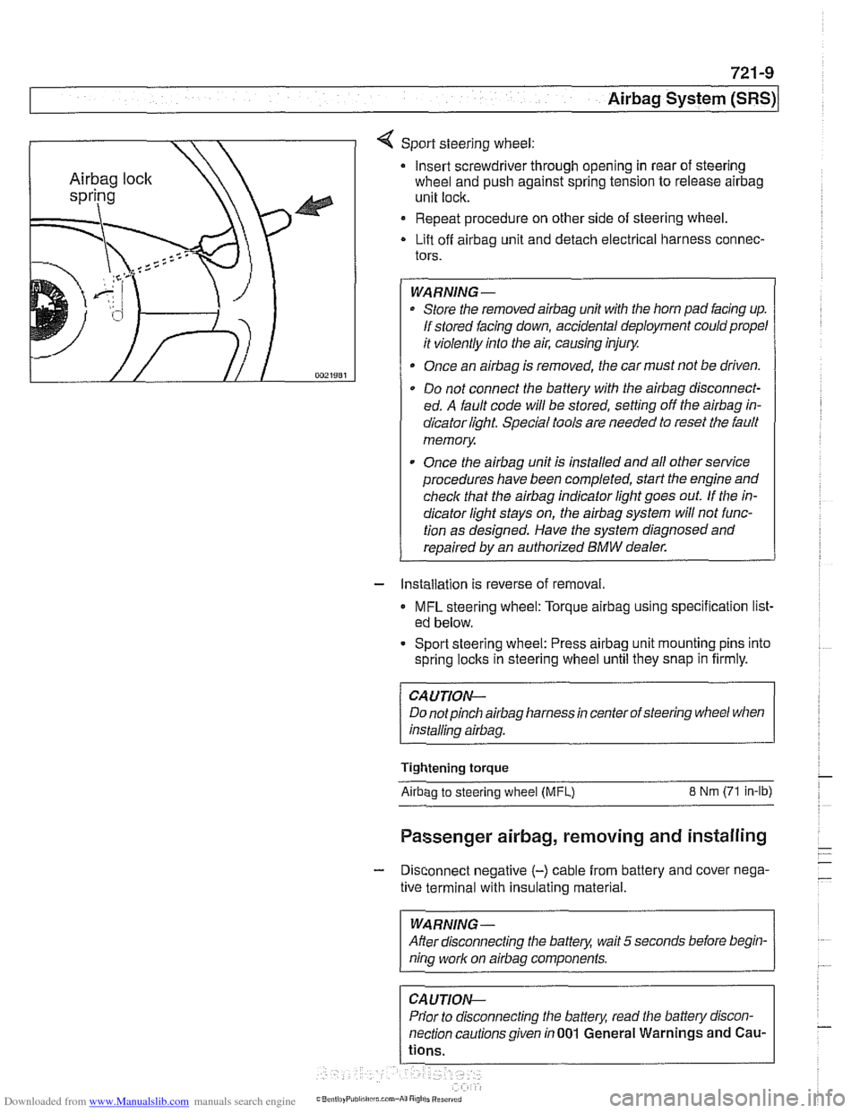
4 Sport steering wheel:
Insert screwdriver through opening in rear of steering
wheel and push against spring tension to release
airbag
unit lock.
Repeat procedure on other side of steering wheel.
Lift off
airbag unit and detach electrical harness connec-
tors.
WARNING-
Store the removedairbag unit with the horn pad facing up.
If stored facing down, accidental deployment could propel
it violently into the air, causing injury.
Once an
airbag is removed, the car must not be driven.
Do not connect the battery with the
airbag disconnect-
ed. A fault code will be stored, setting off the
airbag in-
dicator light Special tools are needed to reset the fault
memory
Once the
airbag unit is installed and all other service
procedures have been completed, start the engine and
check that the
airbag indicator light goes out. If the in-
dicator light stays on, the
airbag system will not func-
tion as designed. Have the system diagnosed and
repaired by an authorized
BMW dealer.
- Installation is reverse of removal.
MFL steering wheel: Torque airbag using specification list-
ed below.
- Sport steering wheel: Press airbag unit mounting pins into
spring
loclts in steering wheel until they snap in firmly.
CAUTION--
Do notpinch airbag harness in center of steering wheel when
installino
airbaa.
Tightening torque
Airbao to steerino wheel IMFL) 8 Nm (71 in-lb)
Passenger airbag, removing and installing
- Disconnect negative (-) cable from battery and cover nega-
tive terminal with insulating material.
--
WARNING -
After disconnecting the batteg wait 5 seconds before begin-
nina work on airbaa components.
Prior to disconnecting the battery, read the battery discon-
nection cautionsgiven in001 General Warnings and
Cau-
Page 961 of 1002
Downloaded from www.Manualslib.com manuals search engine
OBD On-Board Diagnostics
I I
General ........................... OBD-1 Diaqnostic Trouble Codes (DTCs) . . OBD-9
On-Board Diagnostics (OBD I!) ..... OBD-I
Malfunction Indicator Light (MIL)
........ OBD-2
Scan tools and scan tool display.
........ OBD-3
Diagnostic monitors
.................. OED-4
Drive cycle
......................... OED-6
Readiness codes
.................... OBD-6
Diagnostic trouble codes
(DTCs) ........ OBD-7
-
Automatic transmission diagnostic
trouble codes
....................... OBD-9
Engine diagnostic trouble
codes: M52 engine.
................. OED-13
Engine diagnostic trouble
codes: M54 engine.
................. OBD-17
Engine diagnostic trouble
codes: M62 engine.
................. OBD-24
This chapter outlines the fundamentals and equipment
requirements of On-Board Diagnostics
I1 (OBD 11) standards
as they apply to BMW vehicles. Also covered here is a listing
of BMW and OBD
I1 diagnostic trouble codes (DTCs).
ON-BOARD DIAGNOSTICS (QBD !I)
OBD II standards were developed by the SAE (Society of
Automotive Engineers) and CARB (California Air Resources
Board).
OED I1 is the second generation of on-board self-
diagnostic equipment requirements. These standards were
originally mandated for California vehicles. Since
1996 they
have been applied
toall passengervehicles sold in the United
States.
On-board diagnostic capabilities are incorporated into the
hardware and soflwareof the enginecontrol module
(ECM) to
monitor virtually every component that can affect vehicle
emissions. The
OED I1 system works to ensure that
emissions remain as clean as possible over the life of the
vehicle.
Each emission-influencing component is checked by a
diagnostic routine (called a monitor) to verify that it is
functioning properly.
If a problem or malfunction is detected,
the
diagnostic executive built into the OBD I1 system
illuminates a malfunction indicator light (MIL) on the
instrument panel.
The OBD
I1 system also stores diagnostic trouble codes
(DTCs) about the detected malfunction in the ECM so that a
repair technician can accurately find and fix the problem.
Page 962 of 1002
Downloaded from www.Manualslib.com manuals search engine
OED-2
On-Board Diagnostics
Specialized OED II scan tool equipment is needed to access
the fault memory and
OED I1 data.
The extra hardware needed to operate the OED
I1 system
consists mainly of the following:
* Additional oxygen sensors downstream of the catalytic
converters.
Fuel tank pressure sensor and device to pressurize
fuel
storage system.
Several engine and performance monitoring devices
Standardized 16-pin
OED II connector under the
dashboard.
Upgraded components for the federally required reliability
mandate.
Malfunction indicator light (MIL)
OED II software illuminates the malfunction indicator light
(MIL) when emission levels exceed 1.5 times Federal
standards.
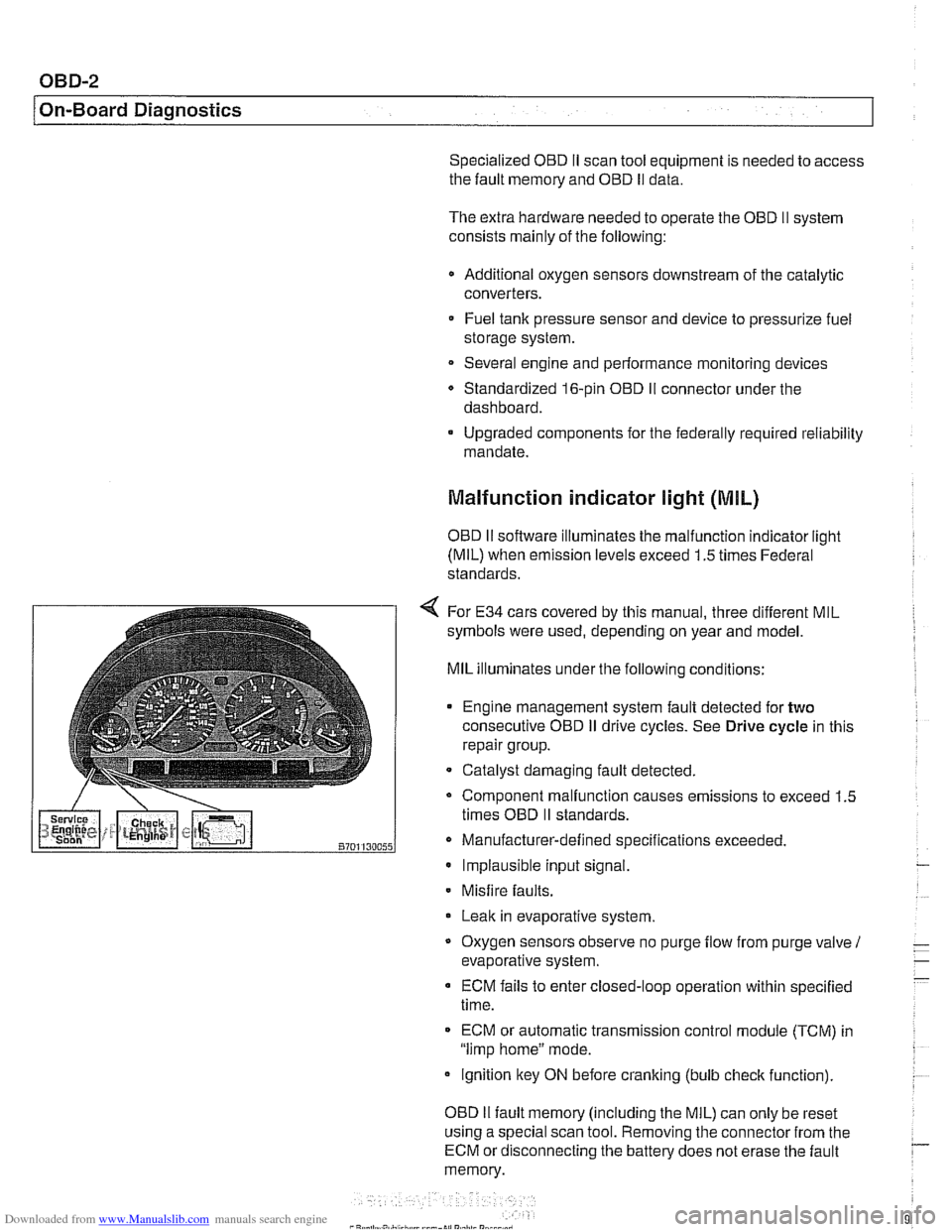
4 For E34 cars covered by this manual, three different MIL
symbols were used, depending on year and model.
MIL illuminates under the following conditions:
Engine management system fault detected for
two
consecutive OED iI drive cycles. See Drive cycle in this
repair group.
- Catalyst damaging fault detected.
Component malfunction causes emissions to exceed 1.5
times OED
II standards.
Manufacturer-defined specifications exceeded. Implausible input signal.
Misfire
faults.
Leak in evaporative system,
Oxygen sensors observe no purge
flow from purge valve 1
evaporative system.
ECM fails to enter closed-loop operation within specified
time.
ECM or automatic transmission control
module (TCM) in
"limp home" mode.
ignition key ON before cranking (bulb
check function).
OED
II fault memory (including the MIL) can only be reset
using a special scan tool. Removing the connector from the
ECM or disconnecting the battery does not erase the fault
memory.
Page 963 of 1002
Downloaded from www.Manualslib.com manuals search engine
OBD-3
On-Board
~iactnosticsl
Additional MIL information:
A fault code is stored within the ECM upon the first
occurrence of a fault in the system being checlted.
Two complete consecutive drive cycles with the iault
present illuminate the MIL. The exception to the two-fault
requirement is a catalyst-damaging fault, which illuminates
the MIL immediately.
If the second drive cycle was not complete and the fault
was not checked, the ECM counts the third drive cycle as
the next consecutive drive cycle. The MIL illuminates
if the
system is checked and the fault is still present.
Once the MIL is illuminated, it remains illuminated until the
vehicle completes three consecutive drive cycles without
detecting a fault.
0 An existing fault code is cleared from memory
automatically when the vehicle completes
40 consecutive
drive cycles without the fault being detected.
In order to automatically clear a catalyst-damaging fault from
memory, the condition underwhich the fault occurred must be
evaluated for 80 consecutive drive cycles without the fault
reoccurring.
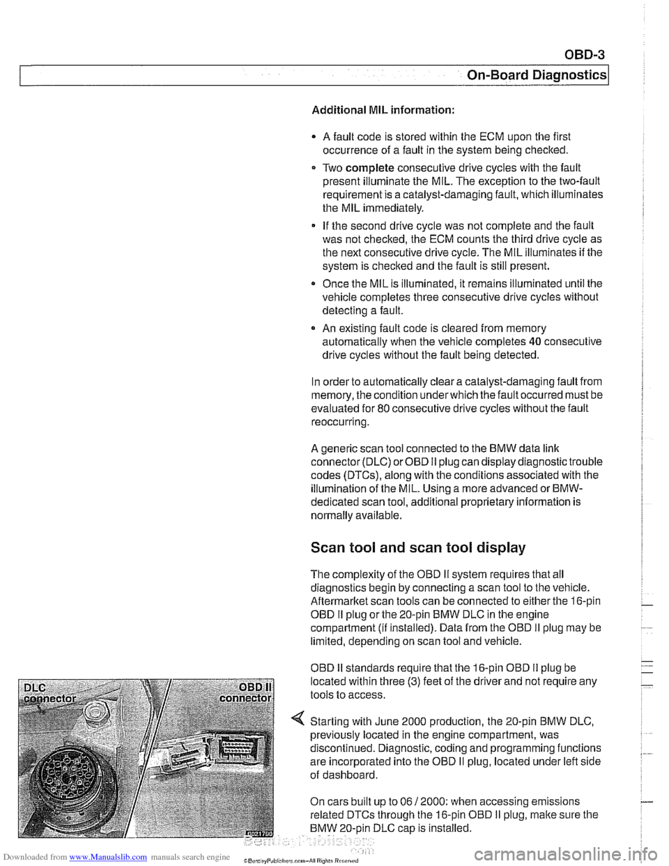
A generic scan tool connected to the BMW data link
connector (DLC) or OBD
I1 plug can display diagnostic trouble
codes (DTCs), along with the conditions associated with the
illumination of the MIL. Using a more advanced or
BMW-
dedicated scan tool, additional proprietary information is
normally available.
Scan tool and scan tool display
The complexity of the OBD I1 system requires that all
diagnostics begin by connecting a scan tool to the vehicle.
Aftermarltet scan tools can be connected to either the 16-pin
OBD
I1 plug or the 20-pin BMW DLC in the engine
compartment
(ii installed). Data from the OBD II plug may be
limited, depending on scan tool and vehicle.
OBD
I1 standards reouire that the 16-oin OBD I1 oluo be
located within three
(3) feet of the driier and not're&ire any
tools to access.
Starting with June 2000 production, the 20-pin BMW DLC,
previously located in the engine compartment, was
discontinued. Diagnostic, coding and programming functions
are incorporated into the OBD
II plug, located under left side
of dashboard.
On cars built up to 06
/ 2000: when accessing emissions
related DTCs through the 16-pin OBD
I1 plug, malte sure the
BMW 20-oin DLC
caD is installed.
Page 964 of 1002
Downloaded from www.Manualslib.com manuals search engine
- -
On-Board Diagnostics
Professional diagnostic scan tools available atthe time of this
printing include the BMW factory tools
(DISplus, GTI,
MoDiC) and a small number of aftermarket BMW-specific
tools. See
020 Maintenance.
In addition to the professional line of scan tools, inexpensive
generic OBD
II scan tool software programs and handheld
units are readily available. Though limited, they are
nonetheless powerful diagnostic tools. These tools read live
data streams and freeze frame data as well as a host of other
valuable diagnostic data.
Diagnostic monitors
Diagnostic monitors run tests and checks on specific
emission control systems, components, and functions.
A complete drive cycle is requiredforthe tests to bevalid. See
Drive cycle in this repair group. The diagnostic monitor
signals the
ECM of the loss or impairment of the signal or
component and determines if a signal or sensor is faulty
based on
3 conditions:
* Signal or component shorted to ground
Signal or component shorted to
B+
Signal or component missing (open circuit)
The OBD
II system monitors all emission control systems that
are installed. Emission control systems vary by vehicle model
and year. For example, a vehicle may not be equipped with
secondary air injection, so no secondary air readiness code
would be present.
OBD
II software monitors the following:
Oxygen sensors
Catalysts
Engine misfire
- Fuel tank evaporative control system
Secondary air injection Fuel system
Oxygen sensor monitoring. When driving conditions allow,
response rate and switching time of each oxygen sensor is
monitored. The oxygen sensor heater function is also
monitored. The OBD
II system differentiates between
precataylst and post-catalyst oxygen sensors and reads each
one individually. In order
forthe oxygen sensor to be
effectively monitored, the system must be in closed loop
operation.
Page 966 of 1002
Downloaded from www.Manualslib.com manuals search engine
OBD-6
On-Board Diagnostics
Fuel system monitoring. This monitor looks at the fuel
delivery needed (long
/short term fuel trim) for proper engine
operation based on programmed data. If too much or not
enough fuel is delivered over a predetermined time, a DTC is
set and the MIL illuminates.
Fuel trim refers to adiustments to base fuel schedule.
Lono- ., term fuel trim refers to gradual adjustments to the fuel
calibration adjustment as compared to short term fuel trim.
Long term fuel trim adjustments compensate for gradual
changes that occur over time.
Fuel system monitoring monitors the calculated injection time
(ti) in relation to enginespeed, load and precatalyticconverter
oxygen
sensor(s) signals.
Using this data, the system optimizes fuel delivery for all
engine operating conditions.
Evaporative system monitoring. This monitor checks the
the fuel storage system and related fuel lines for leaks. It can
detect very small leaks anywhere in the system.
A leak detection unit (LDP or DMTL) is used to pressurize the
evaporative control system on a continuous basis (as the
drive cycle allows) and to
check system integrity.
Drive cycle
The OED II drive cycle is an important concept in
understanding OBD
II requirements. The purpose of the drive
cycle is to run ail of the emission-related on-board diagnostics
over a broad range of driving conditions.
A drive cycle is considered complete when all of the
diagnostic monitors have run their tests without interruption.
~ora drive cycle to be initiated, the vehicle must be started
cold and brought up to
1 60°F and at least 40°F above its
original starting temperature.
Readiness codes
Inspection/maintenance (I/M) readiness codes are mandated
as part of OBD
II. The readiness code is stored aftercomplete
diagnostic monitoring of specified components and systems
is carried out. The readiness code function was designed to
prevent manipulating an
I/M emission test procedure by
clearing faults codes or disconnecting the ECM or battery.