check engine BMW 528i 1998 E39 Workshop Manual
[x] Cancel search | Manufacturer: BMW, Model Year: 1998, Model line: 528i, Model: BMW 528i 1998 E39Pages: 1002
Page 691 of 1002
Downloaded from www.Manualslib.com manuals search engine
Steerina and Wheel ~lianmentl
Proper handling, stability and driving ease depend upon the
correct alignment of all four wheels. The front axle is aligned
in relation to the rear axle, then the front wheels are aligned in
relation to one another. This is known as a four-wheel or
thrust-axis alignment.
Front and rear alignment specification are given in tables at
the end of this repair group.
BMW E39 cars use a sophisticated multi-link suspension at
the front and rear of the car. Proper alignment requires com-
puterized alignment equipment.
Camber
Front wheel camber is set at the factory and cannot be adjust-
ed. Rear wheel camber is fully adjustable.
Always set rear camber before adjusting toe
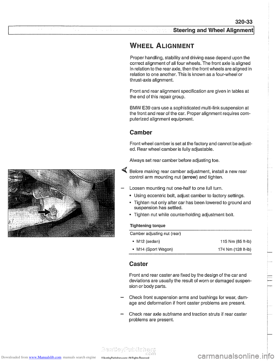
Before making rear camber adjustment, install a new rear
control arm mounting nut
(arrow) and tighten.
- Loosen mounting nut one-half to one full turn.
Using eccentric bolt, adjust camber to factory settings.
Tighten nut only after car has been lowered to ground and
suspension has settled.
Tighten nut while counterholding adjustment bolt.
Tightening torque
Camber adjusting nut (rear)
MI2 (sedan)
- MI4 (Sport Wagon)
115 Nm (85 ft-lb)
174 Nm (128 ft-lb)
Caster
Front and rear caster are fixed by the design of the car and
deviations are usually the result of worn or damaged suspen-
sion or body parts.
- Check front suspension arms and bushings for wear, dam-
age and deformation if front caster problems are present.
- Check rear axle subfrarne and traction struts if rear caster
problems are present.
Page 709 of 1002
Downloaded from www.Manualslib.com manuals search engine
330-1 3
Rear Suspension
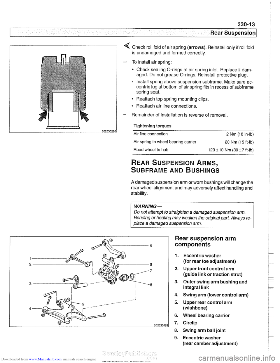
1 1 4 Check roll fold of air spring (arrows). Reinstall only if roll fold
is undamaged and formed correctly.
- To install air spring:
Check sealing O-rings at air spring inlet. Replace
if dam-
aged. Do not grease O-rings. Reinstall protective plug.
* Install spring above suspension subframe. Make sure ec-
centric lug at bottom of air spring fits in recess of
subframe
spring seat.
Reattach top spring mounting clips.
- Reattach air line connections.
- Remainder of installation is reverse of removal.
Tightening torques
Air line connection
2 Nm (1 8 in-lb)
Air spring
to wheel bearing carrier 20 Nm (1 5 ft-lb)
Road
wheel to hub 120 510 Nm (89-F-7 ft-lb)
REAR SUSPENSION ARMS,
SUBFRAME AND BUSHINGS
A damaged suspension arm orworn bushings will change the
rear wheel alignment and may adversely affect handling and
stability.
WARNING-
Do not attempt to straighten a damaged suspension arm.
Bending or heating may
weaken the original part. Always re-
olace a damaoed susoension arm.
Rear suspension arm
components
1. Eccentric washer
(for rear toe adjustment)
2. Upper front control arm
(guide link or traction strut)
3. Outer swing arm bushing and
integral link
4. Swing arm (lower control arm)
5. Upper rear control arm
(wishbone)
6. Wheel bearing carrier
7. Circlip
8. Swing arm ball joint
9. Eccentric washer
(rear camber adjustment)
Page 745 of 1002
Downloaded from www.Manualslib.com manuals search engine
33UFinal Drive
General ........................... ,331 -2 Drive Axles ....................... 331 -1 4
Special tools
........................ ,331 -2 Drive axle assembly ................. 331-14
Aluminum suspension components
...... ,331-4 Drive axle, removing and
installing (sedan)
.................... 331-14 ........................ Final Drive ,331 -5
Drive axle, removing
........... ...... Final drive, removing and installing ,331-5 and (Sport Wagon) 331-15
...................... Differential oil level, checking ........... ,331-6 CV joint boots 331-17 Final drive in~ut shaft seal, replacing ..... ,331-7 .
Final drive oitput shaft seals, replacing . . ,331-10
Final drive cover, removing and installing ,331-12
Final drive mounts, replacing .......... ,331-12
Page 749 of 1002
Downloaded from www.Manualslib.com manuals search engine
Final Drive
Final drive, removing and installing
- Raise rear of car.
WARNING-
Make sure that the car is firmly supported on jack stands de-
signed for the purpose. Place the jaclc stands beneath struc-
tural chassis
~oints. Do not i lace iaclc stands under
( suspension barfs.
Remove exhaust system. See 180 Exhaust System.
Disconnect drive shaft from final drive. See
260 Driveshaft.
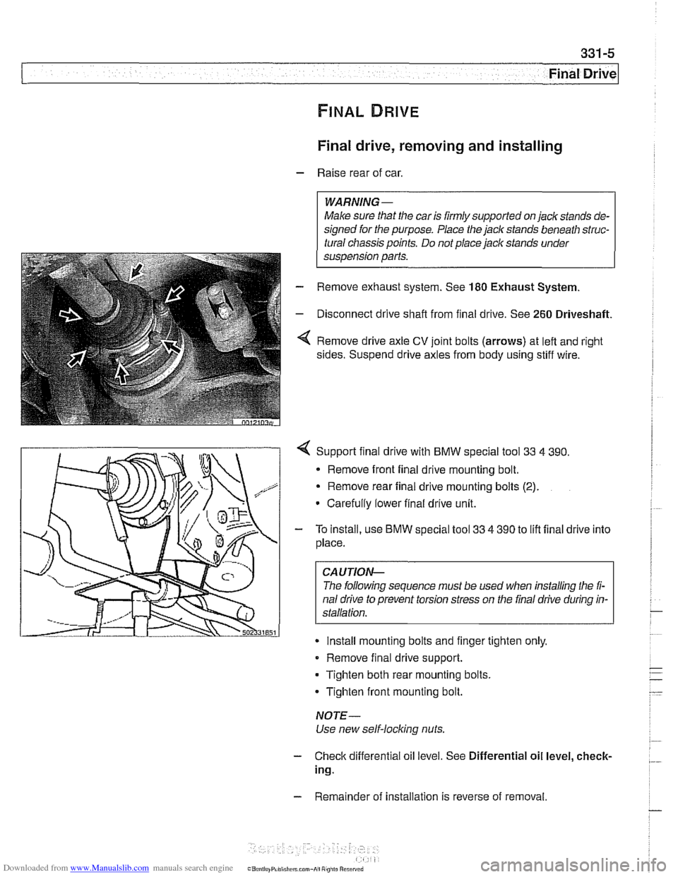
Remove drive axle CV joint bolts (arrows) at left and right
sides. Suspend drive axles from body using stiff wire.
4 Support final drive with BMW special tool 33 4 390.
* Remove front final drive mounting bolt.
Remove rear final drive mounting bolts
(2).
Carefully lower final drive unit.
- To install, use BMW special tool 33 4 390 to lift final drive into
place.
CA UTIOP&
The following sequence must be used when installing the fi-
nal drive to prevent torsion stress on the final drive during in-
Install mounting bolts and finger tighten only.
Remove final drive support.
Tighten both rear mounting bolts.
Tighten front mounting bolt.
NOTE-
Use new self-locking nuts.
- Check differential oil level. See Differential oil level, check-
ing.
- Remainder of installation is reverse of removal.
Page 750 of 1002
Downloaded from www.Manualslib.com manuals search engine
Final Drive
Tightening torques
F~nal drive to rear axle carrier 105 Nm (77 it-lb)
Driveshaft CV joint to final drive flange
- MlO (Torx bolt) 70
Nm (51 ft-lb)
- M8 (compression nut) 32 Nm (24
ft-lb)
Drive axle to final drive
ilange
Torx bolts (M10) 83 Nm (61 ft-lb)
Torx bolt with
rlbbed teeth (M10) 64 Nm (47 ft-lb)
Torx bolt
wlth ribbed teeth (MI0 sliver) 80 Nm (59 ft-lb)
Torx
bolt with ribbed teeth (M10 black) 100 Nm (74 ft-lb)
* Torx bolt with ribbed teeth (M12) 135 Nm (100 ft-lb)
Differential oil level, checking
The E39 differential is filled with lifetime oil that ordinarily
does not need to be changed. BMW recommends using only
a specially formulated synthetic gear oil
(SAF-XO) that is
available through an authorized BMW dealer parts depart-
ment. For additional information on this lubricant and any oth-
er lubricants that may be compatible, contact an authorized
BMW dealer service department.
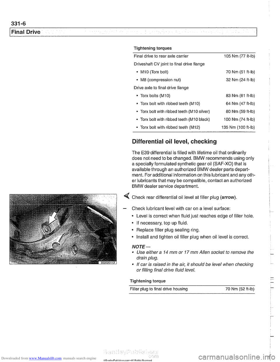
< Check rear differential oil level at filler plug (arrow).
- Check lubricant level with car on a level surface:
Level is correct when fluid just reaches edge of filler hole.
If necessary, top up fluid.
* Replace filler plug sealing ring.
Install and tighten oil filler plug when oil level is correct.
NOTE-
Use either a 14 mm or 17 mm Allen socket to remove the
drain plug.
If car is raised in the air. it should be level when
checkino " or filling final drive fluid level.
- Tightening torque -
Filler plug to final drive housing 70 Nm (52
ft-lb) -
Page 753 of 1002
Downloaded from www.Manualslib.com manuals search engine
331-9
Final Drive
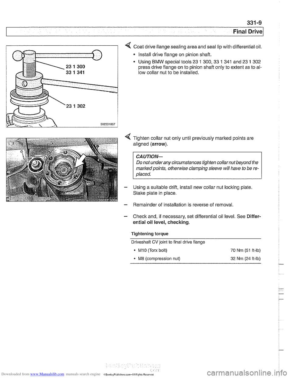
Coat drive flange sealing area and seal lip with differential oil.
* Install drive flange on pinion shaft.
Using
BMW special tools 23 1 300,33 1 341 and 23 1 302
press drive flange on to pinion shaft only to extent as to al-
low collar nut to be installed.
4 Tighten collar nut only until previously marked points are
aligned (arrow).
CAUTION-
Do not underany circumstances tighten collarnut beyond the
markedpoints,
othe~lise clamping sleeve will have to be re-
placed.
- Using a suitable drift, install new collar nut locking plate
Stalte plate in place.
- Remainder of installation is reverse of removal.
- Check and, if necessary, set differential oil level. See Differ-
ential oil level, checking.
Tightening torque Driveshaft
CV joint to final drive flange
MI0 (Torx bolt) 70 Nrn (51 ft-lb)
ME (compression nut) 32 Nrn (24 ft-lb)
Page 755 of 1002
Downloaded from www.Manualslib.com manuals search engine
331-1 1
Final rive(
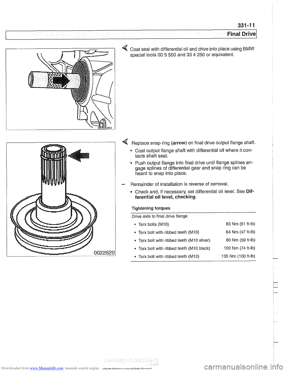
< Coat seal with differential oil and drive into place using BMW
special tools 00 5 500 and 33 4 250 or equivalent.
Replace snap ring (arrow) on final drive output flange shaft.
Coat output flange
shaft with differential oil where it con-
tacts shaft seal.
. Push output flange into final drive until flange splines en-
gage splines of differential gear and snap ring can be
heard to snap into place.
- Remainder of installation is reverse of removal.
Check and, if necessary, set differential oil level. See Dif-
ferential oil level, checking.
Tightening torques Drive axle to final drive flange
Torx bolts
(M10) 83 Nm (61 ft-lb)
Torx bolt with ribbed teeth (M10) 64 Nm (47 it-lb)
Torx bolt with ribbed teeth (Mi0 silver) 80 Nm (59 ft-lb)
Torx bolt with ribbed teeth (MI0 black) 100 Nm (74 ft-lb)
- Torx bolt with ribbed teeth (M12) 135 Nm (100 ft-lb)
Page 756 of 1002
Downloaded from www.Manualslib.com manuals search engine
331-12
Final Drive Final drive cover, removing and installing
- Remove final drive. See Final drive, removing and install-
ing.
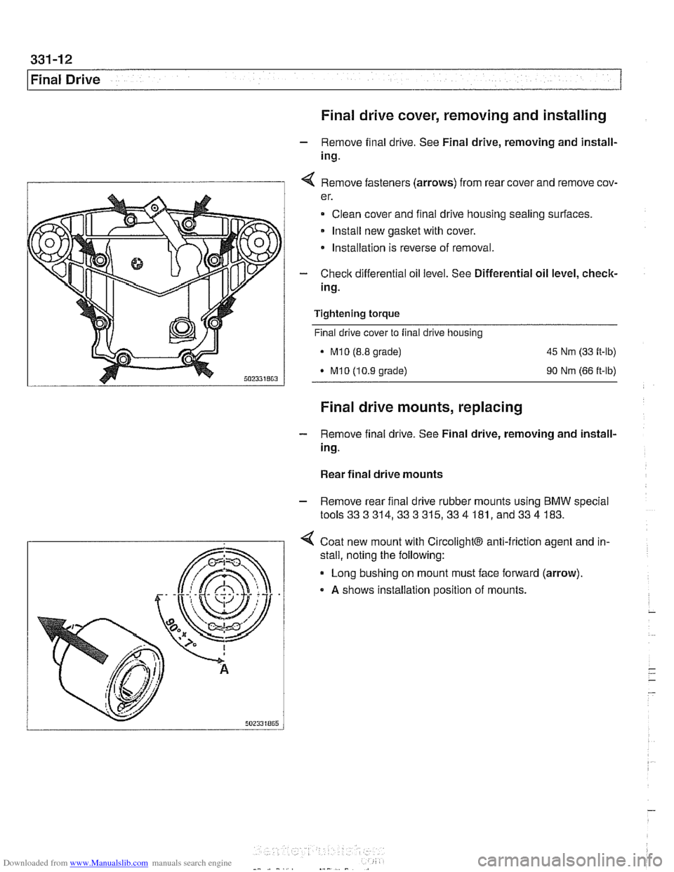
I 1 4 Remove fasteners (arrows) from rear cover and remove cov-
er.
Clean cover and final drive housing sealing surfaces.
Install new
gasket with cover.
* Installation is reverse of removal.
- Check differential oil level. See Differential oil level, check-
ing.
Tightening
torque
Final drive cover to final drive housing
. M10 (8.8 grade) 45 Nm (33 ft-lb)
M10 (10.9 grade) 90 Nm (66 ft-lb)
Final drive mounts, replacing
- Remove final drive. See Final drive, removing and install-
ing.
Rear final drive mounts
- Remove rear final drive rubber mounts using BMW special
tools333314,333315,334 181, and334 183.
4 Coat new mount with CircolightB anti-friction agent and in-
.
stall, noting the following:
Long bushing on mount must face forward (arrow).
A shows installation position of mounts.
Page 763 of 1002
Downloaded from www.Manualslib.com manuals search engine
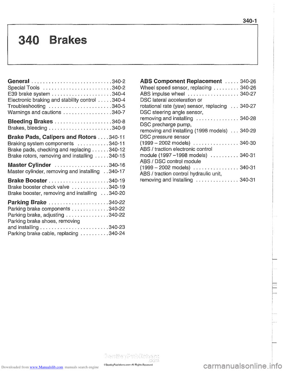
General ........................... .34 0.2
Special Tools
....................... .34 0.2
E39 brake system
.................... .34 0.4
Electronic braking and stability control
.... .34 0.4
Troubleshooting
..................... .34 0.5
Warnings and cautions
................ .34 0.7
Bleeding Brakes ................... .34 0.8
Brakes, bleeding
..................... .34 0.9
Brake Pads, Calipers and Rotors ... .34 0.1 1
Braking system components .......... .34 0.11
Brake pads,
checking and replacing ..... .34 0.12
Brake rotors, removing and installing
.... .34 0.15
Master Cylinder .................. .34 0.16
Master cylinder, removing and installing
. .34 0.17
Brake Booster .................... .349 0.1
Brake booster check valve
............ .34 0.19
Brake booster, removing and installing
.. .34 0.20
Parking Brake .................... .34 0.22
Parking brake components
............ .34 0.22
Parking
brake, adjusting .............. .34 0.22
Parking bralte shoes, removing
and installing
....................... .34 0.23
Parking
brake cable, replacing ......... .34 0.24
ABS Component Replacement ..... 340-26
Wheel speed sensor. replacing
......... 340-26
ABS impulse wheel
.................. 340-27
DSC lateral acceleration or
rotational rate (yaw) sensor. replacing
... 340-27
DSC steering angle sensor.
removing and installing
............... 340-28
DSC precharge pump.
removing and installing (1998 models)
... 340-29
DSC pressure sensor
(1 999 - 2002 models) ................ 340-30
ABS /traction electronic control
module
(1 997 -1 998 models) .......... 340-31
ABS
/ DSC control module
(1 999
- 2002 models) ................ 340-31
ABS
/ traction control hydraulic unit.
removing and installing
............... 340-31
Page 767 of 1002
Downloaded from www.Manualslib.com manuals search engine
Brakes
Troubleshooting
Brake performance is mainly affected by three things:
Q Level and condition of brake fluid
Ability of bralte system to create and maintain pressure
Condition of friction components
Air in bralte fluid will
make the brake pedal feel spongy during
braking
orwill increase the bralte pedal force required to stop.
Fluid contaminated by moisture or dirt can corrode the sys-
tem. lnspect the brake fluid inside the reservoir. If it is dirty or
murky, or is more then two years old, replace fluid.
To
check the function of the master cylinder hold the bralte
pedal down hard with the engine running. If the pedal slowly
falls to the floor, either the master cylinder is leaking internal-
ly, or fluid is leaking externally.
lnspect the rotors for glazing, discoloration and scoring.
Steering wheel vibration while braking at speed is often
caused by warped rotors, but can also be caused by worn
suspension components.
When troubleshooting, keep in mind that tire inflation, wear
and temperature can all have an affect on braking. See
300
Suspension, Steering and Brakes-General for additional
suspension and brake system troubleshooting.
The table Brake system troubleshooting lists symptoms of
brake problems, probable causes, and suggested corrective
actions. Unless noted otherwise, relevant repairs are de-
scribed later in this repair group.