troubleshooting BMW 528i 1998 E39 Owner's Manual
[x] Cancel search | Manufacturer: BMW, Model Year: 1998, Model line: 528i, Model: BMW 528i 1998 E39Pages: 1002
Page 456 of 1002
Downloaded from www.Manualslib.com manuals search engine
Fuel Injection
When system faults are detected, a diagnostic trouble code
(DTC) is stored in the engine control module (ECM). The MIL
also illuminates
if an emissions-related fault is detected.
When faults arise, or
if the malfunction indicator lamp (MIL) is
illuminated, begin troubleshooting by connecting BMW ser-
vice tester
DISplus, MoDiC, GTl or equivalent scan tool. The
capabilities of OBD
II software has the potential to save hours
of diagnostic time and to help avoid incorrect component re-
placement and possible damage to system components.
CA UTIOI\C
The tests in this section may set fault codes (DTCs) in the
ECM and illuminate the MIL. After all testing is completed,
access and clear DTC fault memory using an OBD
I1 or
BMW compatible scan tool. See OBD On-Board Diag-
nostics.
. Only use a digital multimeter for electrical tests.
Relay positions can vary. Be sure to confirm relay posi-
tion by identifying the wiring in the
socket using the wir-
ing diagrams found in ELE Electrical Wiring
Diaqrams.
NOTE-
= OBD I1 fault memory (including an illuminated MIL) can
only be reset using the special scan tool. Removing the
connector from the ECM or disconnecting the battery will
not erase the fault memory.
0 The BMW-dedicated 20-pin diagnostic link connector
(DLC) is in the right rear of the engine compartment. The
20-pin DLC was eliminated on models after
6/2000.
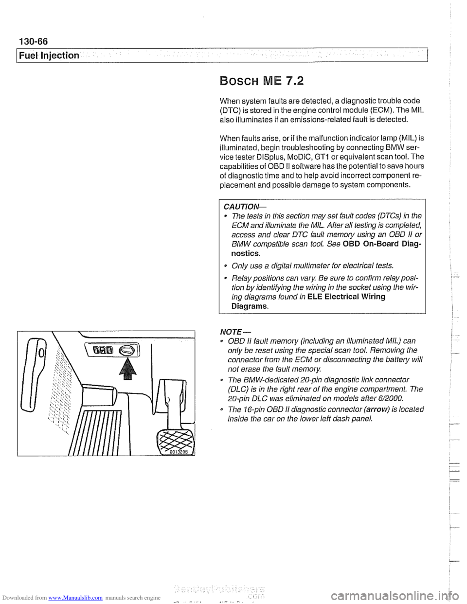
The 16-pin OBD I1 diagnostic connector (arrow) is located
inside the car on the lower left dash panel.
Page 471 of 1002
Downloaded from www.Manualslib.com manuals search engine
160 Fuel Tank and Fuel Pump
General ........................... .I6 0.2
Special tools ........................ .I6 0.2
Fuel pump ......................... .I6 0.3
Fuel tank evaporative control system ..... .I6 0.3
Evaporative system troubleshooting ..... .I6 0.4
Warnings and cautions ................ .I6 0.5
Fuel System Troubleshooting ...... .I6 0.6
Fuel pump fuse and relay .............. .I6 0.6
Operating fuel pump for tests ........... .I6 0.6
Fuel pump electrical circuit, testing ...... .I6 0.7
Fuel pump power consumption, testing ... .I6 0.9
Fuel pressure gauge, installing
(6-cylinder models)
................. .I6 0.1 0
Fuel pressure gauge, installing
(V-8 models) ....................... .I6 0.1 1
Fuel delivery, testing ................ .I6 0.12
Fuel Pump and Fuel Level Sender . . 160-15
Fuel level sender (right side) and
fuel pump. removing and installing
...... 160-15
Fuel level sender (left side).
removing and installing
............... 160-17
Siphon pump. removing and installing .... 160-1 9
Fuel Tank and Fuel Lines .......... 160-20
Fuel tank. draining ................... 160-20
Fuel tank. removing and installing ....... 160-21
Fuel expansion tank. removing
and installing
....................... 160-23
Activated carbon canister I fuel tank
leak detection unit
(LDP or DMTL).
removing and installing ............... 160-24
Running losses (312-way) valve.
removing and installing
............... 160-24
Page 474 of 1002
Downloaded from www.Manualslib.com manuals search engine
Fuel Tank and Fuel Pump
Evaporative system troubleshooting
- Start by accessing diagnostic trouble codes (DTCs) using a
BMW or BMW compatible aftermarket scan tool.
For purposes of OBD
II emissions compliance, the DME
system sets a diagnostic trouble code (DTC) when it de-
tects a leak that is equal or larger than minimum
lealc
sensed by system.
Malfunction Indicator Light (MIL) is illuminated upon sec-
ond recurrence of fault. See OBD On-Board Diagnostics.
- When leak testing, observe following conditions to obtain
plausible results:
Fuel tank
'1, to 'I., full.
0 Vehicle parked for at least 2 hours to allow fuel to reach
room temperature.
Ideal fuel temperature is 10"- 20°C
(50"
- 68" F).
Do not refuel immediately before
lealc test.
- If a leak is detected, check the following areas:
* Fuel filter cap (leaking or off).
Fuel tank ventilation lines leaking at fuel
tank or activated
carbon canister.
i
Tank ventilation valve leaking (in engine compartment).
Fuel level
sensorlfuel pump cap leaking.
Evaporative system component replacement is covered later
in
th~s group in Fuel Tank and Fuel Lines.
Page 476 of 1002
Downloaded from www.Manualslib.com manuals search engine
.-- -
/ Fuel Tank and Fuel Pump - .. -. -- 1
Fuel pump fuse and relay
Troubleshooting of any fuel pump fault should begin with
checking the fuel pump fuse and the fuel pump relay. The
DME main relay should also be checked. The fuel pump relay
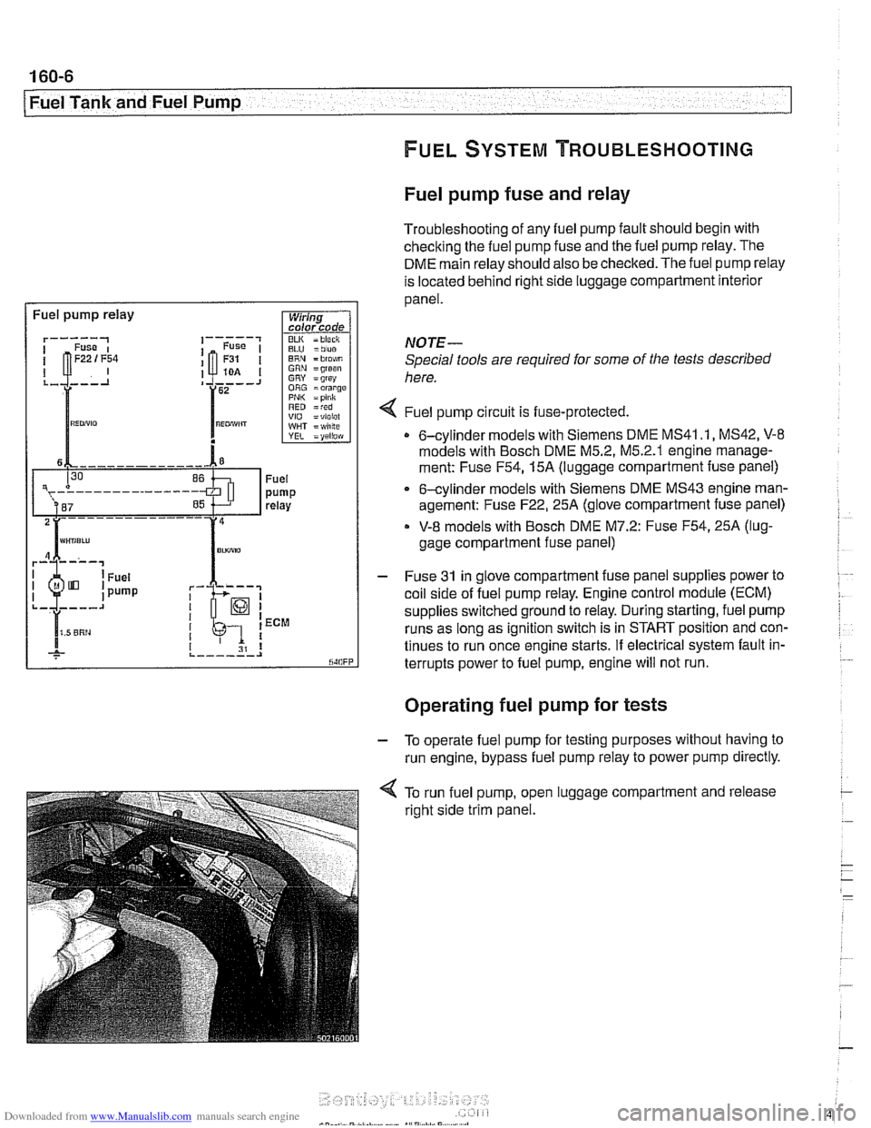
is located behind right side luggage compartment interior
panel.
I Fuel pump relay
BLU =blue ERN = blo$,m GRN =groan GRY = grsy ORG =orange PNI< =pink RED =red VIO =violel WHT = wlilte
rk-; I I 1 ECM
I I I 31 8 ,._--___.I
NOTE-
Special tools are required for some of the tests described
here.
4 Fuel pump circu~t is fuse-protected.
0 6-cylinder models with Siemens DME MS41 .I, MS42, V-8
models with Bosch DME M5.2, M5.2.1 englne manage-
ment: Fuse
F54,15A (luggage compartment fuse panel)
6-cylinder models with Siemens DME MS43 engine man-
agement: Fuse
F22,25A (glove compartment fuse panel)
V-8 models with Bosch DME M7.2: Fuse F54,25A (lug-
gage compartment fuse panel)
- Fuse 31 in glove compartment fuse panel supplies power to
coil side of fuel pump relay. Engine control module (ECM)
supplies switched ground to relay. During starting, fuel pump
runs as long as ignition switch is in START position and con-
tinues to run once engine starts. If electrical system fault in-
terrupts power to fuel pump, engine will not run.
. .
Operating fuel pump for tests
- To operate fuel pump for testing purposes without having to
run engine, bypass fuel pump relay to power pump directly.
< To run fuel pump, open luggage compartment and release
right side trim panel.
Page 497 of 1002
Downloaded from www.Manualslib.com manuals search engine
176 Radiator and Cooling System
General ........................... .I7 0.2
Special tools
........................ .I7 0.2
Cooling system overview
(M52 TU shown. others similar) ......... .I7 0.3
Coolant pump
....................... .I7 0.3
Thermostat
......................... .I7 0.3
Mechanical thermostat (M52 engine)
..... .I7 0.4
Electrically heated thermostat
.......... .I7 0.4
Radiator and expansion tank
........... .I7 0.4
Mechanical cooling fan with viscous clutch
.I7 0.4
Electric (auxiliary) cooling fan ........... .I7 0.4
Transmission fluid heat exchanger
....... .I7 0.5
Warnings and cautions
................ .I7 0.7
Troubleshooting ................... .I7 0.7
Cooling system inspection
............. .I7 0.8
Cooling system pressure test
........... .I7 0.9
Combustion chamber leak test
......... .I7 0.10
Thermostat
........................ .I7 0.1 0
Cooling System Service ........... 170-10
Coolant. draining and filling
(6-cylinder models)
.................. 170-1 0
Coolant. draining and filling (V-8 models)
. 170-12
Cooling system. bleeding
............. 170-14
Mechanical (viscous clutch) cooling fan.
removing and installing
............... 170-14
Electric cooling fan.
removing and installing
............... 170-15
Thermostat. removing and installing
(M52engine) ....................... 170-16
Thermostat. removing and installing
(M52 TU or M54 engine) .............. 170-17
Thermostat. removing and installing (V-8 models)
....................... 170-1 8
Coolant pump. replacing (6-cylinder models)
.................. 170-1 9
Coolant pump. replacing (V-8 models) ... 170-20
Radiator. removing and installing
....... 170-22
Expansion tank. removing and
installing . . 170-24
Page 585 of 1002
Downloaded from www.Manualslib.com manuals search engine
240 Automatic Transmission
General . . . . . . . . . . . . . . . . . . . . . .
Special tools . . . . . . . . . . . . . . . . . . .
Automatic transmission applications
. . . . . ,240-2 ATF, draining and filling . . . . . . . . . . . . . . . . 240-7
. . . . . ,240-2 Automatic transmission fluid
. . . . . ,240-4 pan and strainer. . . . . . . . . . . . . . . . . . . . . . 240-9
Troubleshooting . . . . . . . . . . . . . . . . . . .240-4 Transmission Removal
and Installation
. . . . . . . . . . . . . . . . . . . 240-10 Automatic Transmission Fluid Transmission, removing and installing . . . 240-10 (ATF) Service . . . . . . . . . . . . . . . . . . . . . ,240-6
Automatic transmission fluid (ATF) . . . . . . . ,240-6
ATF level, checking . . . . . . . . . . . . . . . . . . ,240-6
Page 607 of 1002
Downloaded from www.Manualslib.com manuals search engine
................. General ............................ 260-2 Driveshaft. installing 260-10
.................. Special tools ........................ .26 0.2 Flex.disc. replacing 260-1 1
..... Driveshaft description ................. .26 0.3 Center bearing assembly. replacing 260-12
........ Troubleshooting ..................... .26 0.3 Front centering guide. replacing 260-13
Constant velocity
(CV) joint. replacing .... 260-14 Driveshaft Service ................. .26 0.6
Driveshaft. aligning
................... .26 0.7
Driveshaft. removing
................. .26 0.8
Page 609 of 1002
Downloaded from www.Manualslib.com manuals search engine
Driveshaft
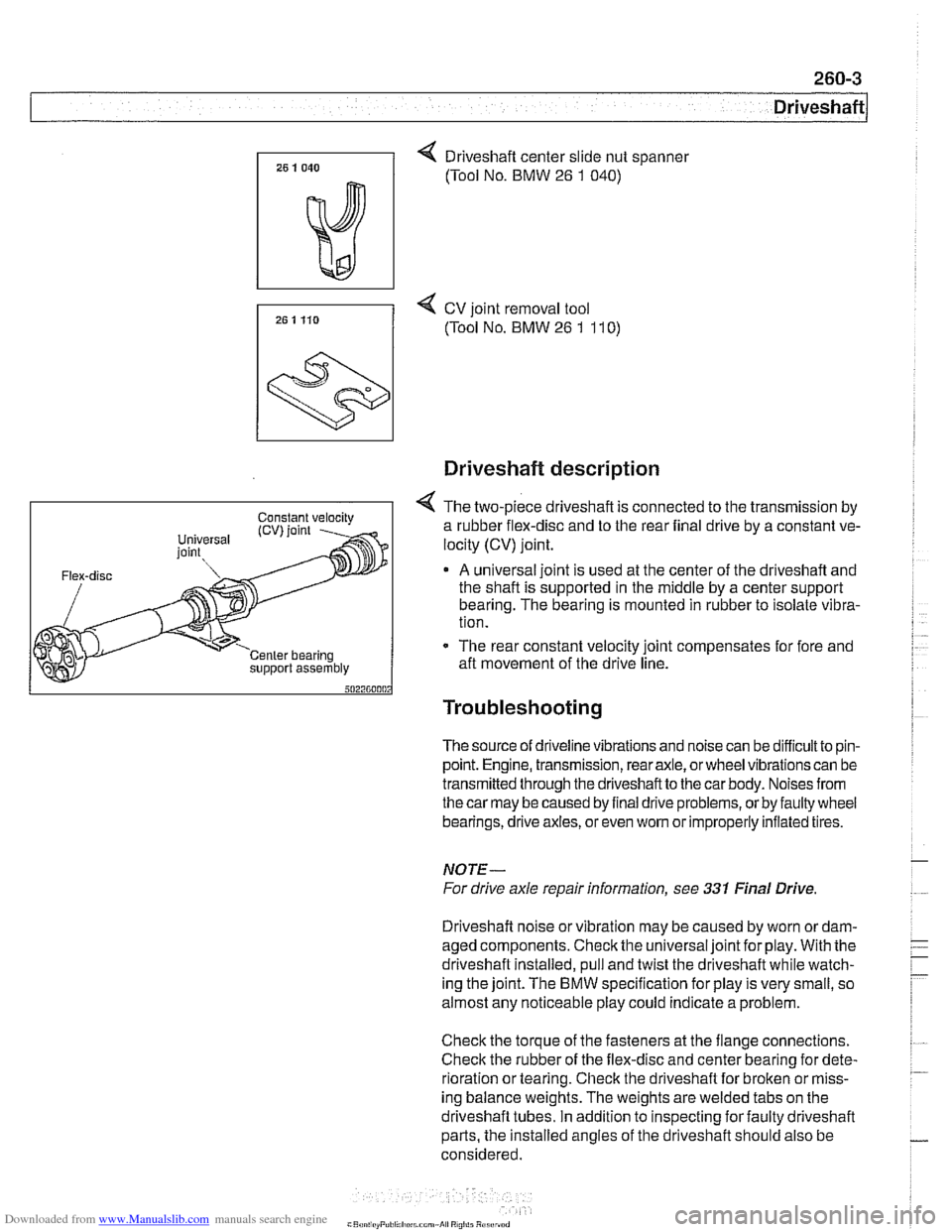
4 Driveshaft center slide nut spanner
(Tool No. BMW
26 1 040)
7, 25 1 Ho 4 cv joint removal tool
(Tool No. BMW 26 1 11 0)
support assembly
Driveshaft description
4 The two-piece driveshaft is connected to the transmission by
a rubber flex-disc and to the rear final drive by a constant ve-
locity (CV) joint.
A universal joint is used at the center of the driveshaft and
the shaft is supported in the middle by a center support
bearing. The bearing is mounted in rubber to isolate vibra-
tion.
- The rear constant velocity joint compensates for fore and
aft movement of the drive line.
Troubleshooting
The source of driveline vibrations and noise can be difficultto pin-
point. Engine, transmission, rear axle, or wheel vibrations can be
transmitted through thedriveshaftto the car body. Noises from
thecar may be caused by final drive problems, or by faulty wheel
bearings, drive axles, or even
wom or improperly inflated tires.
NOTE-
For drive axle repair information, see 331 Final Drive
Driveshaft noise or vibration may be caused by worn
ordam-
aged components. Check the universal joint for play. With the
driveshaft installed, pull and twist the driveshaft while watch-
ing the joint. The
BMW specification for play is very small, so
almost any noticeable play could indicate a problem.
Check the torque of the fasteners at the flange connections.
Check the rubber of the flex-disc and center bearing for dete-
rioration or tearing. Check the driveshaft for broken or miss-
ing balance weights. The weights are welded tabs on the
driveshaft tubes. In addition to inspecting for faulty driveshaft
parts, the installed angles of the driveshaft should also be
considered.
Page 610 of 1002
Downloaded from www.Manualslib.com manuals search engine
1 Driveshaft
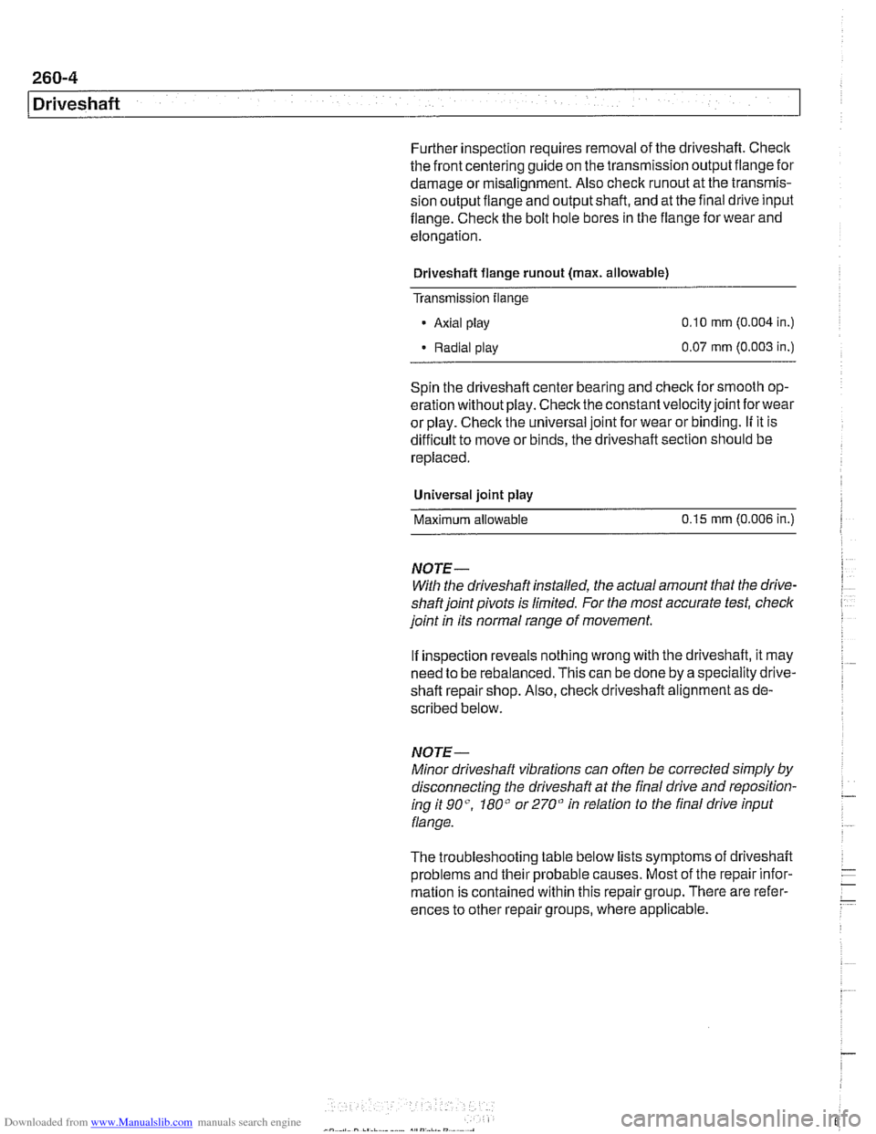
Further inspection requires removal of the driveshaft. Checlc
the front centering guide on the transmission output flange for
damage or
misalignment. Also check runout at the transmis-
sion output fiange and output shaft, and at the final drive input
fiange. Check the bolt hole bores in the flange for wear and
elongation.
Driveshaft flange
runout (max. allowable)
Transmission
flange
- Axial play 0.10 mm (0.004 in.)
Radial play 0.07
mm (0.003 in.)
Spin the driveshaft center bearing and
check ior smooth op-
eration without play. Check the constant velocity joint
forwear
or play. Checlc the universal joint for wear or binding. If it is
difficult to move or binds, the driveshaft section should be
replaced.
Universal joint
play
Maximum allowable 0.15
mm (0.006 in.)
NOTE-
With the driveshaft installed, the actual amount that the drive-
shaftjoint pivots is limited. For the most accurate test, check
joint
in its normal range of movement.
If inspection reveals nothing wrong with the driveshaft, it may
need to be rebalanced. This can be done by a speciality drive-
shaft repair shop. Also,
checlc driveshaft alignment as de-
scribed below.
NOTE-
Minor driveshaft vibrations can often be corrected simply by
disconnecting the driveshaft at the final drive and reposition-
ing it go", 180" or 270" in relation to the final drive input
flange.
The troubleshooting table below lists symptoms
oi driveshaft
problems and their probable causes. Most of the repair infor-
mation is contained within this repair group. There are refer-
ences to other repair groups, where applicable.
Page 705 of 1002
Downloaded from www.Manualslib.com manuals search engine
--
C. -- -- - -- Rear ~us~ensionl
Depending on year and model applications, the Sport Wagon
rear suspension may be equipped with:
Conventional shock absorbers and coil springs
Electronic height control (EHC) system which incorporates
air springs
NOTE-
. Suspension and EHC troubleshooting is covered in 300
Suspension, Steering and Brakes-General.
EHC system repairs, other than air spring replacement,
are covered in Electronic height control
(EHC) compo-
nent replacement.
Replace shock absorbers and springs in pairs only.
Rear shock absorber, removing and
installing
- Raise car and remove rear wheels,
WARNING-
Male sure that the car is firmly supported on jack stands de-
signed for the purpose. Place jack stands underneath struc-
tural chassis points. Do not place
jack stands under
suspension parts.
CAUTION-
If working on a vehicle with compressedairshock absorbers,
disable air supply pump by disconnecting electrical plug be-
fore performing any repairs. Pump is located beneath a cover
under the spare tire in the floor of the cargo compartment.
- Support swing arm from below
CAUTIOG
The shock absorber prevents the drive axle and wlieel bear-
ing carrier from dropping too far. Supporting the wheel bear-
ing carrier before disconnecting the shock absorber
mounting fasteners prevents damage to the
brake hose,
parking
brake cable and drive axle CVjoints.
- Working in cargo compartment, remove carpet. Remove tri-
angular upper shock mount covers located beside spare tire
well.
- If applicable: Detach air supply line from shock absorber.
Plug ports and lines to keep out dirt.