bolt BMW 528i 1999 E39 Workshop Manual
[x] Cancel search | Manufacturer: BMW, Model Year: 1999, Model line: 528i, Model: BMW 528i 1999 E39Pages: 1002
Page 386 of 1002
Downloaded from www.Manualslib.com manuals search engine
I Battery, Starter, Alternator
- Check for battery voltage at terminal 50 of starter motor with
key in start position. If voltage is not present, check wiring be-
tween ignition switch and starter terminal. Check the EWS
system and other inputs that disrupt terminal
56 to the start-
er. See ELE Electrical
Wiring Diagrams. If voltage is
present and no other visible wiring faults can be found, prob-
lem is most likely in starter motor.
Starter, removing and installing
(6-cylinder engine)
The starter is removed from below. Access to starter bolts is
difficult. Be sure to have the proper tools on hand before pro-
ceeding.
NOTE-
Access to the starter wiring is very limited. Forbetteraccess,
it may be necessary to remove the intake manifold.
- Disconnect negative (-) battery cable.
CAUTIOI\C
Prior to disconnecting the battern read the baltery discon-
nection cautions
in OOlGeneral Cautions and Warnings.
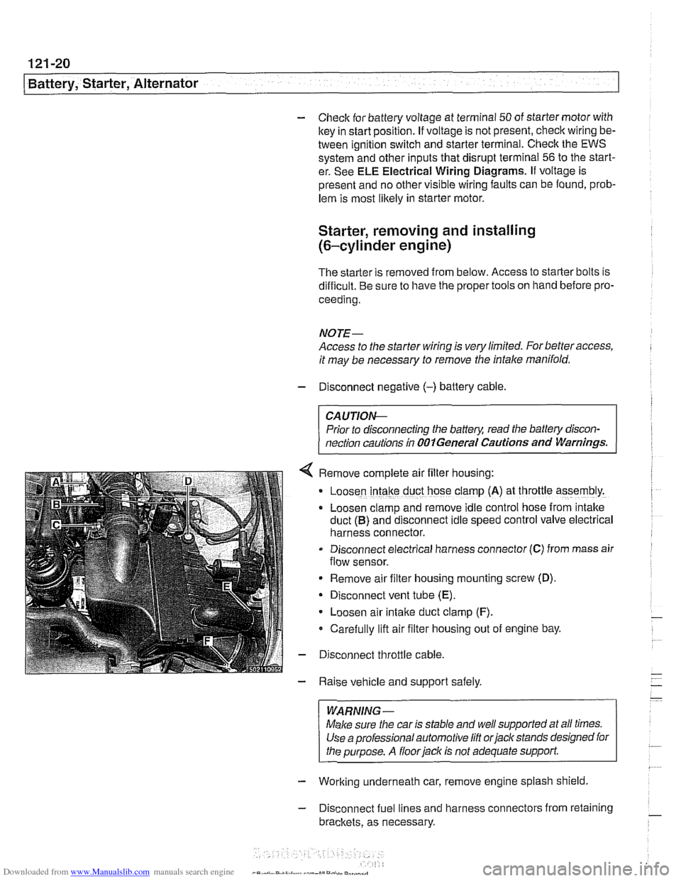
Remove complete air filter hous~ng:
Loosen intake duct hose clamp (A) at throttle assembly.
Loosen clamp and remove idle control hose from intake
duct
(B) and disconnect idle speed control valve electrical
harness connector.
Disconnect electrical harness connector
(C) from mass air
flow sensor.
Remove air filter housing mounting screw (D)
Disconnect vent tube
(E).
Loosen air intake duct clamp (F).
Carefully lift air filter housing out of engine bay.
Disconnect throttle cable.
Raise vehicle and support safely.
WARNING-
Make sure the car is stable and well supported at all times.
Use a professional automotive
lift orjack stands designed for
the purpose. A
floorjaclc is not adequate support
- Working underneath car, remove engine splash shield
- Disconnect fuel lines and harness connectors from retaining
brackets, as necessary.
Page 387 of 1002
Downloaded from www.Manualslib.com manuals search engine
Battery, Starter, ~lternatorl
- Disconnect wiring from starter.
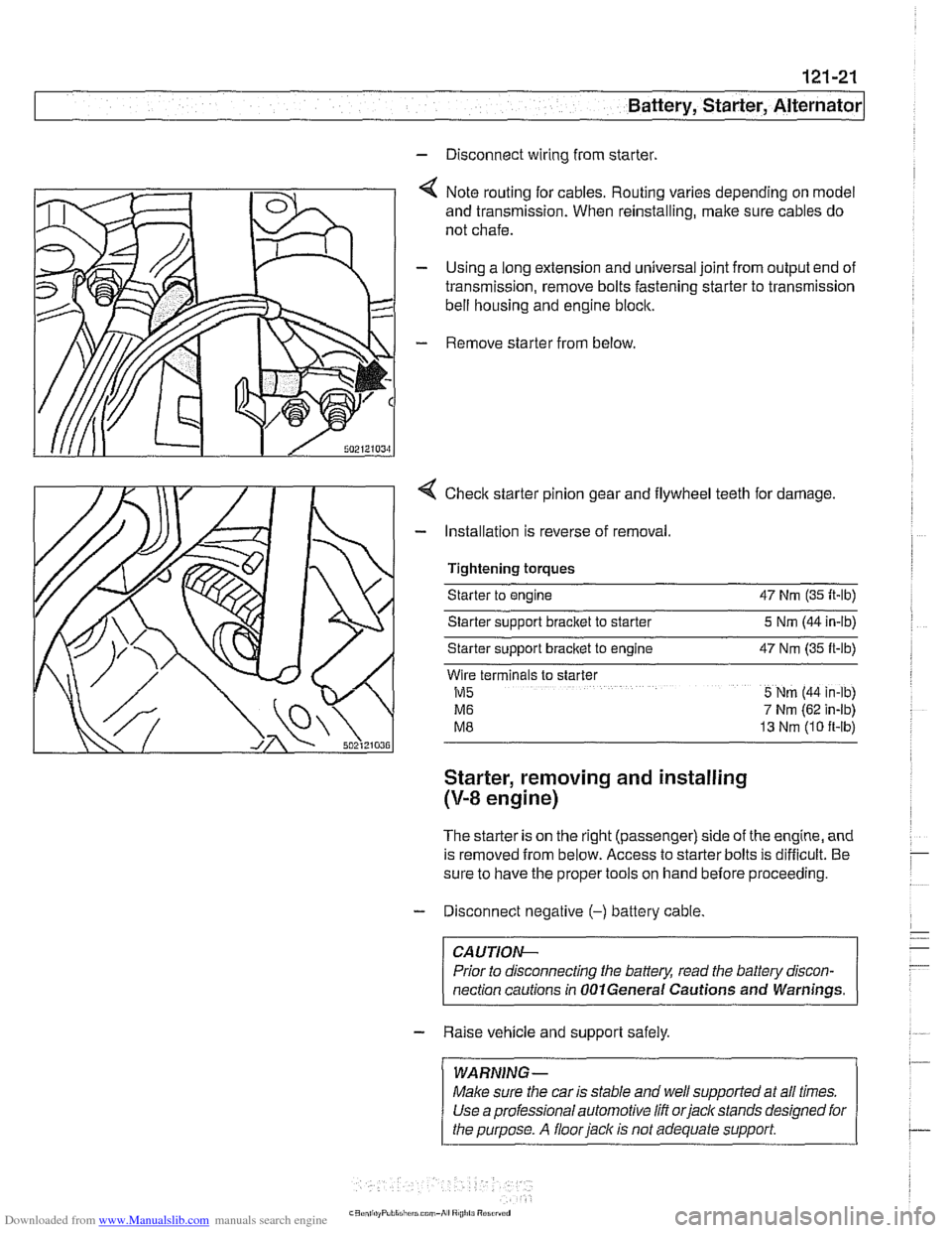
4 Note routing for cables. Routing varies depending on model
and transmission. When reinstalling, make sure cables do
not chafe.
- Using a long extension and universal joint from output end of
transmission, remove bolts fastening starter to transmission
bell housing and engine block.
- Remove starter from below
4 Checlc starter pinion gear and flywheel teeth for damage.
- Installation is reverse of removal.
Tightening torques
Starter to engine 47 Nrn (35 It-lb)
Starter sipport bracket to starter 5 Nrn (44 in-lb)
Starter support
bracket to engine 47 Nrn (35 ft-lb)
Wlre terminals to slarter
M5 5 Nrn (44 in-lb)
M6 7 Nrn (62 in-lb)
M8 13 Nrn (10 ft-lb)
Starter, removing and installing
(V-8 engine)
The starter is on the right (passenger) side of the engine, and
is removed from below. Access to starter bolts is difficult. Be
sure to have the proper tools on hand before proceeding.
- Disconnect negative (-) battery cable
CA UTIOW-
Prior to disconnecting the battery, read the battev discon-
nection cautions in
OOlGeneral Cautions and Warnings. -
- Raise vehicle and support safely.
/ WARNING- 1 ~ ~~ ~~ ~~~ ~
Make sure the car is stable and well supported at all times.
Use a professional automotive lift orjacltstands designed for
I the purpose. A floor jack is not adequate support I
Page 388 of 1002
Downloaded from www.Manualslib.com manuals search engine
-
Battery, Starter, Alternator
- Working underneath car, remove engine splash shield.
- Remove heat shield from starter.
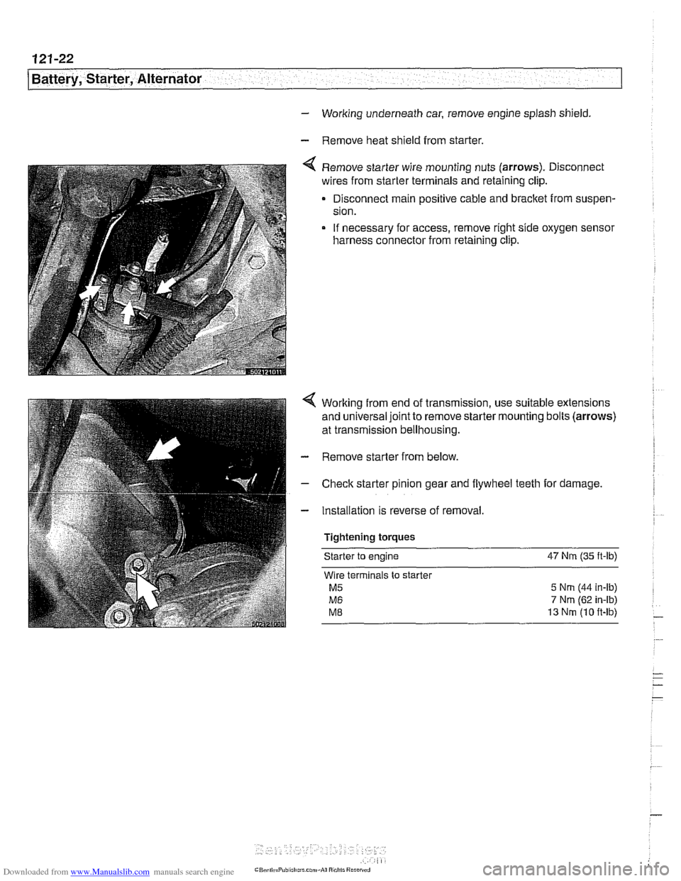
Remove starter wire mounting nuts (arrows). Disconnect
wires from starter terminals and retaining clip.
Disconnect main positive cable and bracket from suspen-
sion.
If necessary for access, remove right side oxygen sensor
harness connector from retaining clip.
Working from end of transmission, use suitable extensions
and universal joint to remove starter mounting bolts (arrows)
at transmission bellhousing.
- Remove starter from below.
- Check starter pinion gear and flywheel teeth for damage.
- Installation is reverse of removal
Tightening torques Starter
to engine 47 Nrn (35
ft-lb)
Wire terminals to starter
M5 5 Nrn (44 in-ib)
M6 7 Nm (62 in-ib)
ME 13 Nrn (10 ft-lb)
Page 402 of 1002
Downloaded from www.Manualslib.com manuals search engine
130-1 2
Fuel Injection
- Disconnect intake air boot from throttle housing. Unbolt throt-
tle housing and lay aside. It is not necessary to disconnect
throttle cable or electrical harness connectors from throttle housing.
- Remove electrical harness connector from IAT sensor.
- Unclip temperature sensor and remove from intake manifold.
- Installation is reverse of removal. Use a new gasket at throttle
housing.
Throttle position sensor (TPS),
testing and replacing
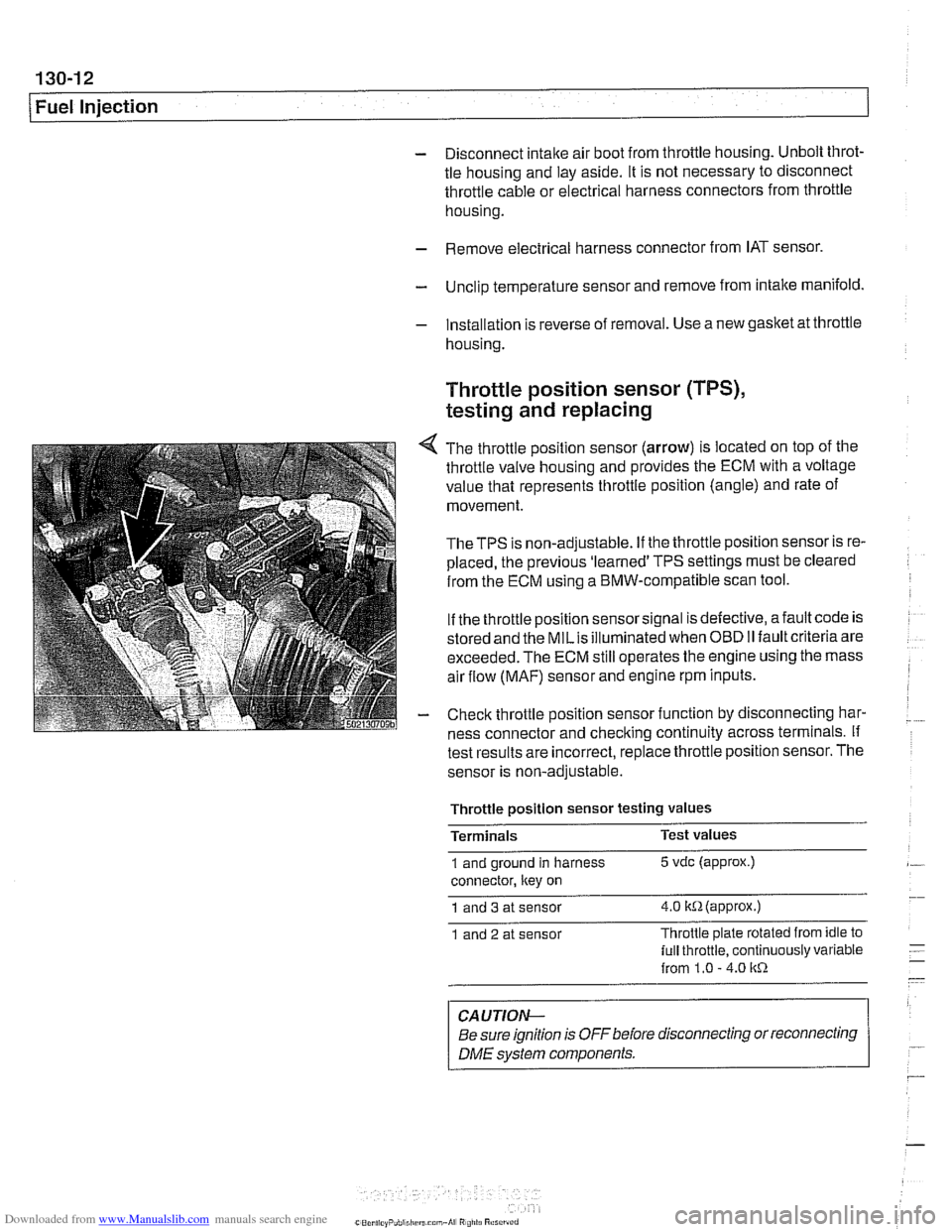
4 The throttle position sensor (arrow) is located on top of the
throttle valve housing and provides the ECM with a voltage
value that represents throttle position (angle) and rate of
movement.
TheTPS is non-adjustable. If the throttle position sensor is re-
placed, the previous 'learned' TPS settings must be cleared
from the ECM using a BMW-compatible scan tool.
If the throttle position sensor signal is defective, afault code is
stored and the
MILis illuminated when OBD II fault criteria are
exceeded. The ECM still operates the engine using the mass
air flow
(MAF) sensor and engine rpm inputs.
- Check throttle position sensor function by disconnecting har-
ness connector and checking continuity across terminals. If
test results are incorrect,
replace throttle position sensor. The
sensor is non-adjustable.
Throttle
~osition sensor testina values -
Terminals Test
values
1 and ground in harness 5 vdc (approx.)
connector, ltey on
1 and 3 at sensor 4.0 itR(appr0x.)
1 and 2 at sensor Throttle
plate rotated from idle to
lull throttle, continuously variable
from 1.0
- 4.0 1tR
CAUTION-
Be sure ignition is OFF before disconnecting or reconnecting
DME svstem components. r
Page 404 of 1002
Downloaded from www.Manualslib.com manuals search engine
Fuel Injection
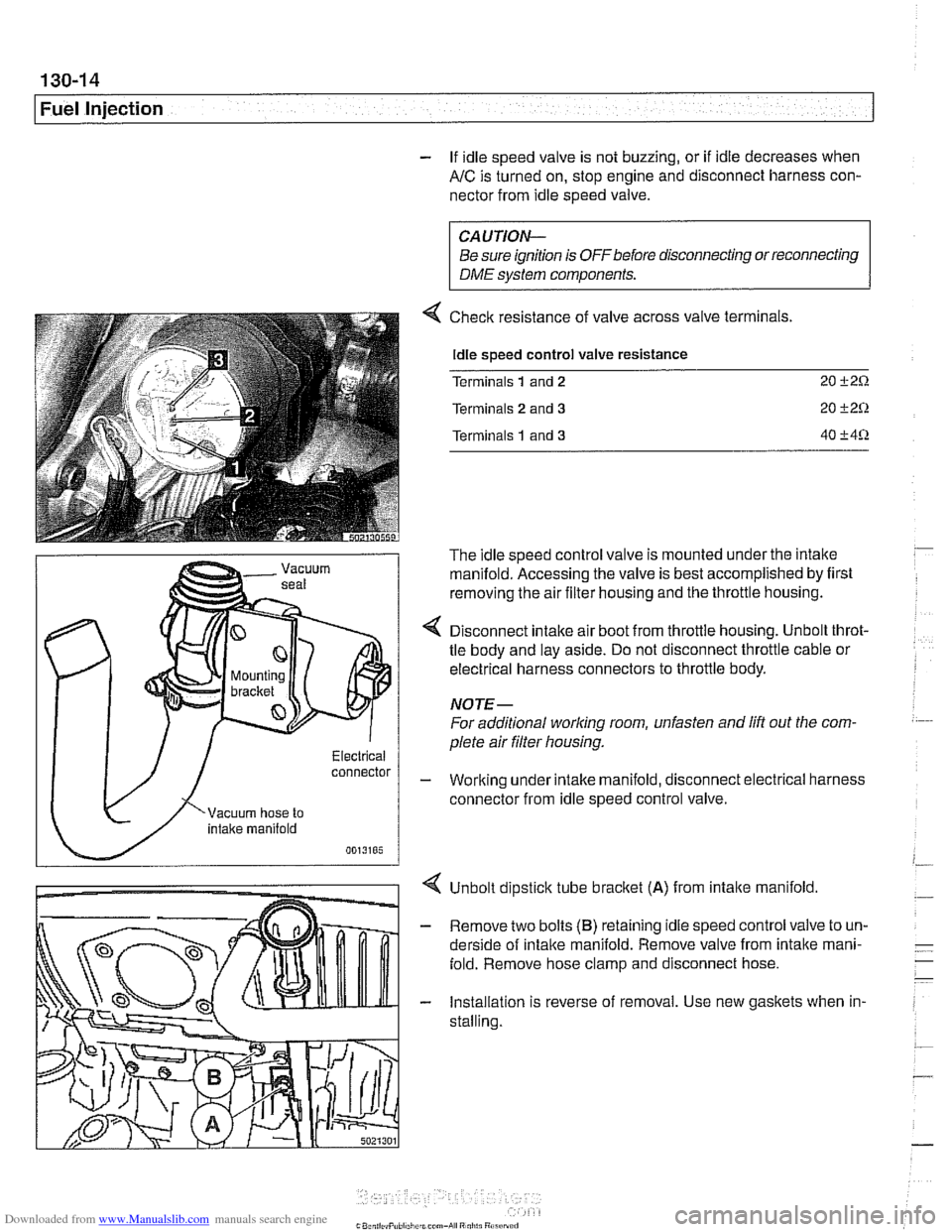
- If idle speed valve is not buzzing, or if idle decreases when
AIC is turned on, stop engine and disconnect harness con-
nector from idle speed valve.
connector
CAUTION-
Be sure ignition is OFFbefore disconnecting or reconnecting
DME system components.
Checlc resistance of valve across valve terminals.
Idle speed control valve resistance
Terminals
1 and 2 20 i-2Q
Terminals 2 and 3 20 C2Q
Terminals 1 and 3 40 C4Q
The idle speed control valve is mounted under the intake
manifold. Accessing the valve is best accomplished by first
removing the air filter housing and the throttle housing.
< Disconnect intake air boot from throttle housing. Unbolt throt-
tle body and lay aside. Do not disconnect throttle cable or
electrical harness connectors to throttle body.
NOTE-
For additional worlcing room, unfasten and lift out the com.
plete air filter housing.
- Working under intake manifold, disconnect electrical harness
connector from idle speed control valve.
Unbolt dipstick tube
bracket (A) from intalte manifold.
- Remove two bolts (B) retaining idle speed control valve to un-
derside of intalte manifold. Remove valve from intalte mani-
fold. Remove hose clamp and disconnect hose.
- Installation is reverse of removal. Use new gaskets when in-
stalling.
Page 423 of 1002
Downloaded from www.Manualslib.com manuals search engine
Fuel lniection I
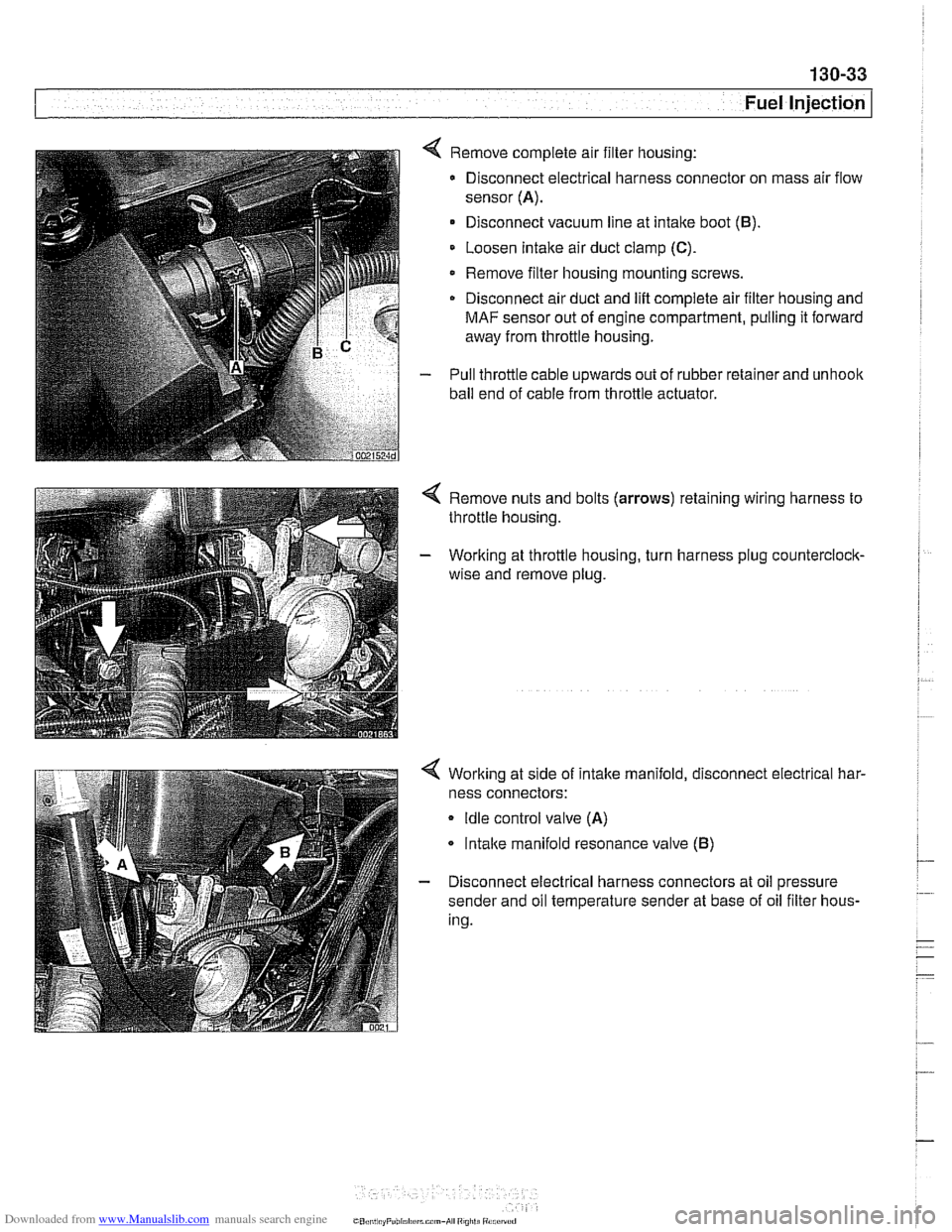
4 Remove complete air filter housing:
Disconnect electrical harness connector on mass air flow
sensor
(A).
Disconnect vacuum line at intake boot (B).
Loosen Intake air duct clamp (C).
Remove filter housing mounting screws
Disconnect air duct and
lift complete air filter housing and
MAF sensor out of engine compartment, pulling it forward
away from throttle housing.
- Pull throttle cable upwards out of rubber retainer and unhoolc
ball end of cable from throttle actuator.
4 Remove nuts and bolts (arrows) retaining wiring harness to
throttle housing.
- Working at throttle housing, turn harness plug counterclock-
wise and remove plug.
4 Working at side of intake manifold, disconnect electrical har-
ness connectors:
Idle control valve (A)
lntalce manifold resonance valve (B)
- Disconnect electrical harness connectors at oil pressure
sender and oil temperature sender at base of oil filter hous-
ing.
CO,l,> ti,, "F"bl,rl,irrm.,-AI ",",>ti
Page 424 of 1002
Downloaded from www.Manualslib.com manuals search engine
/Fuel Injection
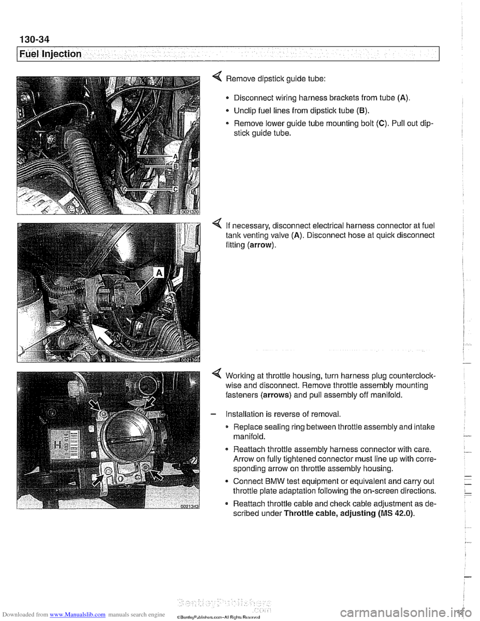
4 Remove dipstick guide tube:
Disconnect wiring harness brackets from tube (A).
Unclip fuel lines from dipstick tube
(El).
Remove lower guide tube mounting bolt (C). Pull out dip-
stick guide tube.
< If necessary, disconnect electrical harness connector at fuel
tank venting valve (A). Disconnect hose at quick disconnect
fitting (arrow).
Working at throttle housing, turn harness plug counterclock-
wise and disconnect. Remove throttle assembly mounting
fasteners (arrows) and pull assembly off manifold.
Installation is reverse of removal
Replace sealing ring between throttle assembly and intake
manifold.
0 Reattach throttle assembly harness connector with care.
Arrow on fully tightened connector must line up with corre-
sponding arrow on throttle assembly housing.
* Connect BMW test equipment or equivalent and carry out
throttle plate adaptation following the on-screen directions.
Reattach throttle cable and check cable adjustment as de-
scribed under Throttle cable, adjusting
(MS 42.0).
Page 426 of 1002
Downloaded from www.Manualslib.com manuals search engine
130-36
[~uel Injection
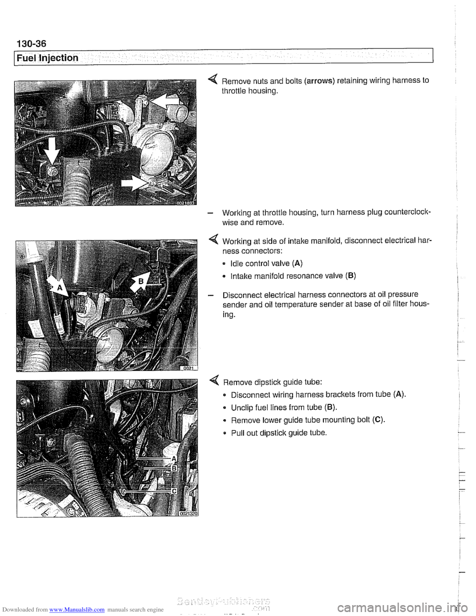
4 Remove nuts and bolts (arrows) retaining wiring harness to
throttle housing.
- Working at throttle housing, turn harness plug countercloclc
wise and remove.
4 Working at side of intake manifold, disconnect electrical bar-
ness connectors:
Idle control valve (A)
Intake manifold resonance valve (B)
- Disconnect electrical harness connectors at oil pressure
sender and oil temperature sender at base of oil filter hous-
ing.
4 Remove dipstick guide tube:
Disconnect wiring harness brackets from tube
(A)
Unclip fuel lines from tube (B).
Remove lower guide tube mounting bolt (C).
Pull out dipstick guide tube.
Page 429 of 1002
Downloaded from www.Manualslib.com manuals search engine
. .
Fuel Injection
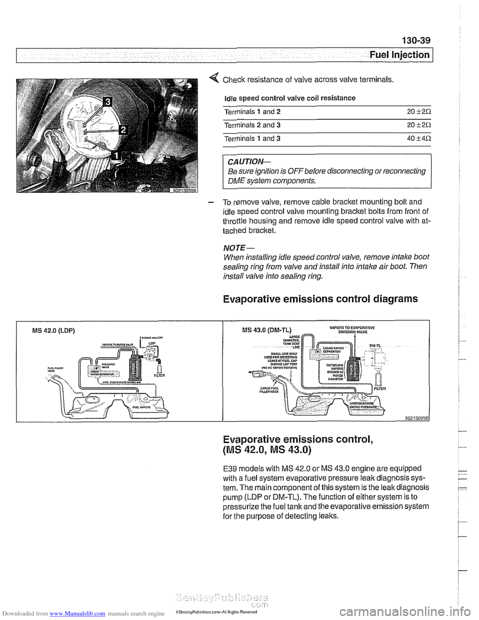
Check resistance of valve across valve terminals
Idle speed control valve coil resistance
Terminals
1 and 2 20 i2.0.
Terminals 2 and 3 20 i2.0.
Terminals 1 and 3 40 i4.0.
CAUTIOIG
Be sure ignition is OFFbefore disconnecting or reconnecting
DME system components.
- To remove valve, remove cable bracket mounting bolt and
idle speed control valve mounting bracket bolts from front of
throttle housing and remove idle speed control valve with at-
tached bracket.
NOTE-
When installing idle speed control valve, remove intake boot
sealing ring from valve and install into intake air boot. Then
install valve info sealing
ring.
Evaporative emissions control diagrams
MS 42.0 (LDP) ,-a"-
Evaporative emissions control,
(MS 42.0, MS 43.0)
E39 models with MS 42.0 or MS 43.0 engine are equipped
with a fuel system evaporative pressure leak diagnosis sys-
tem. The main component of this system is the leak diagnosis
pump (LDP or DM-TL). The function of either system is to
pressurize the fuel tank and the evaporative emission system
for the purpose of detecting leaks.
Page 443 of 1002
Downloaded from www.Manualslib.com manuals search engine
Fuel Injection I
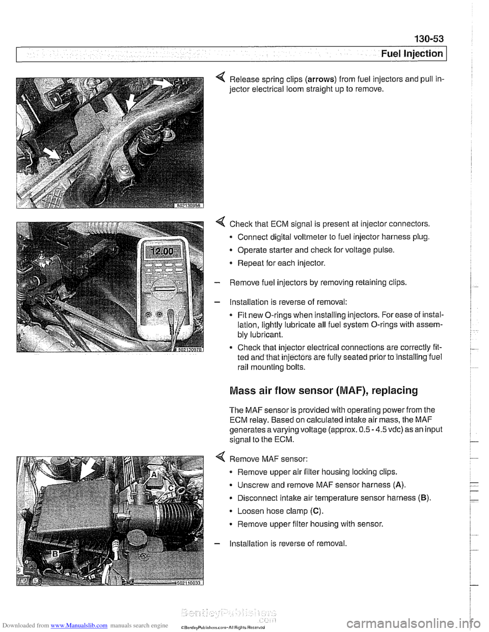
4 Release spring clips (arrows) from fuel injectors and pull in-
jector electrical loom straight up to remove.
4 Check that ECM signal is present at injector connectors.
- Connect digital voltmeter to fuel injector harness plug.
Operate starter and
check for voltage pulse.
* Repeat for each injector.
- Remove fuel injectors by removing retaining clips
- Installation is reverse of removal:
Fit new O-rings when installing injectors. For ease of instal-
lation, lightly lubricate all fuel system O-rings with assem-
bly lubricant.
Check that injector electrical connections are correctly fit-
ted and that
injectors are fully seated prior to installing iuel
rail mounting bolts.
Mass air flow sensor (MAF), replacing
The MAF sensor is provided with operating power from the
ECM relay. Based on calculated intake air mass, the MAF
generates
avarying voltage (approx. 0.5 - 4.5 vdc) as an input
signal to the ECM.
4 Remove MAF sensor:
Remove upper air filter housing locking clips.
Unscrew and remove MAF sensor harness
(A).
Disconnect intake air temperature sensor harness (B).
Loosen hose clamp (C).
Remove upper filter housing with sensor.
- Installation is reverse of removal