bolt BMW 528i 1999 E39 Workshop Manual
[x] Cancel search | Manufacturer: BMW, Model Year: 1999, Model line: 528i, Model: BMW 528i 1999 E39Pages: 1002
Page 447 of 1002
Downloaded from www.Manualslib.com manuals search engine
Fuel Injection
Intake air temperature
([AT) sensor,
testing and replacing
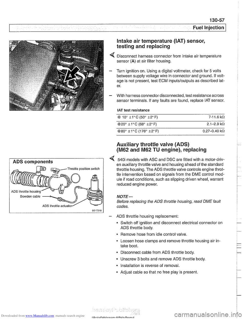
Disconnect harness connector from intake air temperature
sensor
(A) at air filter housing.
Turn ignition on. Using a digital voltmeter, check for
5 volts
between supply voltage wire in connector and ground.
If volt-
age is not present, test ECM
inputs/outputs as described lat-
er.
With harness connector disconnected, test resistance across
sensor terminals. If any faults are found, replace IAT sensor.
IAT test resistance
0 lV *lac (50" i-2°F) 7-1 1.6 k.0.
020' kl°C (68' 322°F) 2.1-2.9 it.0.
080" ?lac (176" i-2°F) 0.27-0.40 itn
Auxiliary throttle valve (ADS)
(M62 and M62 TU engine), replacing
ADS components 540i models with ASC and DSC are fitted with a motor-driv-
en auxiliary throttle valve and housing ahead of the standard Throttle position switch throttle housing. The ADS throttle valve controls engine throt-
tle intervention based on signals from the DME control mod-
ule if road conditions, such as slipping driven wheel, warrant
reduced engine power.
ADS throttle housing
Bowden cable NOTE-
Before replacing the ADS throttle housing, read DME fault
ADS lhroltle actualor codes.
- ADS throttle housing replacement:
Switch off ignition and disconnect electrical connector on
ADS throttle body.
Remove hose from idle control valve.
Loosen hose clamps and remove throttle housing air in-
take boot.
Disconnect cable from ADS throttle body.
- Unscrew 3 bolts and remove ADS throttle body.
Installation is reverse of removal.
- Adjust cable so that no free play is present.
Page 492 of 1002
Downloaded from www.Manualslib.com manuals search engine
160-22
Fuel Tank and Fuel Pump
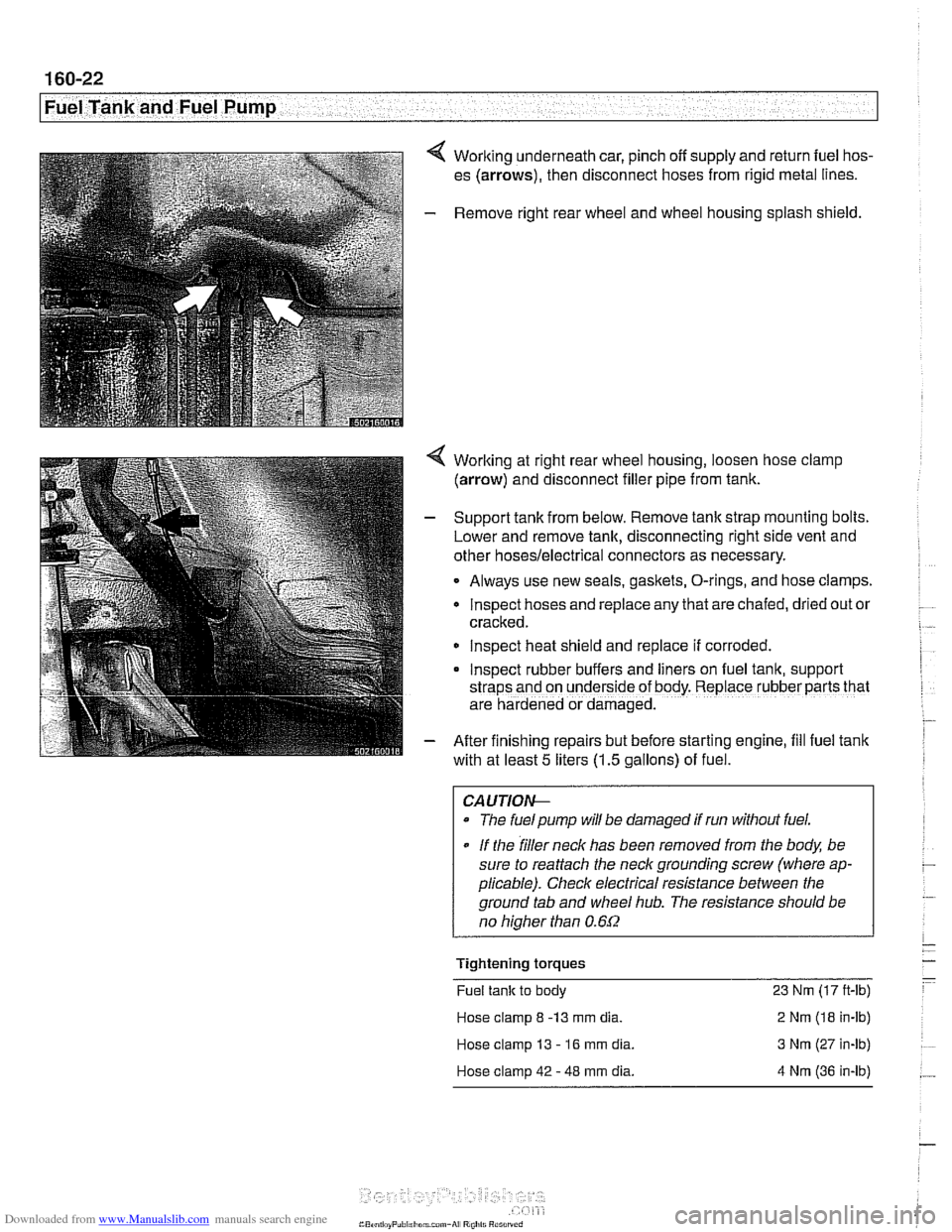
4 Working underneath car, pinch off supply and return fuel hos-
es (arrows), then disconnect hoses from rigid metal lines.
- Remove right rear wheel and wheel housing splash shield.
4 Worlting at right rear wheel housing, loosen hose clamp
(arrow) and disconnect filler pipe from tank.
- Support tank from below. Remove tank strap mounting bolts.
Lower and remove tank, disconnecting right side vent and
other
hoses/electrical connectors as necessary.
Always use new seals, gaskets, O-rings, and hose clamps.
lnspect hoses and replace any that are chafed,
dr~ed out or
cracked.
lnspect heat shield and replace if corroded.
Inspect rubber buffers and
hers on fuel tank, support
straps and on underside of body. Replace rubber parts that
are hardened or damaged.
- After finishing repairs but before starting engine, fill fuel tank
with at least
5 liters (1.5 gallons) of fuel.
CAUTlOI+
The fuelpump will be damaged if run without fuel.
* If the filler neck has been removed from the body, be
sure to reattach the
neck grounding screw (where ap-
plicable). Check electrical resistance between the
ground tab and wheel
hub. The resistance should be
no
hiaher than 0.6f2
Tightening torques
Fuel tank to body 23 Nm (17 ft-lb)
Hose clamp
8 -13 mm dia. 2 Nm (18 in-lb)
Hose clamp 13
- 16 mm dia. 3 Nm (27 in-lb)
Hose clamp 42
- 48 mm dia. 4 Nm (36 in-lb)
Page 511 of 1002
Downloaded from www.Manualslib.com manuals search engine
Radiator and Cooling System
Remove rubber trim strip between top of shroud and radiator.
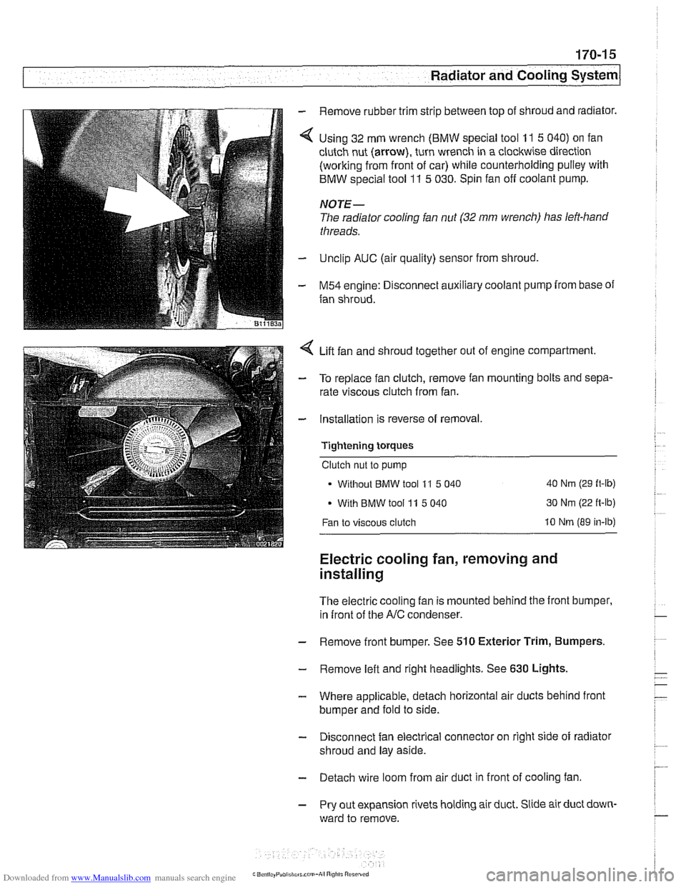
Using 32 mm wrench
(BMW special tool 11 5 040) on fan
clutch nut (arrow), turn wrench in a clockwise direction
(working from front of car) while counterholding pulley with
BMW special tool
11 5 030. Spin fan off coolant pump.
NOTE-
The radiator cooling fan nut (32 mm wrench) has left-hand
threads.
Unclip AUC (air quality) sensor from shroud,
M54 engine: Disconnect auxiliary coolant pump from base of
fan shroud.
Lift fan and shroud together out of engine compartment.
To replace fan clutch, remove fan mounting bolts and sepa-
rate viscous clutch from fan.
Installation is reverse of removal.
Tightening
torques
Clutch nut to pump
Without
BMW tool 11 5 040 40 Nm (29 ft-lb)
With BMW tool 11 5 040 30 Nm
(22 ft-lb)
Fan to viscous clutch 10 Nm (89 in-lb)
Electric cooling fan, removing and
installing
The electric cooling fan is mounted behind the front bumper,
in front of the
A/C condenser.
- Remove front bumper. See 510 Exterior Trim, Bumpers.
- Remove left and right headlights. See 630 Lights,
- Where applicable, detach horizontal air ducts behind front
bumper and fold to side.
- Disconnect fan electrical connector on right side of radiator
shroud and lay aside.
- Detach wire loom from air duct in front of cooling fan
- Pry out expansion rivets holding air duct. Slide air duct down-
ward to remove.
Page 512 of 1002
Downloaded from www.Manualslib.com manuals search engine
170-1 6
I Radiator and Cooling System
- Remove fan and fan shroud mounting fasteners. Slide fan
and fan shroud downward to remove.
- Reinstallation is reverse of removal.
Thermostat, removing and installing
(M52 engine)
The coolant thermostat is installed in a housing at the front of
the engine.
- Drain coolant from radiator and engine block. See Coolant,
draining and filling (6-cylinder models).
WARNING -
Allow the cooling system to cool before opening or draining
the system.
- Remove mechanical cooling fan and fan shroud. See Me-
chanical (viscous clutch) cooling fan, removing and in-
stalling.
- Disconnect coolant hoses from thermostat housing.
- Remove thermostat housing from front of engine.
- Remove thermostat. Note thermostat direction and orienta-
tion before removing.
- Installation is reverse of removal, noting the following:
- Use new O-ring and gasket(s) when installing thermostat
and housing.
NOTE-
Some thermostats have a direction arrow or vent hole near
the edge. Install the thermostat so that either the arrow or
hole are at the top.
Fill system with coolant as described in Coolant, draining
and filling (6-cylinder models).
CAUTION-
Be sure to reconnect ground wire@) at thermostat housing
mounting bolt, where applicable.
Page 513 of 1002
Downloaded from www.Manualslib.com manuals search engine
Radiator and Cooling systeml
Tightening torques
Block drain plug to block 25 Nm
(18
it-lb)
Coolant hose clamp (32 - 48 2.
5 Nm (22 in-lb)
mm hose diameter)
Radiator drain plug to radiator
2-3Nm(l8-27in-lb)
Thermostat housing to cylinder
head 10 Nm (89 in-lb)
I Coolant thermostat housing assmbly- - I
Thermostat, removing and installing
(M52 TU or M54 engine)
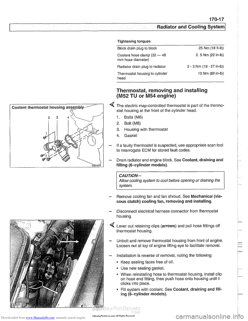
4 The electric map-controlled thermostat is part of the thermo-
stat housing at the front of the cylinder head.
1. Bolts (M6)
2 Bolt (ME)
3. Housing with thermostat
4. Gasket
- If a faulty thermostat is suspected, use appropriate scan tool
to interrogate
ECM for stored fault codes.
- Drain radiator and engine block. See Coolant, draining and
filling (6-cylinder models).
CAUTION-
Allow cooling system to cool before opening or draining the
system.
- Remove cooling fan and fan shroud. See Mechanical (vis-
cous clutch) cooling fan, removing and installing.
- Disconnect electrical harness connector from thermostat
housina.
4 Lever out retaining clips (arrows) and pull hose fittings off
thermostat housing.
- Unbolt and remove thermostat housing from front of engine.
Loosen nut at top of engine lifting eye to facilitate removal.
- Installation is reverse of removal, noting the following:
Keep sealing faces free of oil.
* Use new sealing gasket.
When reinstalling hose to thermostat housing, install clip
on hose end fitting, then push hose onto housing until it
clicks into place.
Fill system with coolant. See Coolant, draining and fill-
ing (6-cylinder models).
Page 515 of 1002
Downloaded from www.Manualslib.com manuals search engine
170-1 9
Radiator and Cooling System
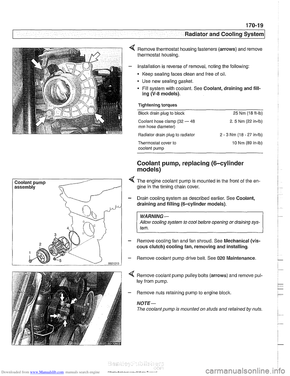
Coolant pump Remove thermostat housing fasteners
(arrows) and remove
thermostat housing.
Installation is reverse of removal, noting the following:
- Keep sealing faces clean and free of oil.
Use new sealing gasket.
Fill system with coolant. See Coolant, draining and fill-
ing
(V-8 models).
Tightening torques
Block drain plug to block 25 Nm (18 it-lb)
Coolant hose clamp (32
- 48 2. 5 Nm (22 in-lb)
mm hose diameter)
Radiator drain plug to radiator 2
- 3 Nm (18 - 27 In-lb)
Thermostat cover to
coolant pump 10 Nm (89 in-lb)
Coolant pump, replacing (6-cylinder
models)
< The engine coolant pump is mounted in the front of the en-
gine in the timing chain cover.
- Drain cooling system as described earlier. See Coolant,
draining and filling (6-cylinder models).
WARNING-
Allow cooling system to cool before opening or draining sys-
tem.
- Remove cooling fan and fan shroud. See Mechanical (vis-
cous clutch) cooling fan, removing and installing.
- Remove coolant pump drive belt. See 020 Maintenance.
4 Remove coolant pump pulley bolts (arrows) and remove pul-
ley from pump.
- Remove nuts retaining pump to engine block.
NOTE-
The coolant pump is mounted on studs and retained by nuts.
Page 517 of 1002
Downloaded from www.Manualslib.com manuals search engine
Radiator and Coolina ~vsteml
- Disconnect thermostat and cooling system temperature sen-
sor plug connectors.
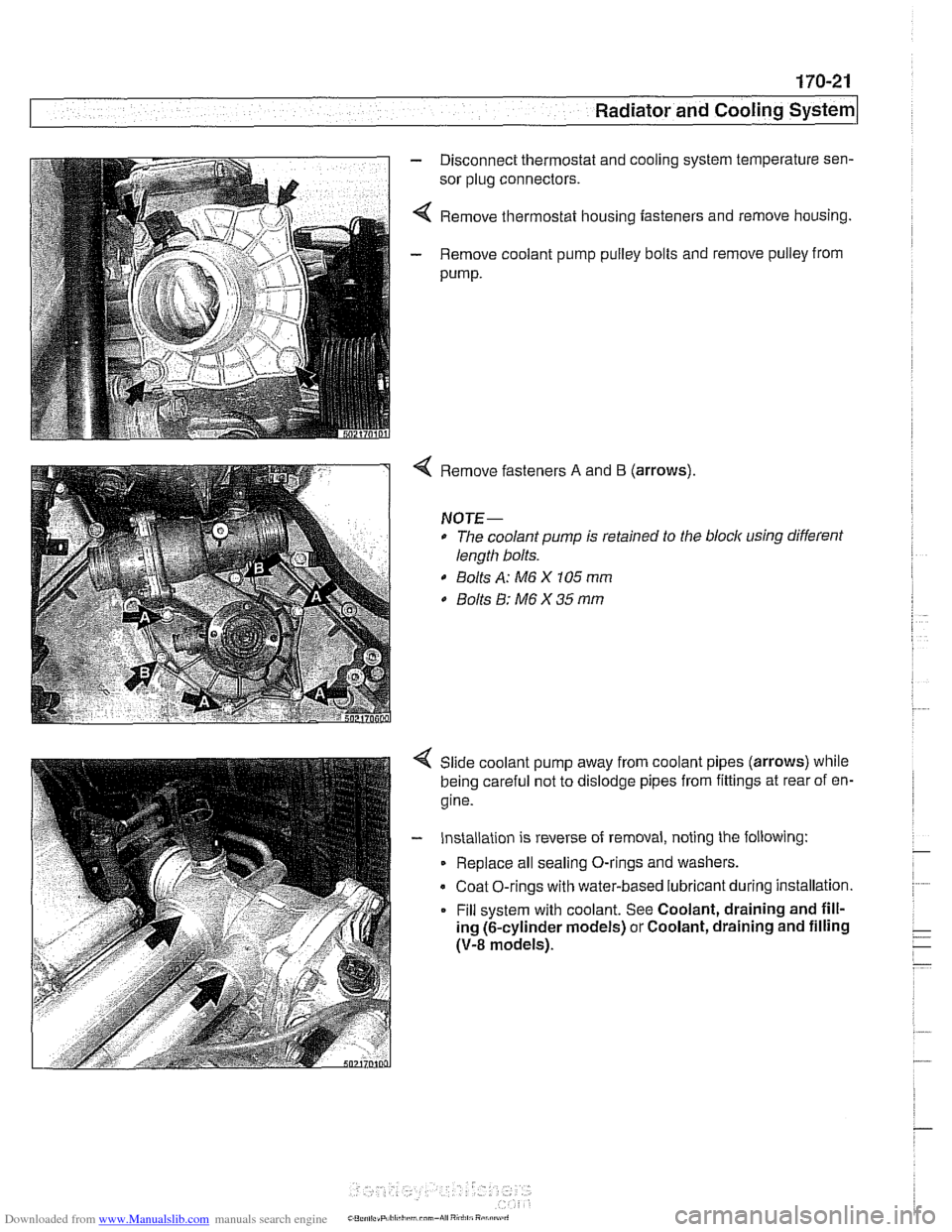
4 Remove thermostat housing fasteners and remove housing.
- Remove coolant pump pulley bolts and remove pulley from
pump.
Remove fasteners A and B (arrows).
NOTE-
* The coolant pump is retained to the block using different
length bolts.
0 Bolts A: M6 X 105 mm
0 Bolts 8: M6 X 35 mm
Slide coolant pump away from coolant pipes (arrows) while
being careful not to dislodge pipes from fittings at rear of en-
gine.
- Installation is reverse of removal, noting the following:
Replace all sealing O-rings and washers.
Coat O-rings with water-based lubricant during installation.
Fill system with coolant. See Coolant, draining and fill-
ing (6-cylinder models) or Coolant, draining and filling
(V-8 models).
Page 520 of 1002
Downloaded from www.Manualslib.com manuals search engine
--
Radiator and Cooling System 1
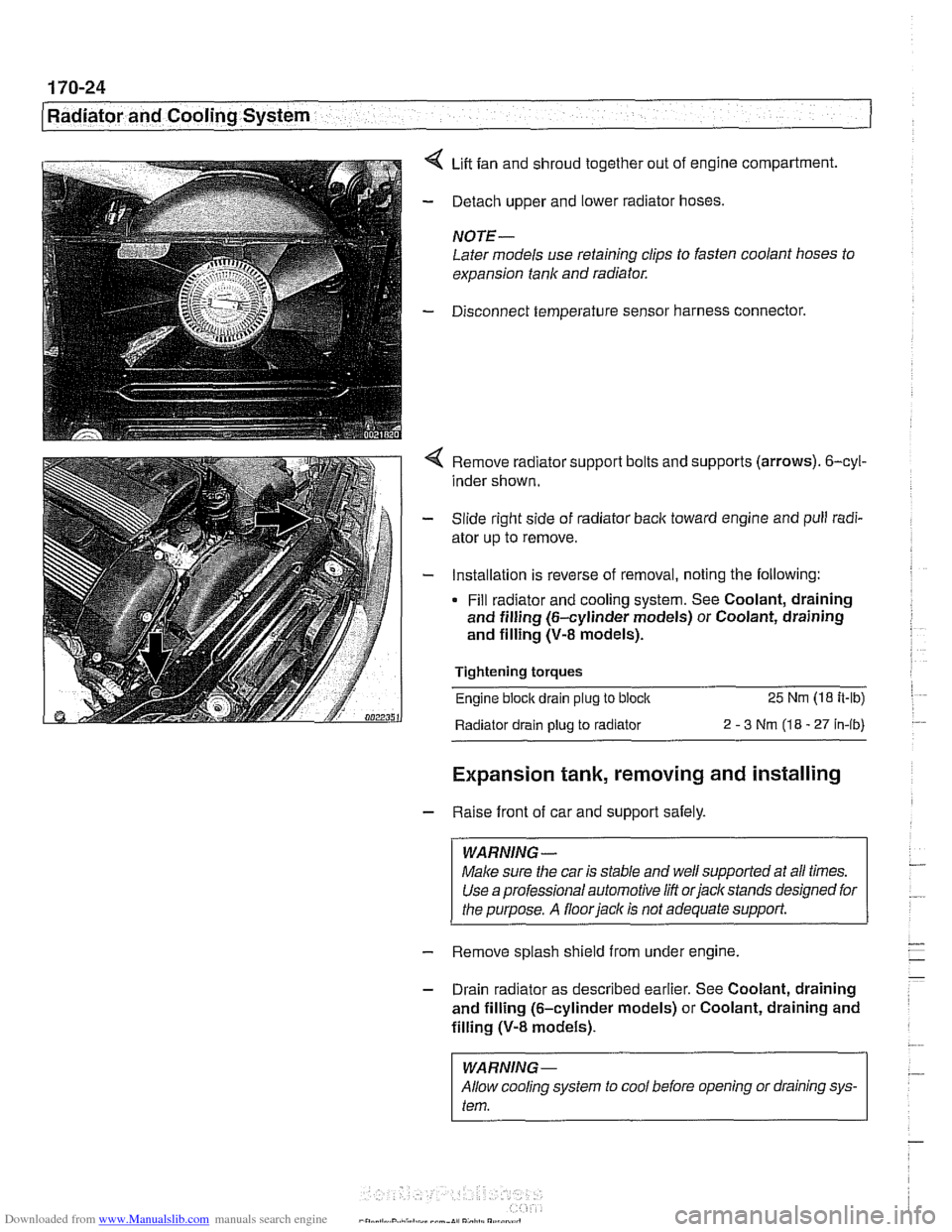
4 Lift fan and shroud together out of engine compartment.
- Detach upper and lower radiator hoses.
NOTE -
Later models use retaining clips to fasten coolant hoses to
expansion tank and radiator.
- Disconnect temperature sensor harness connector.
4 Remove radiator support bolts and supports (arrows). 6-cyl-
inder shown.
- Slide right side of radiator back toward engine and pull radi-
ator up to remove.
- Installation is reverse of removal, noting the following:
Fill radiator and cooling system. See Coolant, draining
and filling (6-cylinder models) or Coolant, draining
and filling (V-8 models).
Tightening torques
Engine block drain
plug to block 25 Nm (18 it-lb)
Radiator drain plug
to radiator 2 - 3 Nm (18 - 27 in-ib)
Expansion tank, removing and installing
- Raise front of car and support safely.
WARNING -
Make sure the car is stable and well supported at all times.
Use a professional automotive
/iff orjacltstands designed for
the purpose. A
floorjacl~ is not adequate support.
- Remove splash shield from under engine.
- Drain radiator as described earlier. See Coolant, draining
and filling (6-cylinder models) or Coolant, draining and
filling
(V-8 models).
I WARNING-
Allow cooling system to cool before opening or draining sys-
I tem.
Page 524 of 1002
Downloaded from www.Manualslib.com manuals search engine
180-2
Exhaust System
The exhaust system is designed to be maintenance free, al-
though regular inspection is warranted due to the harsh oper-
ating conditions. Under normal conditions, the catalytic
converter does not require replacement unless it is damaged.
New fasteners, clamps, rubber mounts and gaskets should
be used when replacing exhaust components.
A liberal appli-
cation of penetrating oil to the exhaust system nuts and bolts
in advance may make removal easier.
WARNING -
The exhaust system and catalytic converter operate at
very high temperatures. Allow components to cool before
servicing. Wear protective clothing to prevent burns.
Do not use flammable chemicals near a hot
cataiyiic
converter.
Corroded exhaust system components crumble easily
and often have exposed sharp edges. To avoid injury,
wear eye protection and heavy gloves when working
Exhaust system, removing and installing
The removal and installation procedures given here are gen-
eral procedures for all models. The removal of the exhaust
system as a complete unit is recommended. Once the com-
plete system is removed from the car, individual pipes and
mufflers can be more easily replaced.
WARNING-
Exhaust gases are colorless, odorless, and very toxic. Run
the engine only in a well-ventilated area. Immediately repair
any
leaks in the exhaust system or structural damage to the
car body that
might allow exhaust gases to enter the passen-
ger compartment.
CAUTION-
Use care not to drag or bang oxygen sensors. Oxygen sen-
sors can be easily ruined.
Page 525 of 1002
Downloaded from www.Manualslib.com manuals search engine
... .
Exhaust System
- With exhaust system fully cold, raise and support car for ac-
cess to exhaust system.
WARNING -
Do not worlc under a lifted car unless it is solidly supported on
jack stands designed for that purpose. Never work under a
car that is supported solely by a
jack.
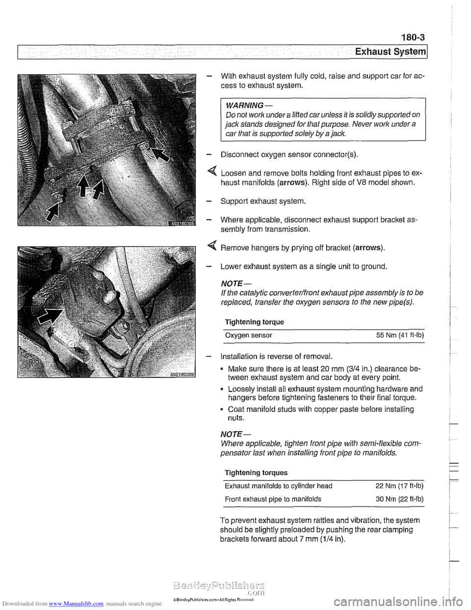
- Disconnect oxygen sensor connector(s).
4 Loosen and remove bolts holding front exhaust pipes to ex-
haust manifolds (arrows). Right side of
V8 model shown.
- Support exhaust system
- Where applicable, disconnect exhaust support bracket as-
sembly from transmission.
< Remove hangers by prying off bracket (arrows).
- Lower exhaust system as a single unit to ground.
NOTE-
If the catalytic converterlfront exhaust pipe assembly is to be
replaced, transfer the oxygen sensors to the new
pipe(s).
Tightening torque
Oxygen sensor
55 Nm (41 ft-lb)
- installation is reverse of removal.
* Make sure there is at least 20 mm (314 in.) clearance be-
tween exhaust system and car body at every point.
Loosely install
ail exhaust system mounting hardware and
hangers before tightening fasteners to their final torque.
Coat manifold studs with copper paste before installing
nuts.
NOTE-
Where applicable, tighten front pipe with semi-flexible com-
pensator last when installing front pipe to
manifolds.
Tightening torques
Exhaust manifolds
to cylinder head 22 Nm (1 7 It-lb)
Front exhaust pipe to manifolds 30 Nm (22 ft-lb)
To prevent exhaust system rattles and vibration, the system
should be slightly preloaded by pushing the rear clamping
brackets forward about 7 mm (114 in).