bolt BMW 528i 1999 E39 Workshop Manual
[x] Cancel search | Manufacturer: BMW, Model Year: 1999, Model line: 528i, Model: BMW 528i 1999 E39Pages: 1002
Page 343 of 1002
Downloaded from www.Manualslib.com manuals search engine
Lubrication System
- Lower front suspension and remove oil pan, as described
earlier, to gain access to oil pump.
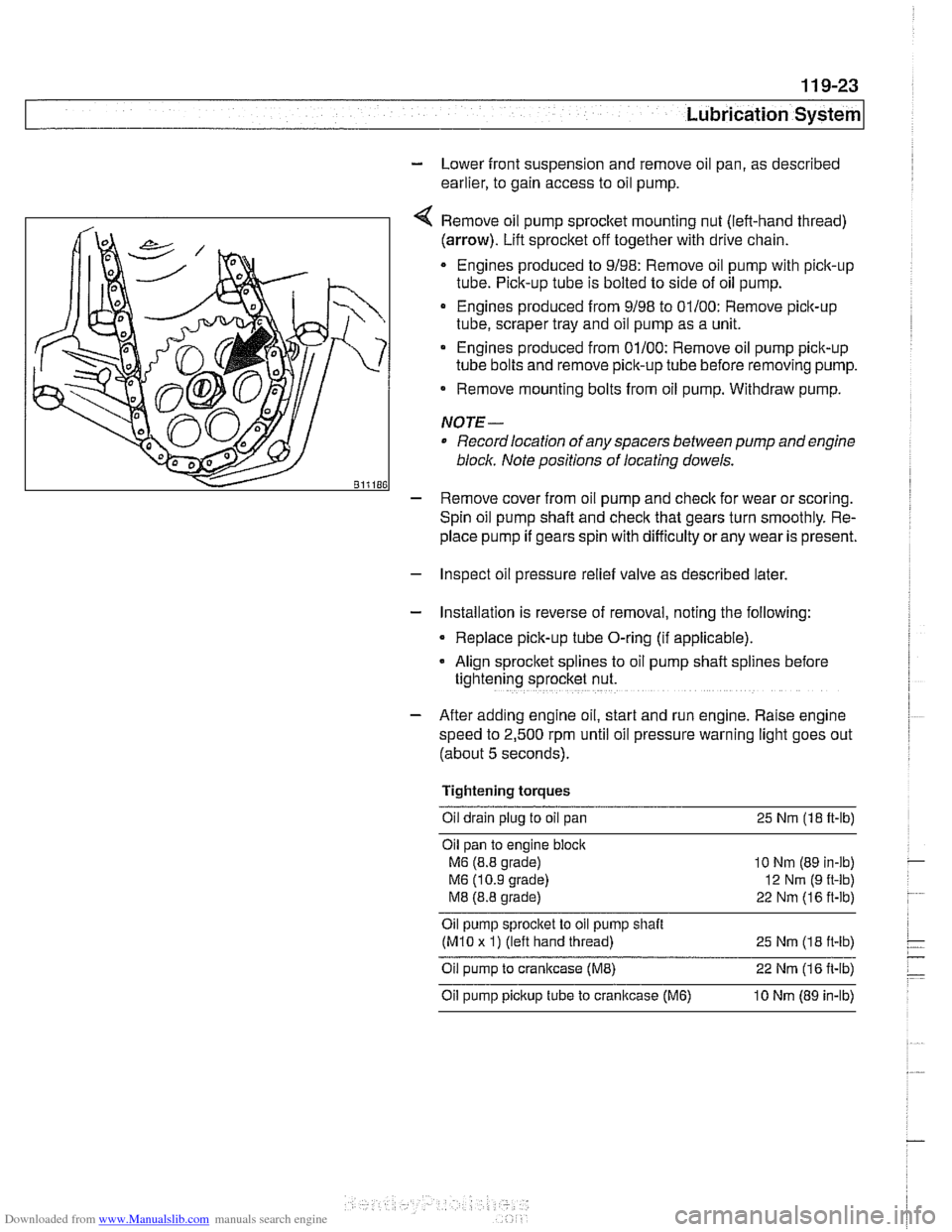
Remove oil pump
sprocket mounting nut (left-hand thread)
(arrow). Lift sprocket off together with drive chain.
Engines produced to 9/98: Remove oil pump with pick-up
tube. Pick-up tube is bolted to side of oil pump.
Engines produced from 9/98 to 01/00: Remove pick-up
tube, scraper tray and oil pump as a unit.
Engines produced from 01/00: Remove oil pump pick-up
tube bolts and remove pick-up tube before removing pump.
Remove mounting bolts from oil pump. Withdraw pump.
NOTE-
Record location of any spacers between pump and engine
bloclc Note positions of locating dowels.
- Remove cover from oil pump and check for wear or scoring.
Spin oil pump shaft and
check that gears turn smoothly. Re-
place pump if gears spin with difficulty
orany wear is present.
- Inspect oil pressure relief valve as described later.
- Installation is reverse of removal, noting the following:
Replace pick-up tube O-ring (if applicable).
- Align sprocket splines to oil pump shaft spl~nes before
tightening sprocket nut.
- After adding engine oil, start and run engine. Raise engine
speed to 2,500 rpm until oil pressure warning light goes out
(about 5 seconds).
Tightening torques Oil drain plug to oil pan 25
Nm (18 ft-lb)
Oil pan to engine
bloclc
M6 (8.8 grade)
M6 (10.9 grade)
M8 (8.8 grade)
10 Nm (89 in-lb)
12
Nrn (9 ft-lb)
22 Nm (16 ft-lb)
Oil pump sprocket to oil pump shait
(M10 x 1) (left hand thread)
25 Nm (1 8 it-lb)
Oil pump to crankcase (ME) 22 Nm (1 6 it-lb)
Oil pump pickup tube to cranltcase (M6) 10 Nm (89 in-lb)
Page 344 of 1002
Downloaded from www.Manualslib.com manuals search engine
11 9-24
Lubrication System
Oil pump, removing and installing (V-8)
CAUTION-
V8 engines: The oil pump fasteners (including the sprocket
retaining nut) are known to vibrate loose. This can result in oil
starvation and engine failure. Be sure to
checlc oil bolts and
nut tighness whenever the oil pump is accessible. If any fas-
teners are found to be loose, remove them and reinstall with
Loctite
8 and torque to specifications.
- Remove upper oil pan, as described earlier, to gain access to
oil pump.
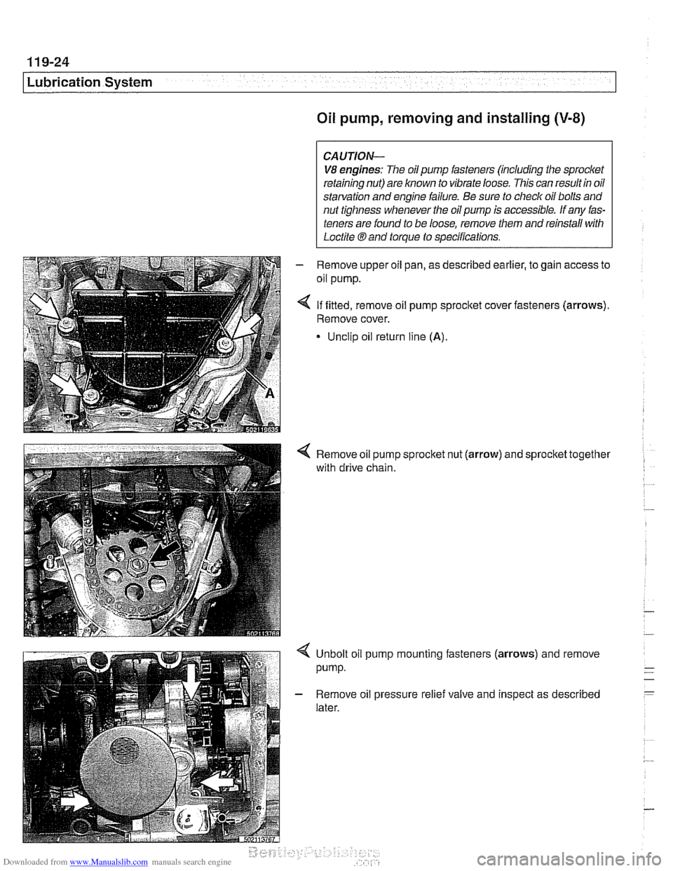
4 If fitted, remove oil pump sprocket cover fasteners (arrows).
Remove cover.
* Unclip oil return line (A).
4 Remove oil pump sprocket nut (arrow) and sprocket together
with drive chain.
Unbolt oil pump mounting fasteners (arrows) and remove
pump.
Remove oil pressure relief valve and inspect as described
later.
Page 358 of 1002
Downloaded from www.Manualslib.com manuals search engine
.-
ignition System
Disabling ignition system
The ignition system operates in a lethal voltage range and
should be disabled any time engine service or repair work is
being done that requires the ignition to be switched on.
The engine management system can be disabled by remov-
ing the DME main relay. The relay is located in the electronics
box (E-box) in the left rear of the engine
compartment, be.
neath the interior microfilter housing.
CAUTION- Relay locations may
vary. Use care when identifying relays.
See
610 Electrical Component Locations.
Checking for spark
CAUTION-
If
a spark test is done incorrecth damage to the Engine Con-
trol Module
(ECM) or the ignition coils may result.
NOTE-
Spark plug replacement is covered in 020 Maintenance.
Check~ng for spark is d~fflcult on englnes wlth d~str~butorless
ignition systems.
Try removing the spark plugs and inspecting for differences between them.
A poor-firing plug may be wet with fuel and/or ~. - ~
black and sooty, but not always. If a coil is not operating, the
engine management system will electrically disable the fuel
injector to that cylinder. The key is to look for differences be-
tween cylinders.
Ignition coil assembly, testing and
replacing
C4 UTION-
Use a digital multimeter for the following tests. I
- Remove plastic engine cover from top of valve cover by pry-
ing off bolt covers and removing cover mounting bolts.
- Raise car slowly while constantly checking position of jack
and car.
- Disconnect harness connector from coil. Connect multimeter
between terminal 15
(+) in connector and ground.
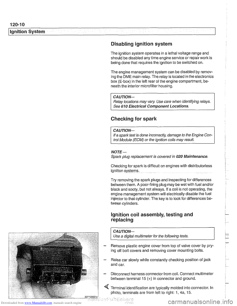
4 Terminal identification are typically molded into connector. In
photo, terminals are from left to right: 1,
4a, 15.
Page 361 of 1002
Downloaded from www.Manualslib.com manuals search engine
ignition System
Crankshaft speed sensor, replacing (M62 and M62TU
engines)
The crankshaft speed sensor reads a toothed pulse wheel
mounted on the flywheel.
If the Engine Control Module(ECM)
does not receive an impulse signal from the crankshaft speed
sensor during
cranking, the engine will not start. If the OBD II
system misfire detection protocol detects a catalyst damag-
ing fault due to a malfunction in the crankshaft speed sensor
components, the Check Engine light (Malfunction
Indicator
Light or MIL) will be Illuminated.
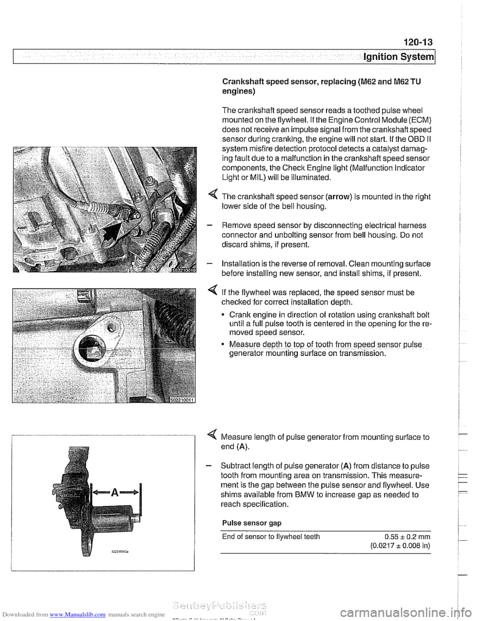
4 The crankshaft speed sensor (arrow) is mounted in the right
lower side of the bell housing.
- Remove speed sensor by disconnecting electrical harness
connector and unbolting sensor from bell housing. Do not
discard shims, if present.
- Installation is the reverse of removal. Clean mounting surface
before installing new sensor, and install shims, if present.
< If the flywheel was replaced, the speed sensor must be
checked for correct installation depth.
* Crank engine in direction of rotation using crankshaft bolt
until a full pulse tooth is centered in the opening for the re-
moved speed sensor.
Measure depth ro top of tooth from speed sensor p~lse
generator mounting s~rface on transmission.
4 Measure length of pulse generator from mounting surface to
end (A).
- Subtract length of pulse generator (A) from distance to pulse
tooth from mounting area on transmission. This measure-
ment is the gap between the pulse sensor and flywheel. Use
shims available from BMW to increase gap as needed to
reach specification.
Pulse sensor
gap
End of sensor to flywheel teeth 0.55 + 0.2 rnrn
(0.0217 t 0.008 in)
Page 362 of 1002
Downloaded from www.Manualslib.com manuals search engine
I Ignition System
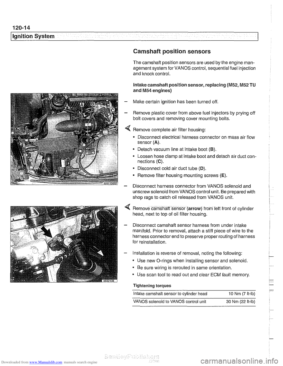
Camshaft position sensors
The camshaft position sensors are used by the englne man-
agement system for VANOS control, sequential fuel injection
and knock control.
Intake camshaft position sensor, replacing
(M52,M52 TU
and M54 engines)
- Make certain ignition has been turned off.
- Remove plastic cover from above fuel injectors by prying off
bolt covers and removing cover mounting bolts.
Remove complete air filter housing:
Disconnect electrical harness connector on mass air flow
sensor
(A).
Detach vacuum line at intake boot (B).
Loosen hose clamp at intake boot and detach air duct con-
nections
(C).
* Disconnect cold air duct tube (D).
Remove filter housing mounting screws (E).
- Disconnect harness connector from VANOS solenoid and
unscrew solenoid from VANOS control unit. Be prepared with
shop rags to catch oil released from VANOS unit.
Remove camshaft sensor (arrow) from
left front of cyl~nder
head, next to top of oil filter housing.
Disconnect camshaft sensor harness from under intake
manifold. Prior to removal, attach a stiff piece of wire to the
harness connector end to preserve proper routing of harness
for reinstallation.
Installation is reverse of removal, noting the following:
Use new O-rings when installing sensor and solenoid.
Be sure wiring is rerouted in same orientation.
Use scan tool to read out and clear
ECM fault memory
Tightening torques
-
Intake camshaft sensor to cylinder head 10 Nrn (7 ft-lb)
VANOS solenoid to VANOS control unit 30 Nm (22 ft-lb)
Page 364 of 1002
Downloaded from www.Manualslib.com manuals search engine
120-1 6
Ignition System
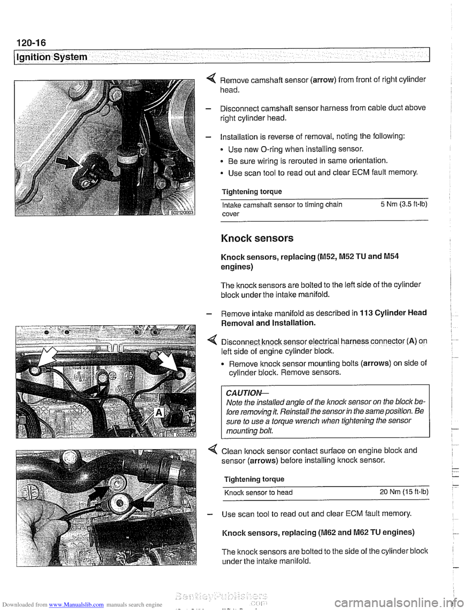
Remove camshaft sensor (arrow) from front of right cylinder
head.
Disconnect camshaft sensor harness from cable duct above
right cylinder head.
Installation is reverse of removal, noting the following:
Use new O-ring when installing sensor.
Be sure wiring is rerouted in same orientation.
Use scan tool to read out and clear ECM fault memory.
Tightening torque Intake camshaft sensor to timing chain 5 Nm
(3.5 ft-lb)
cover
Knock sensors
Knock sensors, replacing (M52, M52 TU and M54
engines)
The knock sensors are bolted to the left side of the cylinder
block under the intake manifold.
- Remove intalte manifold as described in 113 Cylinder Head
Removal and Installation.
D~sconnect knock sensor electrical harness connector (A) on
left side of engine cylinder block.
Remove knock sensor
mount~ng bolts (arrows) on side of
cyllnder block. Remove sensors.
Note the installed angle of the
lnocl~ sensor on the bloc/( be-
fore removing it. Reinstall the sensor
in the same position. Be
sure to use a torque wrench when tightening the sensor
mounting bolt.
< Clean lknock sensor contact surface on engine bloclc and
sensor (arrows) before installing
ltnock sensor.
Tightening torque
Knock sensor to head 20 Nm (15 ft-lb)
- Use scan tool to read out and clear ECM fault memory.
Knock sensors, replacing
(M62 and M62 TU engines)
The
knock sensors are bolted to the side of the cylinder block
under the
intake manifold.
Page 365 of 1002
Downloaded from www.Manualslib.com manuals search engine
Ignition System
Remove intake manifold as described in 113 Cylinder Head
Remaval and Installation.
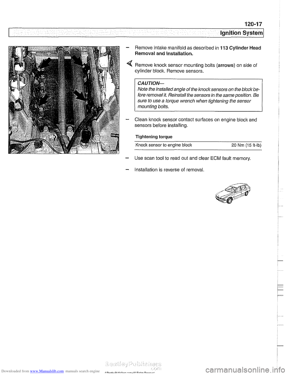
Remove knock sensor mounting bolts (arrows) on side of
cylinder block. Remove sensors.
I CAUTION- I
Note the installedangle of the knock sensors on the bloclt be-
fore removalit. Reinstall the sensors in the same position. Be
sure to use
a torque wrench when tightening the sensor
mounting bolts.
Clean
lknoclc sensor contact surfaces on engine bloclc and
sensors before installing.
Tightening torque
Knock sensor to engine
bloclc 20 Nm (15 ft-lb)
- Use scan tool to read out and clear ECM fault memory.
- Installation is reverse of removal.
Page 375 of 1002
Downloaded from www.Manualslib.com manuals search engine
121-9
Battery, Starter, ~lternatorl
Battery charging
Discharged batteries can be recharged using a batterycharg-
er. Remove the battery from the trunk during charging.
Prolonged charging causes electrolyte evaporation to a level
that can damage the battery. It is best to use a low-current
charger
(6 amperes or less) to prevent battery damage
caused by overheating.
WARNING -
Hydrogen gas given off by the battery during charging is ex-
plosive. Do not smoke.
Keep open flames away from the top
ofthe batte~ and prevent electrical sparks by turning off the
battery charger before connecting or disconnecting it.
Battery electrolyte (sulfuric acid) can damage the car. If
electrolyte is spilled, clean the area with a solution
ofbak-
ing soda and water.
Always allow a frozen battery to thaw before attempting
to recharge it.
Always disconnect both battery cables and remove bat-
tery from vehicle during battery charging. Do not ex-
ceed
16.5 charging voltage at the battery
Battery safety terminal, replacing
If the battery safety terminal has been triggered, investigate
and correct the cause prior to replacement.
- Working in right side of luggage compartment, remove bat-
tery trim panel.
- Disconnect negative (-) battery terminal and cover with
insulator.
- Disconnect positive (+) cable from battery.
- Release positive (+) cable from cable brackets on luggage
compartment wall. Lay new repair cable parallel to positive
cable.
- Mark off length of new cable on old cable. Allow 10 cm
(2.5 in) of slack.
- Saw through old cable.
Do not use bolt cutters or similar tools to cut through cable.
A cable end that has been squashed
flat will not fit into the
Page 381 of 1002
Downloaded from www.Manualslib.com manuals search engine
Battery, Starter, ~lternatorl
Alternator, removing and installing
(6-cylinder engine)
A replacement alternator should have the same rating as the
original. Alternator manufacturer and ampere rating are nor-
mally marked on the alternator housing.
- Disconnect negative (-) battery cable.
CAUTION-
Prior to disconnecting the batteg read the battery discon-
nection cautions given
in 001 General Warnings and Cau-
I tions.
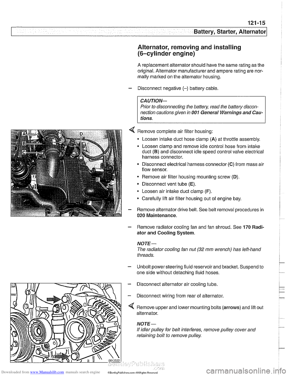
Remove complete air filter housing:
Loosen intake duct hose clamp
(A) at throttle assembly.
Loosen clamp and remove idle control hose from intake
duct
(B) and disconnect idle speed control valve electrical
harness connector.
Disconnect electrical harness connector
(C) from mass air
flow sensor.
* Remove air filter housing mounting screw (D),
Disconnect vent tube (E).
Loosen air intake duct clamp (F).
Carefully lifl air filter housing out of engine bay.
Remove alternator drive belt. See belt removal procedures in
020 Maintenance.
- Remove radiator cooling fan and fan shroud. See 170 Radi-
ator and Cooling System.
NOTE-
The radiator cooling fan nut (32 mm wrench) has left-hand
threads.
- Unbolt power steering fluid reservoir and bracket. Suspend to
one side without detaching fluid hoses.
- Disconnect alternator air cooling tube.
- Disconnect wiring from rear of alternator.
'4 Remove upper and lower mounting bolts (arrows) and lift
alternator.
If idler pulley for belt interferes, remove pulley cover and
retaining bolt to remove pulley. out
Page 384 of 1002
Downloaded from www.Manualslib.com manuals search engine
121-18
I Battery, Starter, Alternator
Alternator, removing and installing
(M62 TU engine, water cooled)
V-8 models produced after 9/98 are equipped with a water
cooled alternator.
CAUTION-
Allow engine to cool before removing alternator as coolant
will
escape from the alternator water jacket.
- Disconnect negative (-) battery cable
CAUTION- Prior to disconnecting the
battew read the battery discon-
nection cautions given in
001 General Warnings and Cau-
tions.
- Remove radiator cooling fan and fan shroud. See 170 Radi-
ator and Cooling System.
- Drain engine cooling system. See 170 Radiator and Cool-
ing System.
- Remove alternator drive belt. See 020 Maintenance.
- Disconnect battery lead (terminal 30 or B+) and two-pin har-
ness connector from front of alternator.
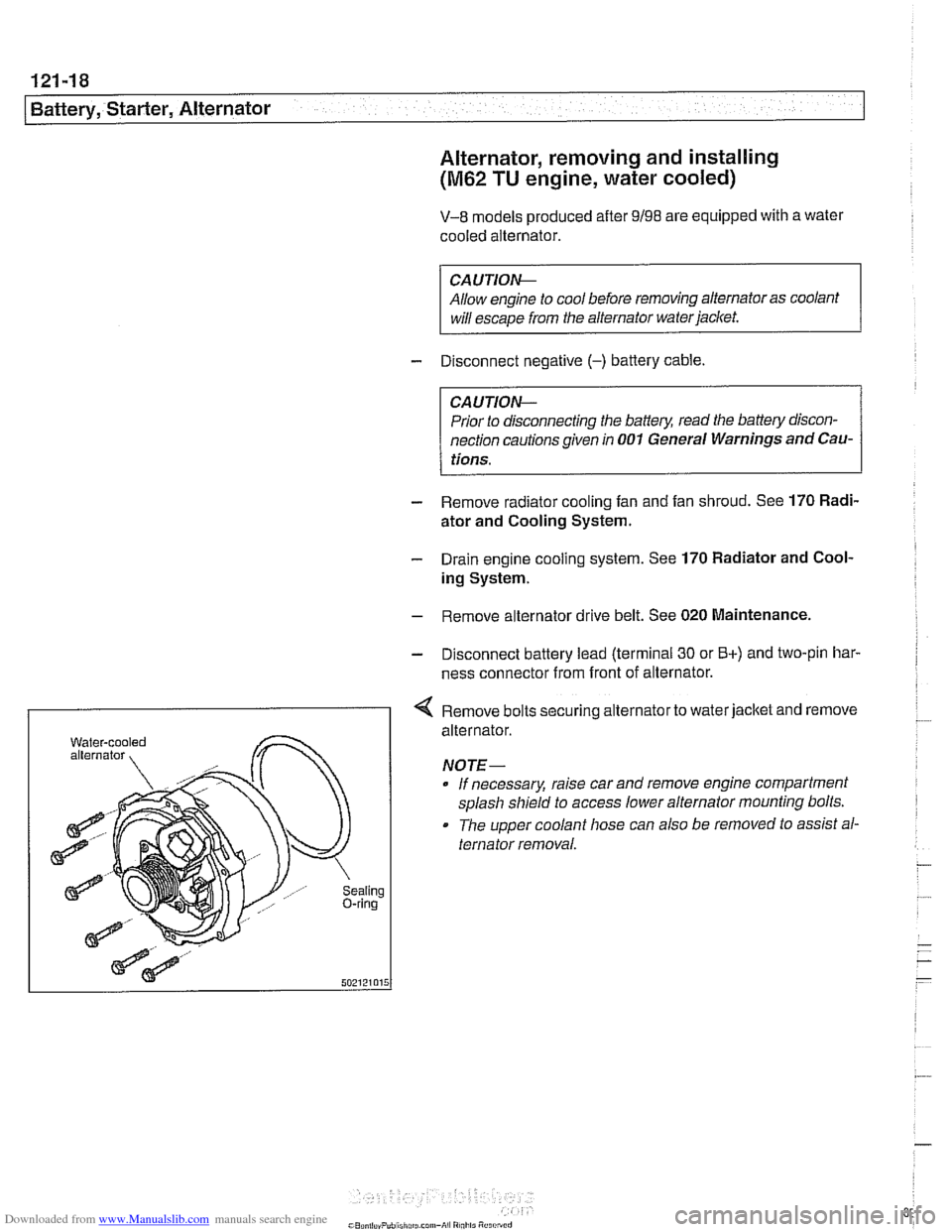
I < Remove bolts securing alternator to water jacket and remove
aling ring
alternator.
NOTE- If necessary, raise car and remove engine compartment
splash shield to access lower alternator mounting bolts.
The upper coolant hose can also
be removed to assist al-
ternator removal.