replacing BMW 540i 1997 E39 Workshop Manual
[x] Cancel search | Manufacturer: BMW, Model Year: 1997, Model line: 540i, Model: BMW 540i 1997 E39Pages: 1002
Page 888 of 1002
Downloaded from www.Manualslib.com manuals search engine
interior Trim
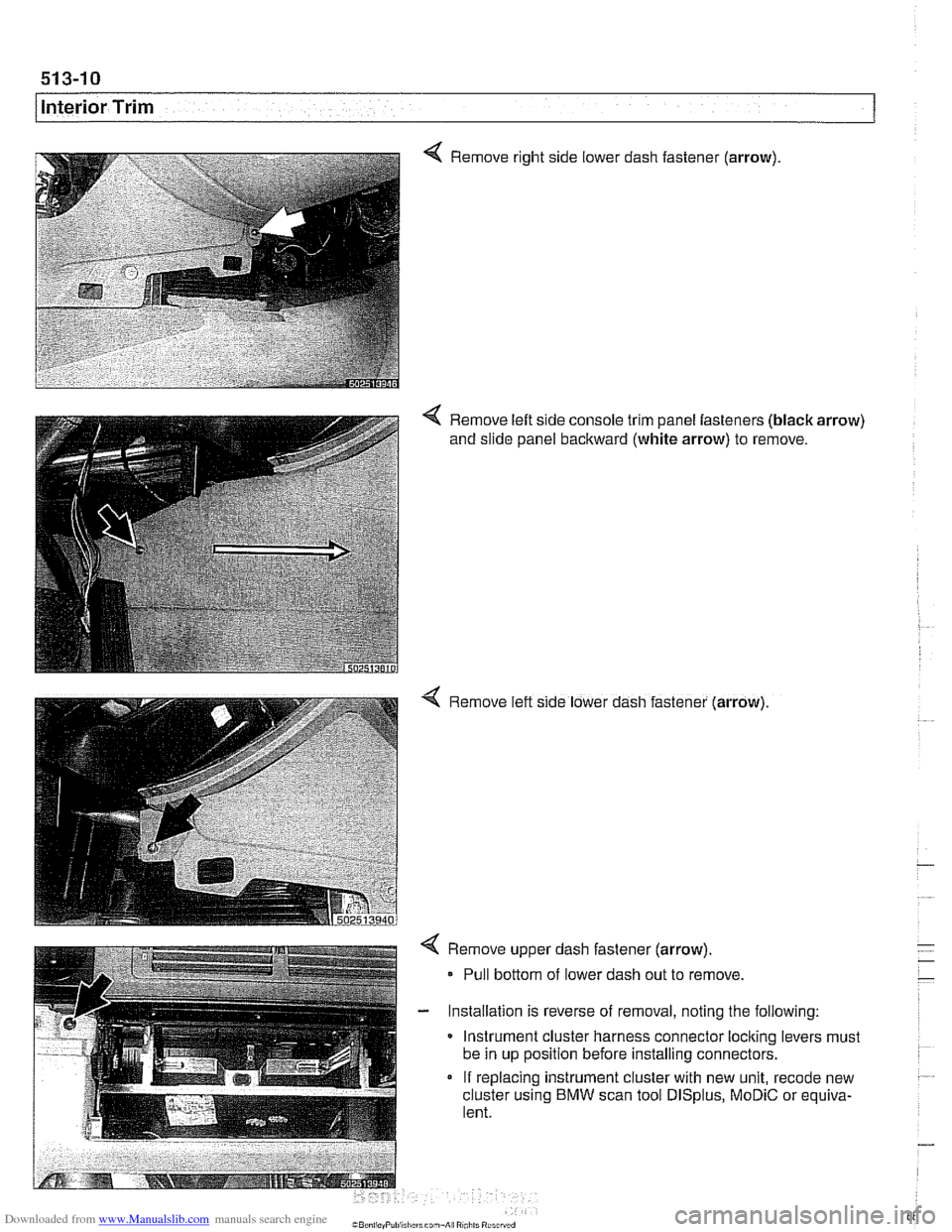
Remove right side lower dash fastener (arrow)
< Remove left side console trim panel fasteners (black arrow)
and slide panel backward (white arrow) to remove.
4 Remove left slde lower dash fastener (arrow)
4 Remove upper dash fastener (arrow).
- Pull bottom of lower dash out to remove
- Installation is reverse of removal, noting the following:
Instrument cluster harness connector
loclting levers must
be in up position before installing connectors.
If replacing instrument cluster with new unit,
recode new
cluster using
BMW scan tool DISplus, MoDiC or equiva-
lent.
Page 895 of 1002
Downloaded from www.Manualslib.com manuals search engine
51 5 Central Locking and Anti-Theft
........................... General .51 5.2
Central Locking ................... .51 5.2
General Module
..................... .51 5.2
Central locking inputs and outputs
....... .51 5.3
Doorlocks
........................... 515-5
Trunklock
........................... 515-7
Remote entry (FZV)
.................. .51 5.7
Remote entry (FZV) inputs and outputs ... .51 5.8
Car Memory I Key Memory ............ .51 5.12
Trunk lid soft close (SCA)
............. .51 5.13
SCA subsystem
.................... .51 5.14
........ Tailgate and rear window locks
.51 5.14
Sport Wagon tailgate and rear
window
lock schematic ............... .51 5.15
Door Handles and Locks .......... .51 5.16
Door handle (outer), removing
and installing
....................... .51 5.16
Door latch, removing and installing
..... .51 5.17
Outer door lock cylinder, removing
and installing
....................... .51 5.18
Trunk Lock Assembly ............. 515-1 9
Trunk lock. removing and installing
...... 515-19
Trunk lock striker plate. removing
and installing
....................... 515-20
Tailgate lock. emergency release
....... 515-21
... Electronic Immobilization (EWS) 515-21
EWS variations
..................... 515-22
......... EWS control module. replacing 515-23
Transmitter
1 receiver module .......... 515-23
....................... Ring antenna 515-23
Anti-theft System (DWA) ........... 51 5-24
DWA LED Status
.................... 51 5-24
Tilt sensor
......................... 515-24
Interior protection .................... 51 5-25
Glass breakage sensors
.............. 515-26
Emergency disarming
................ 51 5-26
Page 904 of 1002
Downloaded from www.Manualslib.com manuals search engine
1 Central Locking and Anti-Theft
NOJE-
A single unlock request from the driver's door with the FZV
key unlocks the driver's door only.
A second unlock request
unlocls the remaining doors and trunk. This feature can be
modified for individual users with the Key Memory capabil-
ities to activate all lock actuators simultaneously See Car
Memory
/ Key Memory later in this section.
Starting with 2000 models, the battery in the FZV ignition
Icey is recharged by the ignition switch ring antenna while
the ley is in the ignition switch.
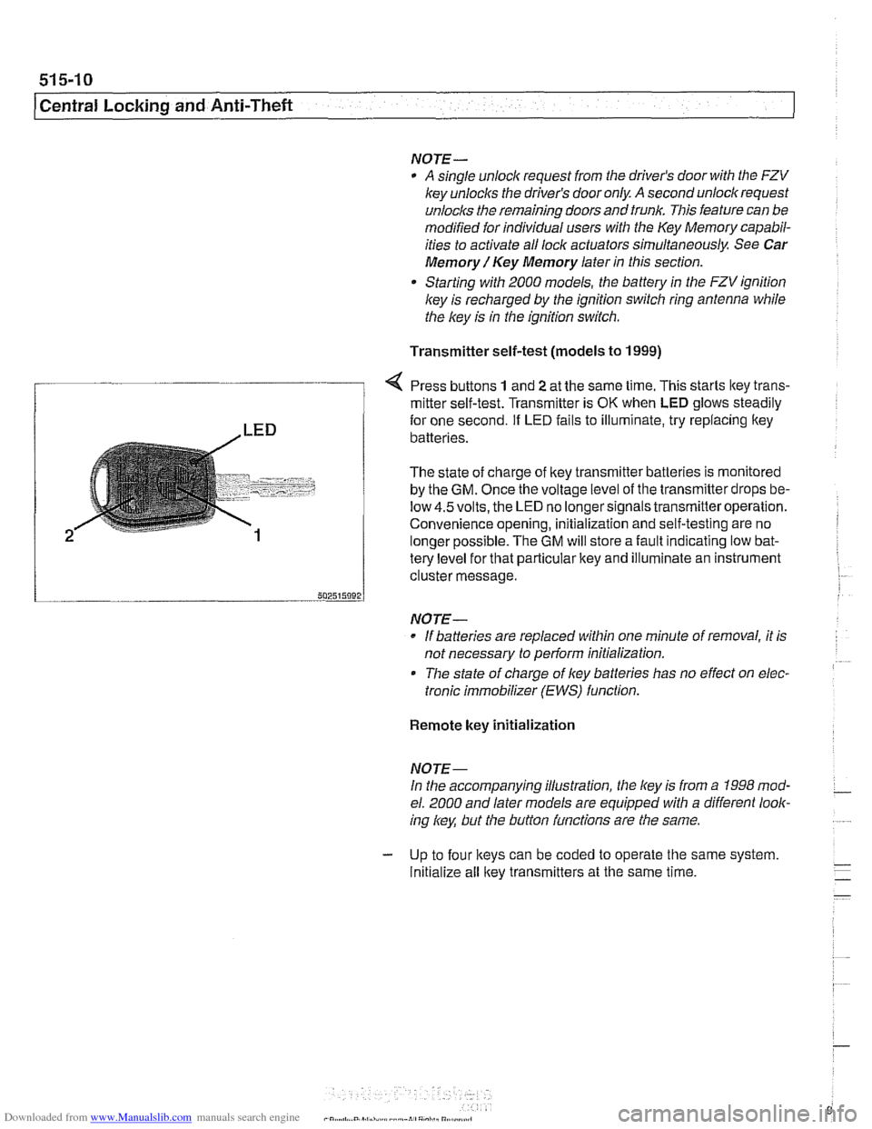
Transmitter self-test (models to
1999)
Press buttons 1 and 2 at the same time. This starts ltey trans-
/ mitter self-test. Transmitter is OK when LED glows steadily
te{le"el for that particular key and illuminate an instrument
cluster message.
-- 502515092 J
NO JE-
If batteries are replaced within one minute of removal, it is
not necessary to
periorm initialization.
Tlie state of charge of key batteries has no effect on elec-
tronic immobilizer (EWS) function.
2
Remote key initialization
for one second. If LED fails to illuminate, try replacing ltey~
batteries.
The state of charge of key transmitter batteries is monitored
by the
GM. Once the voltage level of the transmitter drops be-
low
4.5volts, the LED no longersignals transmitteroperation.
Convenience opening, initialization and self-testing are no
lonaer ~ossible. The GM will store a fault indicatina low bat-
NOJE-
In the accompanying illustration, the key is from a 1998 mod-
el. 2000 and later models are equipped with a different look-
ing
/
Initialize all key transmitters at the same time.
Page 917 of 1002
Downloaded from www.Manualslib.com manuals search engine
Central Lockina and ~nti- heft
EWS control module, replacing
NOTE-
EWS control module location varies depending on version of
EWS installed.
Checlc the table €39 EWS applications.
- Disconnect battery negative (-) cable.
CA UTIOI\C
Prior to disconnecting the battery, read the battery discon-
nection cautions given in
001 General Warnings and Cau-
tions.
- EWS II: Control module is accessible from behind glove com-
partment.
Remove trim below glove compartment.
Lower relay and module holder to access EWS control
module
EWS
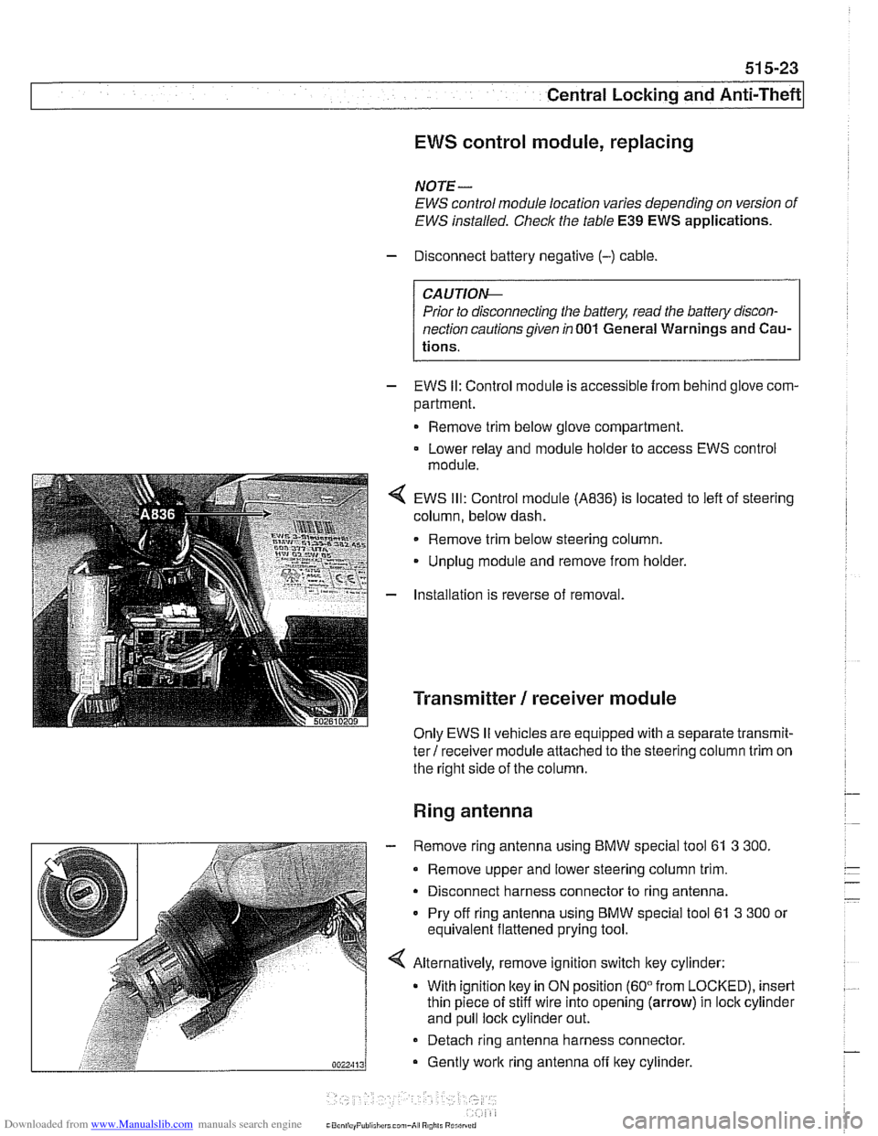
Ill: Control module (A836) is located to left of steering
column, below dash.
Remove trim below steering column.
Unplug module and remove from holder.
Installation is reverse of removal.
Transmitter / receiver module
Only EWS II vehicles are equipped with a separate transmit-
ter! receiver module attached to the steering column trim on
the right side of the column.
Ring antenna
- Remove ring antenna using BMW special tool 61 3 300.
Remove upper and lower steering column trim.
Disconnect harness connector to ring antenna.
Pry off ring antenna using
BMW special tool 61 3 300 or
equivalent flattened prying tool.
Alternatively, remove ignition switch key cylinder: With ignition
ltey in ON position (60" from LOCKED), insert
thin piece of stiff wire into opening (arrow) in lock cylinder
and pull lock cylinder out.
- Detach ring antenna harness connector.
Gently
work ring antenna off ltey cylinder.
CaonliayPuliiliirrl can,-A, R0,il. Rurilrrrri
Page 929 of 1002
Downloaded from www.Manualslib.com manuals search engine
540 Sunroof
General . . . . . . . . . . . . . . . . . . . . . . . . . . . ,540-2
Sunroof Adjustments. . . . . . . . . . . . . . . .540-2
Sunroof electronic controls, initializing . . . . ,540-2
Sunroof, normalization. . . . . . . . . . . . . . . . . ,540-3
Sunroof, characteristic curve . . . . . . . . . . . .540-3
Sunroof panel, emergency closing . . . . . . . ,540-4
Sunroof, adiustino . . . . . . . . . . . . . . . . . . . . ,540-5
~unroofwitil steel roof panel, adjusting . . . ,540-5
Sunroof with glass roof panel, adjusting . . . ,540-7
Sunroof Components . . . . . . . . . . . . . . 540-8
Sunroof components (glass)
. . . . . . . . . . . . 540-8
Sunroof panel, removing and
installing (steel or glass)
. . . . . . . . . . . . . . . 540-8
Sunroof panel gasket, replacing
(steel or glass)
. . . . . . . . . . . . . . . . . . . . . . . 540-9
Sunroof motor, replacing
. . . . . . . . . . . . . . 540-10
Page 937 of 1002
Downloaded from www.Manualslib.com manuals search engine
Sunroof
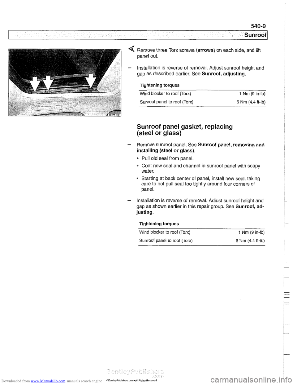
4 Remove three Torx screws (arrows) on each side, and lift
panel out.
- Installation is reverse of removal. Adjust sunroof height and
gap as described earlier. See Sunroof, adjusting.
Tightening torques
Wind blocker to roof (Torx)
1 Nm (9 in-lb)
Sunroof panel to roof (Torx)
6 Nm (4.4 ft-lb)
Sunroof panel gasket, replacing
(steel
or glass)
- Remove sunroof panei. See Sunroof panei, removing and
installing (steel or glass).
Pull old seal from panel.
Coat new seal and channel in sunroof panel with soapy
water.
* Starting at back center of panel, install new seal, taking
care to not pull seal too tightly around four corners of
panel.
- Installation is reverse of removal. Adjust sunroof height and
gap as shown earlier in this repair group. See Sunroof, ad-
justing.
Tightening torques
Wind
bloclter to roof (Torx)
Sunroof panel to roof (Torx) 1 Nm (9 in-lb)
6 Nrn (4.4 ft-lb)
Page 938 of 1002
Downloaded from www.Manualslib.com manuals search engine
.-
Sunroof
Sunroof motor, replacing
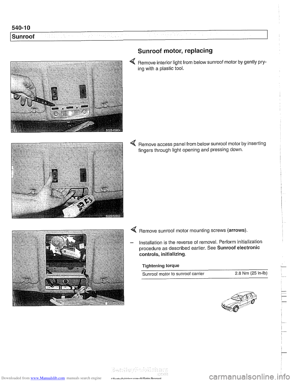
Remove interior light from below sunroof motor by gently pry-
ing with a plastic tool.
4 Remove access panel from below sunroof motor by inserting
fingers through light opening and pressing down.
4 Remove sunroof motor mounting screws (arrows).
- Installation is the reverse of removal. Perform initialization
procedure as described earlier. See Sunroof electronic
controls, initializing.
Tightening
torque
Sunroof motor to sunroof carrier 2.8 Nm (25 in-lb)
Page 941 of 1002
Downloaded from www.Manualslib.com manuals search engine
Seat Belts
NOTE-
The rear bench seat belt strap may not retract fully due to in-
creased friction between strap and seat cover.
A small re-
maining loop in belt strap when fully retracted is acceptable.
WARNING-
* For maximum protection from injury, seat bells should be
replaced as a set (including all hardware), if they are sub-
ject to occupant loading in a collision.
Seat belts should not be modified or repaired. The seat
belt mounting points should not be changed or modi-
fied.
Do not bleach or dye seat belt webbing. Webbing that
is severely faded or
redyed will not meet the strength
requirements of a collision and must be replaced.
Clean belts with a luke-warm soap solution only:
Seat belts should be periodically inspected for webbing
defects such as cuts or pulled threads.
* Immediately after replacing a damaged or worn seat
belt, destroy the old belt to prevent it from being used
again.
Page 949 of 1002
Downloaded from www.Manualslib.com manuals search engine
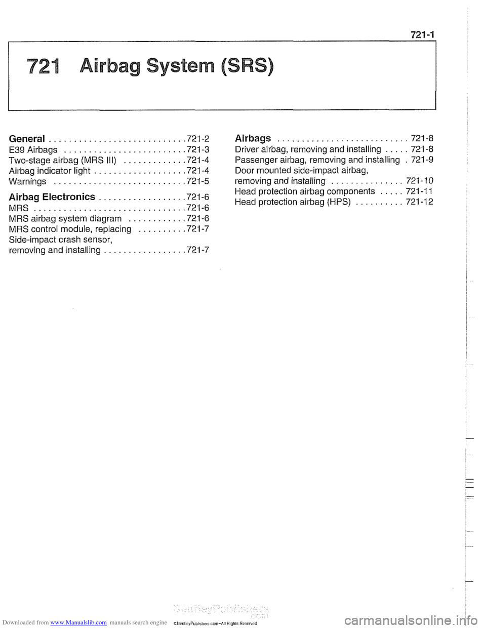
721 Airbag System (SRS)
........................... General ............................ 721-2 Airbags 721-8
..... E39Airbags ......................... 721-3 Driver airbag. removing and installing 721-8
Two-stage airbag (MRS 111) ............ .72 1.4 Passenger airbag. removing and installing . 721-9
Airbag indicator light .................. .72 1.4 Door mounted side-impact airbag.
............... Warninas .......................... .72 1.5 removina and installina 721-10 .
..... Head protection airbag components 721
-1 1 Airbag Electronics ................. '721-6 Head protection airbag (HpS) .......... 721-12 MRS ............................... 721-6
MRS
airbag system diagram ........... .72 1.6
MRS control module. replacing ......... .72 1.7
Side-impact crash sensor.
removing and installing
................ .72 1.7
Page 955 of 1002
Downloaded from www.Manualslib.com manuals search engine
Airbag System (SRS)~
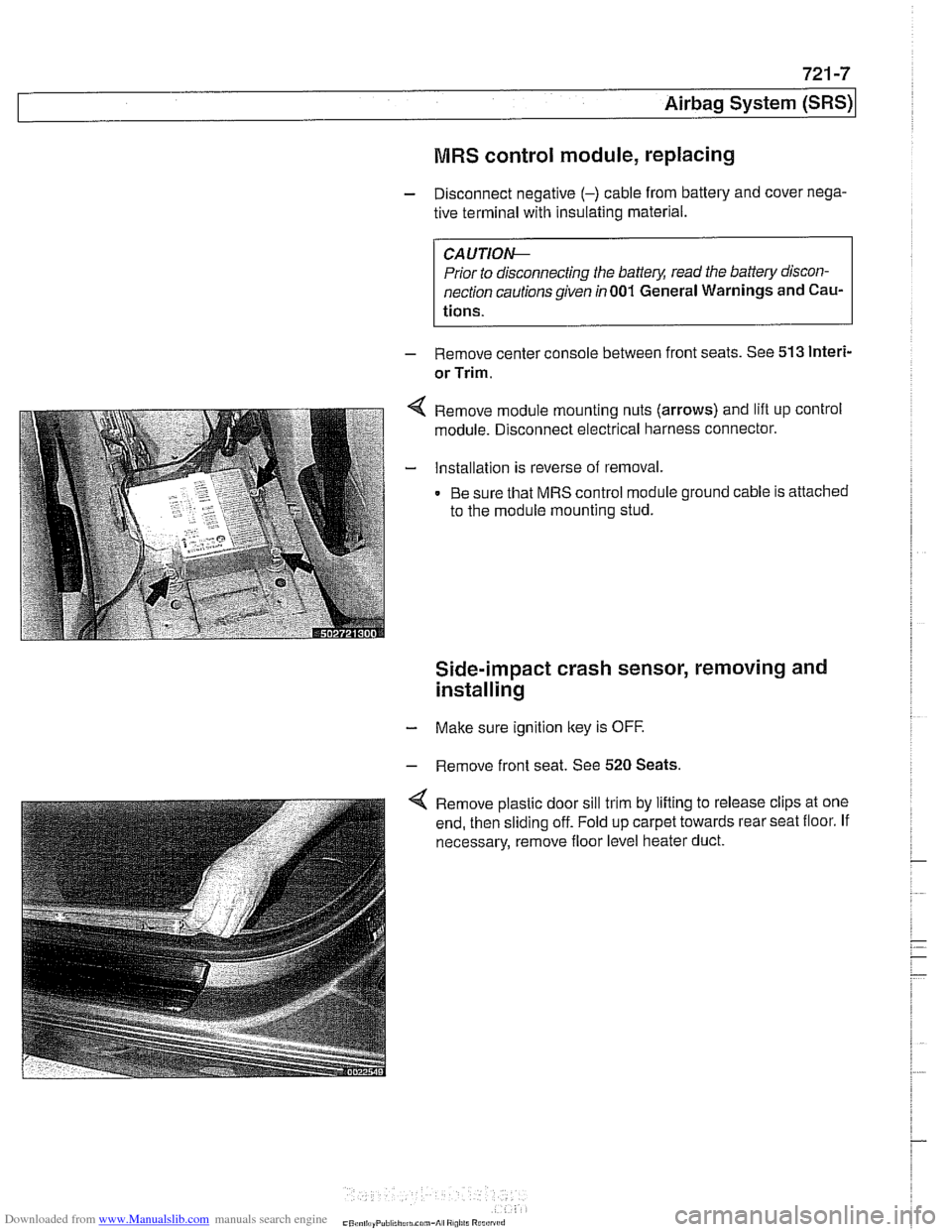
MRS control module, replacing
- Disconnect negative (-) cable from battery and cover nega-
tive terminal with insulating material.
CAUTIOI\C
Prior to disconnecting the battery, read the battery discon-
nection cautionsgiven in001 General Warnings and
Cau-
tions.
- Remove center console between front seats. See 513 lnteri-
or Trim.
Remove module mounting nuts (arrows) and lift up control
module. Disconnect electrical harness connector.
Installation is reverse of removal.
Be sure that MRS control module ground cable is attached
to the module mounting stud.
Side-impact crash sensor, removing and
installing
- Make sure ignition key is OFF.
- Remove front seat. See 520 Seats.
Remove plastic door sill trim by lifting to release clips at one
end, then sliding off. Fold up carpet towards rear seat floor. If
necessary, remove floor level heater duct.