replacing BMW 540i 1997 E39 Workshop Manual
[x] Cancel search | Manufacturer: BMW, Model Year: 1997, Model line: 540i, Model: BMW 540i 1997 E39Pages: 1002
Page 754 of 1002
Downloaded from www.Manualslib.com manuals search engine
. .
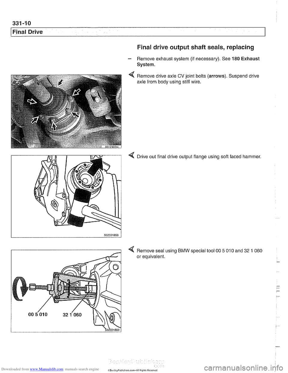
Final Drive Final drive output shaft seals, replacing
- Remove exhaust system (if necessary). See 180 Exhaust
System.
Remove drive axle
CV joint bolts
axle from body using stiff wire. (arrows).
Suspend drive
4 Drive out final drive output flange using soft faced hammer.
4 Remove seal using BMW special tool 00 5 010 and 32 1 060
or equivalent.
Page 756 of 1002
Downloaded from www.Manualslib.com manuals search engine
331-12
Final Drive Final drive cover, removing and installing
- Remove final drive. See Final drive, removing and install-
ing.
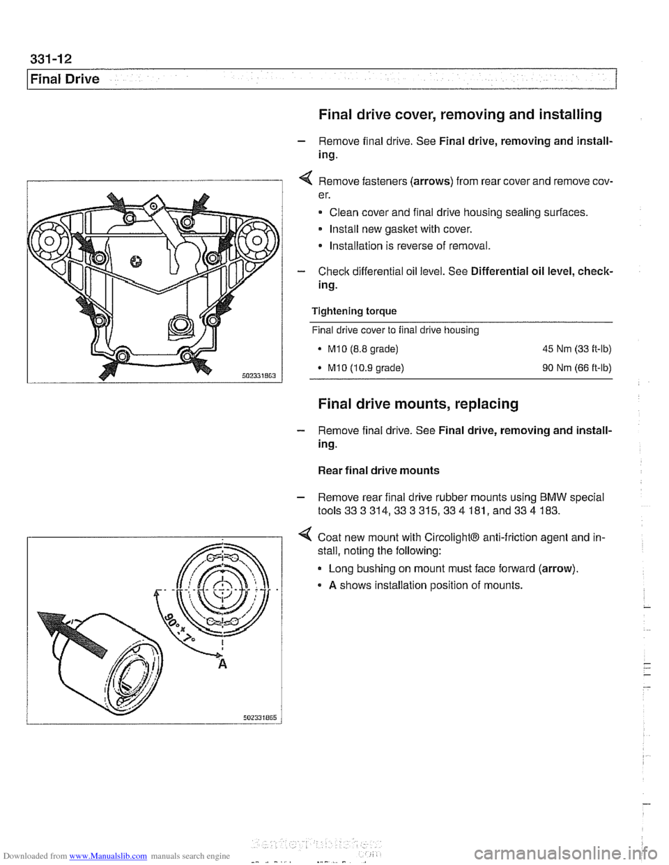
I 1 4 Remove fasteners (arrows) from rear cover and remove cov-
er.
Clean cover and final drive housing sealing surfaces.
Install new
gasket with cover.
* Installation is reverse of removal.
- Check differential oil level. See Differential oil level, check-
ing.
Tightening
torque
Final drive cover to final drive housing
. M10 (8.8 grade) 45 Nm (33 ft-lb)
M10 (10.9 grade) 90 Nm (66 ft-lb)
Final drive mounts, replacing
- Remove final drive. See Final drive, removing and install-
ing.
Rear final drive mounts
- Remove rear final drive rubber mounts using BMW special
tools333314,333315,334 181, and334 183.
4 Coat new mount with CircolightB anti-friction agent and in-
.
stall, noting the following:
Long bushing on mount must face forward (arrow).
A shows installation position of mounts.
Page 761 of 1002
Downloaded from www.Manualslib.com manuals search engine
331-17
Final ~rivel
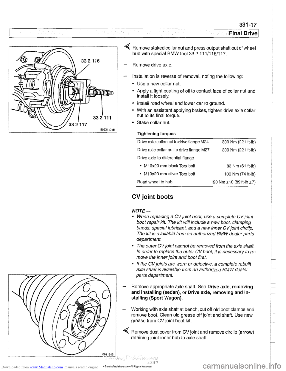
4 Remove staked collar nut and press output shaft out of wheel
hub with special
BMW tool 33 2 11 111 161117.
- Remove drive axle
- Installation is reverse of removal, noting the following:
* Use a new collar nut.
- Apply a light coating of oil to contact face of collar nut and
install it loosely.
Install road wheel and lower car to ground.
* With an assistant applying brakes, tighten drive axle collar
nut to its final torque.
Stake collar nut.
Tightening
torques
Drive axle collar nut to drive flange M24
300 Nrn (221 ft-lb)
Drive axle collar nut to drive flange M27
300 Nrn (221 ft-lb)
Drive axle to differential flange
M10x20 rnrn blaclc Torx bolt 83 Nrn (61 it-lb)
- M10x20 rnrn silver Torx bolt loo Nrn (74 ft-lb)
Road wheel to hub
120 Nrn+lO (89tt-lbi-7)
CV joint boots
NOTE-
When replacing a CVjoint boot, use a complete CVjoint
boot repair kit. The lit will include a new boot, clamping
bands, special lubricant, and a new inner CV joint circlip.
The lit is available from an authorized
BMW dealerparts
department.
The outer CVjoint cannot be removed from the axle
shaft
In order to replace the outer CV boot, it is necessary to re-
move the inner joint and boot first.
If the
CVjoints are worn or defective, a complete rebuilt
axle shaft is available from an authorized
BMW dealer
parts department.
- Remove appropriate axle shaft. See Drive axle, removing
and installing (sedan), or Drive axle, removing and in-
stalling (Sport Wagon).
- Working with axle shaft at bench, cut off old boot clamps and
remove boot. Clean old grease off joint and shaft. Use new
grease from CV joint boot kit.
4 Remove dust cover from CV joint and remove circlip (arrow)
retaining joint inner hub to axle shaft.
Page 763 of 1002

Downloaded from www.Manualslib.com manuals search engine
General ........................... .34 0.2
Special Tools
....................... .34 0.2
E39 brake system
.................... .34 0.4
Electronic braking and stability control
.... .34 0.4
Troubleshooting
..................... .34 0.5
Warnings and cautions
................ .34 0.7
Bleeding Brakes ................... .34 0.8
Brakes, bleeding
..................... .34 0.9
Brake Pads, Calipers and Rotors ... .34 0.1 1
Braking system components .......... .34 0.11
Brake pads,
checking and replacing ..... .34 0.12
Brake rotors, removing and installing
.... .34 0.15
Master Cylinder .................. .34 0.16
Master cylinder, removing and installing
. .34 0.17
Brake Booster .................... .349 0.1
Brake booster check valve
............ .34 0.19
Brake booster, removing and installing
.. .34 0.20
Parking Brake .................... .34 0.22
Parking brake components
............ .34 0.22
Parking
brake, adjusting .............. .34 0.22
Parking bralte shoes, removing
and installing
....................... .34 0.23
Parking
brake cable, replacing ......... .34 0.24
ABS Component Replacement ..... 340-26
Wheel speed sensor. replacing
......... 340-26
ABS impulse wheel
.................. 340-27
DSC lateral acceleration or
rotational rate (yaw) sensor. replacing
... 340-27
DSC steering angle sensor.
removing and installing
............... 340-28
DSC precharge pump.
removing and installing (1998 models)
... 340-29
DSC pressure sensor
(1 999 - 2002 models) ................ 340-30
ABS /traction electronic control
module
(1 997 -1 998 models) .......... 340-31
ABS
/ DSC control module
(1 999
- 2002 models) ................ 340-31
ABS
/ traction control hydraulic unit.
removing and installing
............... 340-31
Page 774 of 1002
Downloaded from www.Manualslib.com manuals search engine
340-1 2
Brakes Brake pads, checking and replacing
Brake pads can be replaced without disconnecting the brake
fluid hose from the caliper or having to bleed the brakes. The
rotors can be replaced without disassembling wheel hub and
bearing. Always machine or replace rotors in pairs. Replace
pads in sets.
Front and rear brake pad replacement procedures are identical.
WARNING -
* Altllough semi-metallic andmetallic brale friction materials
in brake pads or shoes no longer contain asbestos, they
produce dangerous dust.
Treat all
brale dust as a hazardous material.
Do not create dust by grinding, sanding, or cleaning
brake friction surfaces with compressed air.
CAUTION--
Pressing caliper piston in may cause brake fluid reservoir to
overflow To prevent this, use a clean syringe to first remove
some fluid
from reservoir.
Raise car and remove wheels,
WARNING-
Make sure that the car is firmly supported on jack stands de-
signed for the purpose. Place jack stands beneath structural
chassis points. Do not place jack stands under suspension
parts.
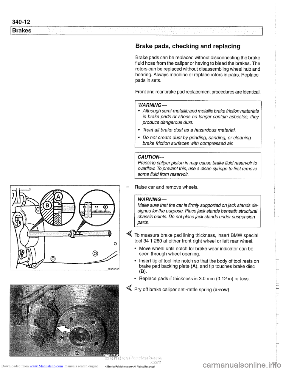
/ 4 To measure brake pad lining thickness, insert BMW special
n 1 tool 34 1 260 at either frontilght wheel or left rear wheel -
Move wheel until notch for brake wear indicator can be
seen through wheel opening.
Insert tip of tool into notch so that the body of tool rests on
brake pad backing plate
(A), and tip touches bralte disc
(B).
Replace pads if thickness is 3.0 mm (0.12 in) or less.
Pry off
bralte calipe~ , anti-rattle spring (arrow).
Page 783 of 1002
Downloaded from www.Manualslib.com manuals search engine
1 Brakes
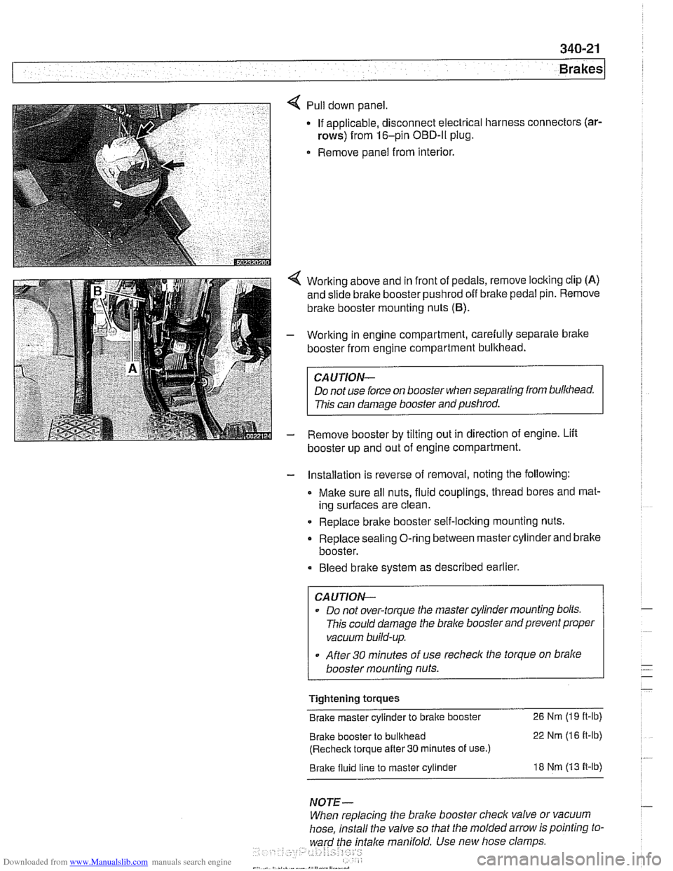
Pull down panel
If applicable, disconnect electrical harness
rows) from 16-pin OBD-ll plug.
Remove panel from interior. connectors
(ar-
Working
above and in front of pedals, remove locking clip (A)
and slide brake booster pushrod off bralte pedal pin. Remove
brake booster mounting nuts
(6).
Working in engine compartment, carefully separate bralte
booster from engine compartment bulkhead.
CAUTION-
Do not use force on booster when separating from bulkhead.
This can damage booster and pushrod.
Remove booster by tilting out in direction of engine. Lift
booster up and out of engine compartment.
- Installation is reverse of removal, noting the following:
Make sure all nuts, fluid couplings, thread bores and mat-
ing surfaces are clean.
Replace bralte booster self-locking mounting nuts.
Replace sealing O-ring between master cylinder and bralte
booster.
Bleed bralte system as described earlier.
CAUTION--
Do not over-torque tlie master cylinder mounting bolts.
This could damage the
bralce booster and prevent proper
vacuum build-up.
After
30 minutes of use recheclc the torque on bralce
booster mounting nuts.
Tightening torques
Brake master cylinder to brake booster
26 Nm (19 it-lb)
Brake booster to bulkhead 22 Nm (16 it-lb)
(Recheck torque after
30 minutes of use.)
Brake fluid line to master cylinder 18 Nm (13 it-lb)
NOTE-
When replacing the brake booster check valve or vacuum
hose, install the valve so that the molded arrow is pointing to-
ward the
fntalce manifold. Use new hose clamps
Page 784 of 1002
Downloaded from www.Manualslib.com manuals search engine
Brakes
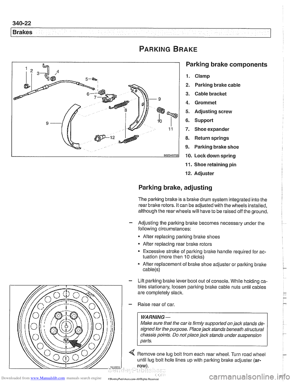
Parking brake components
1. Clamp
2. Parking brake cable
3. Cable bracket
4. Grommet
5. Adjusting screw
6. Support
7. Shoe expander
8. Return springs
9. Parking brake shoe
10. Lock down spring
11. Shoe retaining pin
12. Adjuster
Parking brake, adjusting
The parking brake is a brake drum system integrated into the I
rear brake rotors. It can be adjusted with the wheels installed,
although the rear wheels will have to be raised off the ground.
- Adjusting the parking bralte becomes necessary under the
following circumstances:
After replacing parking bralte shoes
After replacing rear brake rotors
Excessive stroke of parking brake handle required for ac-
tuation (more then
10 clicks)
After replacement of brake shoe adjuster or parking bralte
cable(s)
- Lift parking brake lever boot out of console. While holding ca-
Page 786 of 1002
Downloaded from www.Manualslib.com manuals search engine
340-24
Brakes
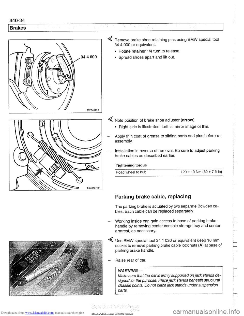
4 Remove brake shoe retaining pins using BMW special tool
34 4 000 or equivalent.
Rotate retainer
114 turn to release.
Spread shoes apart and lift out.
4 Note position of bralte shoe adjuster (arrow).
Right side is illustrated. Left is mirror image of this.
- Apply thin coat of grease to sliding parts and pins before re-
assembly.
- Installation is reverse of removal. Be sure to adjust parlting
bralte cables as described earlier.
Tightening torque
Road wheel to
hub 120 i lo Nm (89 i 7 ft-lb)
Parking brake cable, replacing
The parking brake is actuated by two separate Bowden ca-
bles. Each cable can be replaced separately.
- Working inside car, gain access to base of parking brake -
handle by removing center console storage tray and center
armrest, as necessary.
4 Use BMW special tool 34 1 030 or equivalent deep 10 mm
socket to remove parlting brake cable
loclc nuts (A) at base of
parking brake handle.
- Raise rear of car.
WARNING -
Male sure that the car is firmly supported on jack stands de-
signed for the purpose. Place jack stands beneath structural
chassis points. Do not place jaclc stands under suspension
Darfs.
Page 788 of 1002
Downloaded from www.Manualslib.com manuals search engine
1 Brakes
ABS COMPONENT REPLACEMENT
CA UTIOW-
If the tires on the car are of different makes, the ABS/trac-
tion controlsystem may overreact. Only fit tires of the same
make and treadpattern.
In adverse conditions, such as trying to rock the car out
of deep snow or other soft surface, or when snow
chains are fitted, it is advisable to switch off traction
control and allow
tlie car driveline to operate conven-
tionally.
All E39 vehicles are equipped with
Antilock Braking System
(ABS). Early production models featured ABS with Automatic
Stability Control (ABS
I ASC). Later models came equipped
with ABS and Dynamic Stability Control (ABS
/ DSC). This
manual will refer to these systems as ABS. ASC or DSC will
be specified when necessary.
For ABS system and component descriptions, see
300 Sus-
pension, Steering and Brakes-General.
Wheel speed sensor, replacing
- Raise applicable end of car.
Make sure that the car is firmly supported on
jack stands de-
signed for the purpose. Place
jack stands beneath structural
chassis points. Do not place jack stands under suspension
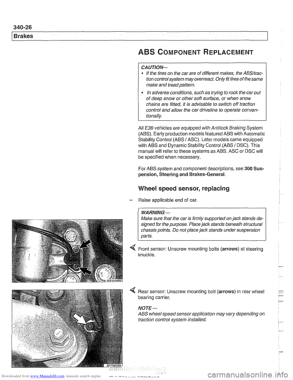
< Front sensor: Unscrew mounting bolts (arrows) at steering
knuckle.
4 Rear sensor: Unscrew mounting bolt (arrows) in rear wheel
bearing carrier.
NOTE-
ABS wheelspeed sensor application may vary depending on
traction control system installed.
Page 789 of 1002
Downloaded from www.Manualslib.com manuals search engine
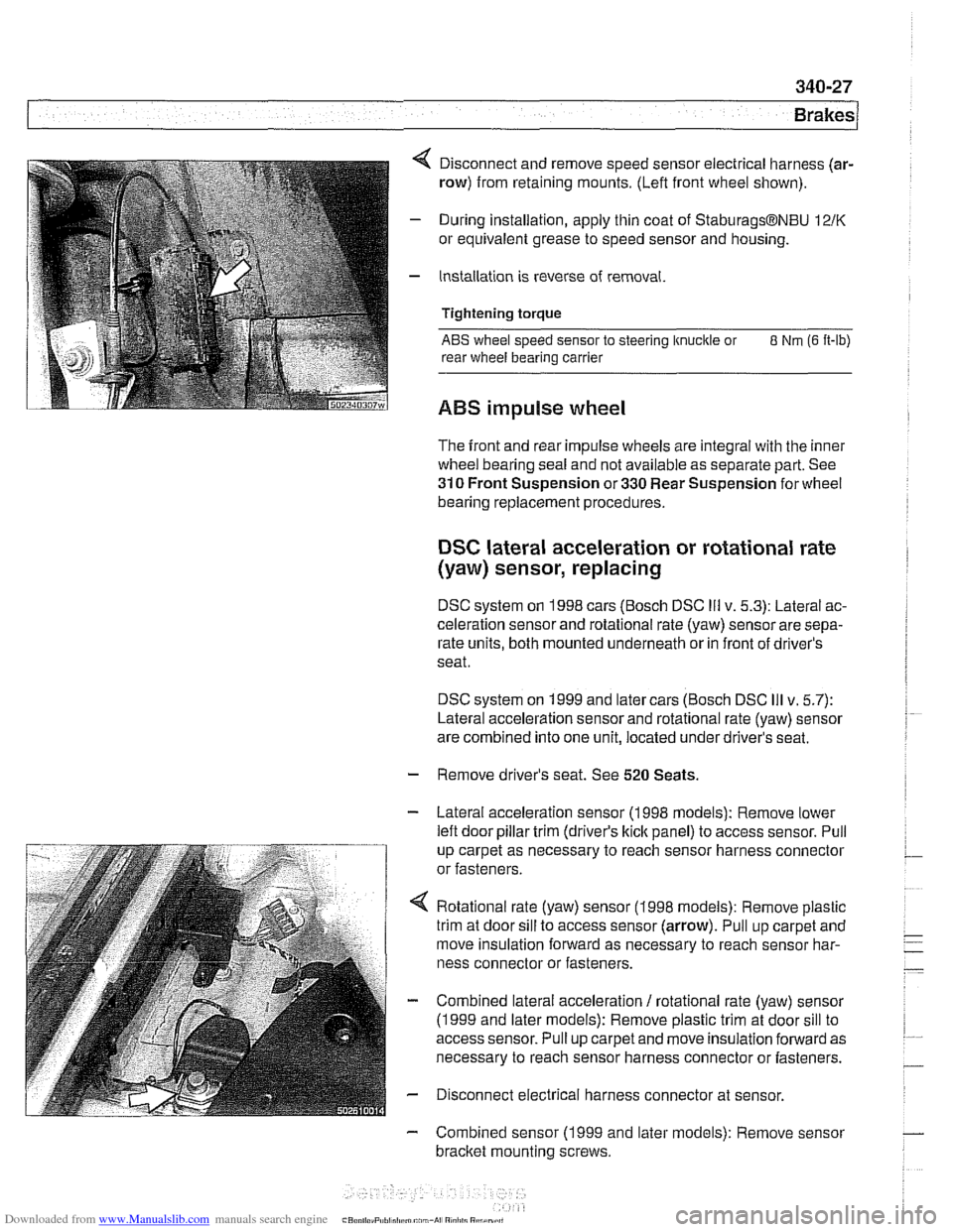
4 Disconnect and remove speed sensor electrical harness (ar-
row) from retaining mounts. (Lefl front wheel shown).
- During installation, apply thin coat of StaburagsBNBU 12/K
or equivalent grease to speed sensor and housing.
- Installation is reverse of removal.
Tightening torque
ABS wheel speed sensor to steering knuckle or 8 Nm (6 It-lb)
rear wheel bearing carrier
ABS impulse wheel
The front and rear impulse wheels are integral with the inner
wheel bearing seal and not available as separate part. See
310 Front Suspension or 330 Rear Suspension for wheel
bearing replacement procedures.
DSC lateral acceleration or rotational rate
(yaw) sensor, replacing
DSC system on 1998 cars (Bosch DSC Ill v. 5.3): Lateral ac-
celeration sensor and rotational rate (yaw) sensor are sepa-
rate units, both mounted underneath or in front of driver's
seat.
DSC system on 1999 and later cars (Bosch DSC
Ill v. 5.7):
Lateral acceleration sensor and rotational rate (yaw) sensor
are combined into one unit, located under driver's seat.
- Remove driver's seat. See 520 Seats.
- Lateral acceleration sensor (1 998 models): Remove lower
lefl door pillar trim (driver's
kick panel) to access sensor. Pull
up carpet as necessary to reach sensor harness connector
or fasteners.
4 Rotational rate (yaw) sensor (1998 models): Remove plastic
trim at door sill to access sensor (arrow). Pull up carpet and
move insulation forward as necessary to reach sensor har-
ness connector or fasteners.
- Combined lateral acceleration / rotational rate (yaw) sensor
(1 999 and later models): Remove plastic trim at door sill to
access sensor. Pull up carpet and move insulation forward as
necessary to reach sensor harness connector or fasteners.
- Disconnect electrical harness connector at sensor.
- Combined sensor (1 999 and later models): Remove sensor
bracket mounting screws.