replacing BMW 540i 1997 E39 Workshop Manual
[x] Cancel search | Manufacturer: BMW, Model Year: 1997, Model line: 540i, Model: BMW 540i 1997 E39Pages: 1002
Page 790 of 1002
Downloaded from www.Manualslib.com manuals search engine
340-28
Brakes
- Remove sensor mounting screws. Lift sensor away from
bracket.
- Installation is reverse of removal.
CAUTION-
Be sure to tighten the DSC acceleration sensor(s) and
mounting bracket, if applicable, to specified torques. The
sensor
is vibration sensitive and subject to cause DSC
malfunctions if installed improperly.
a After replacing the sensor, perform sensor adjustment
using either DIS or
MoDiC under Service Functions
menu.
Tightening
torques
Lateral acceleration I rotational rate sensor 8 Nm (6 R-ib)
to bracket
Sensor bracket to body
8 Nm (6 ft-lb)
DSC steering angle sensor, removing and
installing
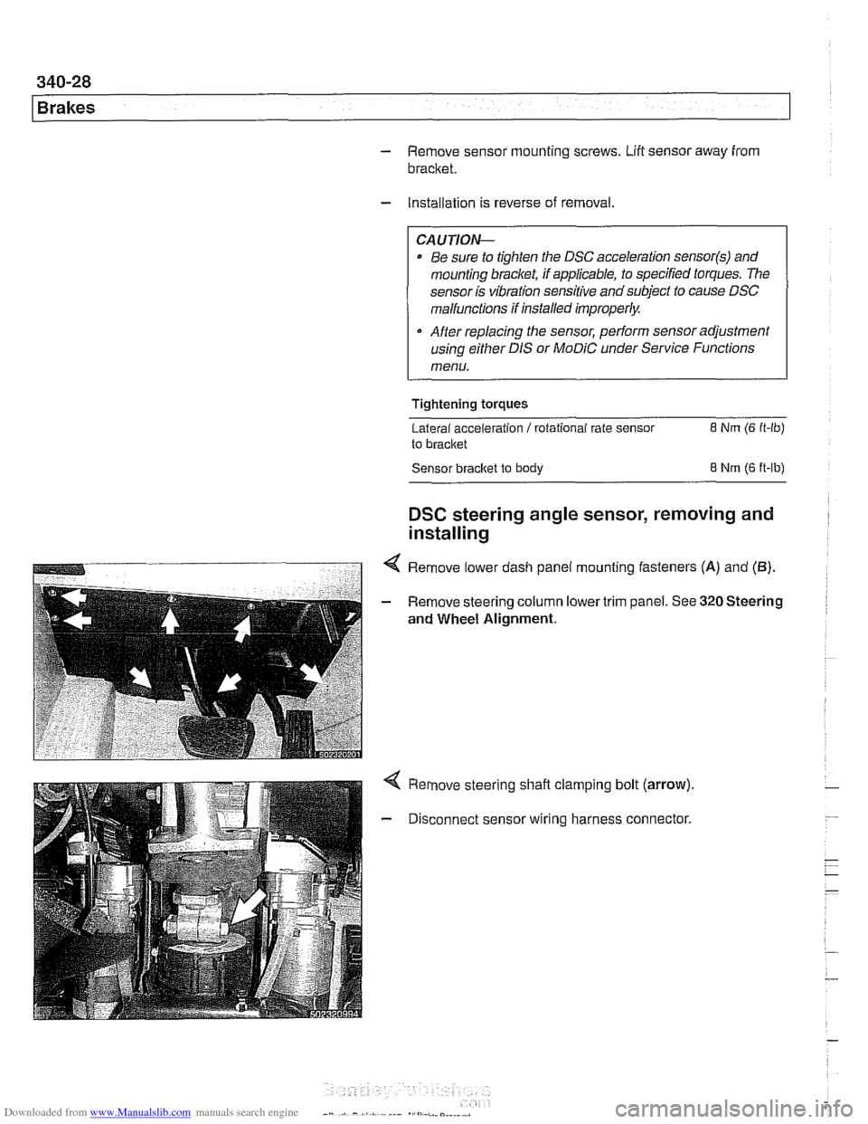
4 Remove lower dash panel mounting fasteners (A) and (5).
- Remove steering column lower trim panel. See 320 Steering
and Wheel Alignment.
Remove steering shaft clamping bolt (arrow).
Disconnect sensor wiring harness connector.
Page 819 of 1002
Downloaded from www.Manualslib.com manuals search engine
General ........................... .41 1.2 Door hinge adjustment ................ 41 1-5
Door hinge assembly
.................. 41 1-6 Doors ............................. 411-2
Front or rear door. removing
Door Panels ....................... 41 1-7
and installing ....................... .41 1.2 Door trim panel. removing and installing ... 41 1-7
Door check. replacing
................. .41 1.4 Sill trim panels ...................... 41 1-1 0
Page 822 of 1002
Downloaded from www.Manualslib.com manuals search engine
Doors
~obr adjustment
Front fender to
4.25 mm i 0.25 mm (0.17 i- 0.01 in)
front door gap
Front
door to 4.5 mm i 0.25 mm (0.18 i 0.01 in)
rear door gap
Rear door to rear fender 4.0 mm i 0.25 mm (0.16 i 0.01 in)
Permissible deviation 1 .O mm (0.04 in)
from
~arallel
Tightening torque
Door hinge to door frame
20 Nm (15 it-lb)
Door check, replacing
WARNING -
E39 cars are fitted with side-impact airbags in the front doors
and optional side impact
airbags in the rear doors. When
servicing doors, always disconnect the negative
(-) battery
terminal. See
721 Airbag System (SRS) for cautions and
procedures relating to the
airbag system.
- Close door window completely.
- Disconnect negative (-) battery cable.
CAUTION-
Prior to disconnecting the batter)! read the battery discon-
nection cautions given in
001 General Cautions and
Warnings.
- Remove interior door panel. See Door trim panels, remov-
ing and installing.
- Where applicable, remove side-impact airbag from door. See
721 Airbag System (SRS). Remove door vapor barrier.
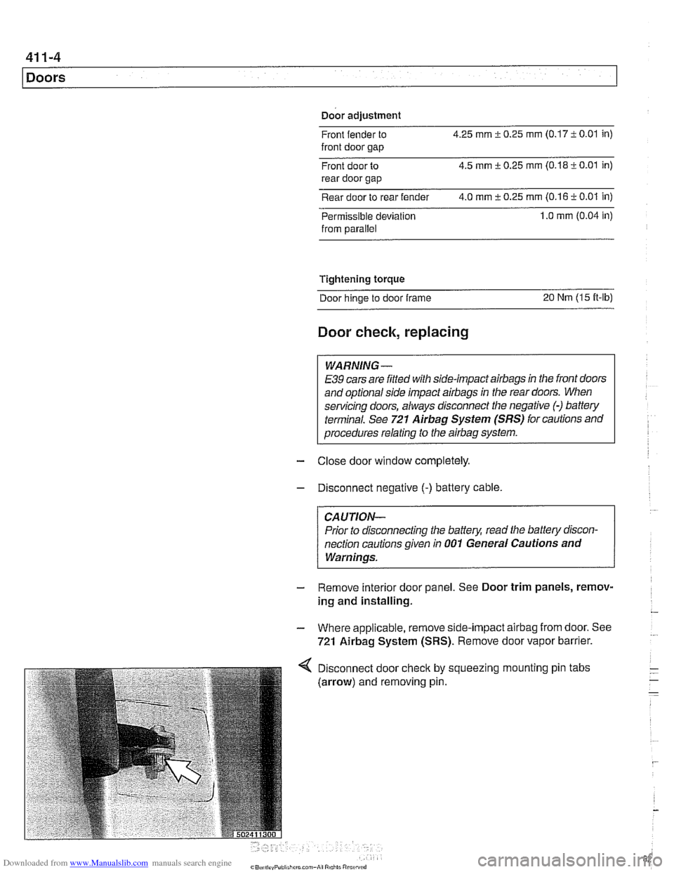
Disconnect door
check by
(arrow) and removing pin. squeezing I mounting
pin tabs
Page 851 of 1002
Downloaded from www.Manualslib.com manuals search engine
51 0 Exterior Trim. Bumpers
General ........................... .51 0.2 Exterior Trim ...................... 51 0-1 3
Outside Rear View Mirrors
Outside mirror glass. replacing
Outside mirror housing.
removing and installing
......
Outside mirror assemblv .
BMW emblem. removing and installing ... 510-13 .......... .51 0.2
Body side molding. replacing ........... 51 0-13 .......... .51 0.2
Radiator grill. removing and installing .... 51 0-1 4
Headlight housing trim panel.
.......... .51 0.3
removing and installing ............... 510-14 . .
removing and installing ................ .51 0.4
Bumpers ......................... .51 0.5
Front bumper assembly
............... .51 0.6
Front bumper, removing and installing
.... .51 0.7
Front bumper impact absorber. replacing
. .51 0.8
Rear bumper assembly ............... .51 0.9
Rear bumper. removing and installing
... .51 0.10
Rear bumper impact absorber. replacing
. .51 0.1 1
Front bumper height. adjusting
......... .51 0.12
Page 852 of 1002
Downloaded from www.Manualslib.com manuals search engine
-
Exterior Trim, Bumpers
This repair group includes repair information for the outside
rearview mirrors, front and rear bumpers, and the easily re-
movable exterior trim parts.
Many of the mirror components are separately available from
an authorized
BMW dealer, including the glass and outside .
plastic housing.
The
E39 models offered two types of outside mirrors, stan-
dard mirrors or automatic dip mirrors.
Outside mirror glass, replacing
CAUTIOI\C
Mirrorshould be at or above room temperature before remov-
al.
Othe~lise, small plastic parfs or glass may break.
Outside mirror glass without automatic dip control,
replacing
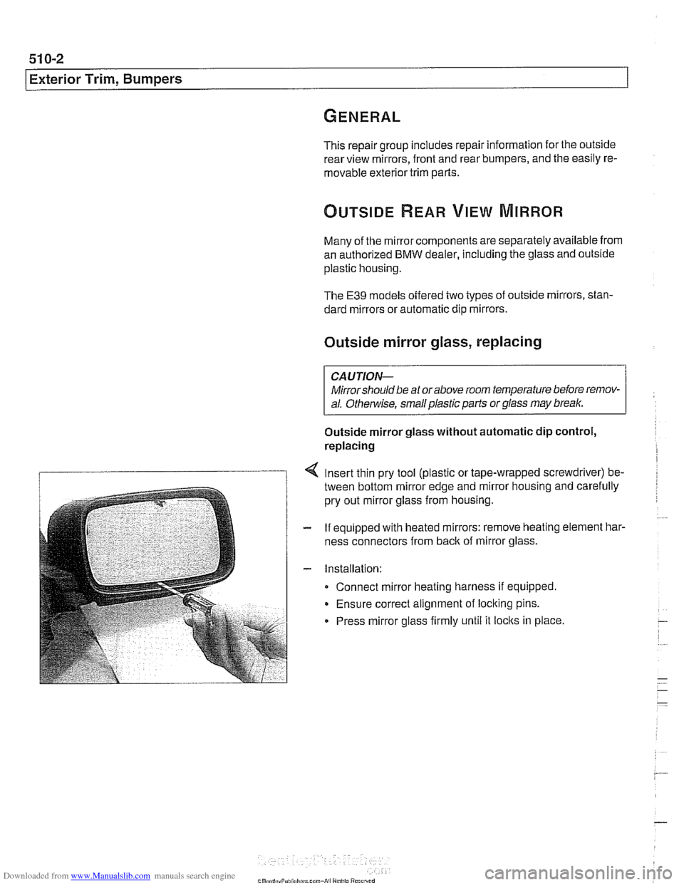
Insert thin pry tool (plastic or tape-wrapped screwdriver) be-
tween bottom mirror edge and mirror housing and carefully
pry out mirror glass from housing.
If equipped with heated mirrors: remove heating element
har.
ness connectors from back of mirror glass.
Installation: Connect mirror heating harness if equipped.
Ensure correct alignment of locking pins.
Press mirror glass firmly until it
locks in place.
Page 853 of 1002
Downloaded from www.Manualslib.com manuals search engine
-.- -
Exterior Trim, Bumpers
Outside mirror glass with automatic dip control,
replacing
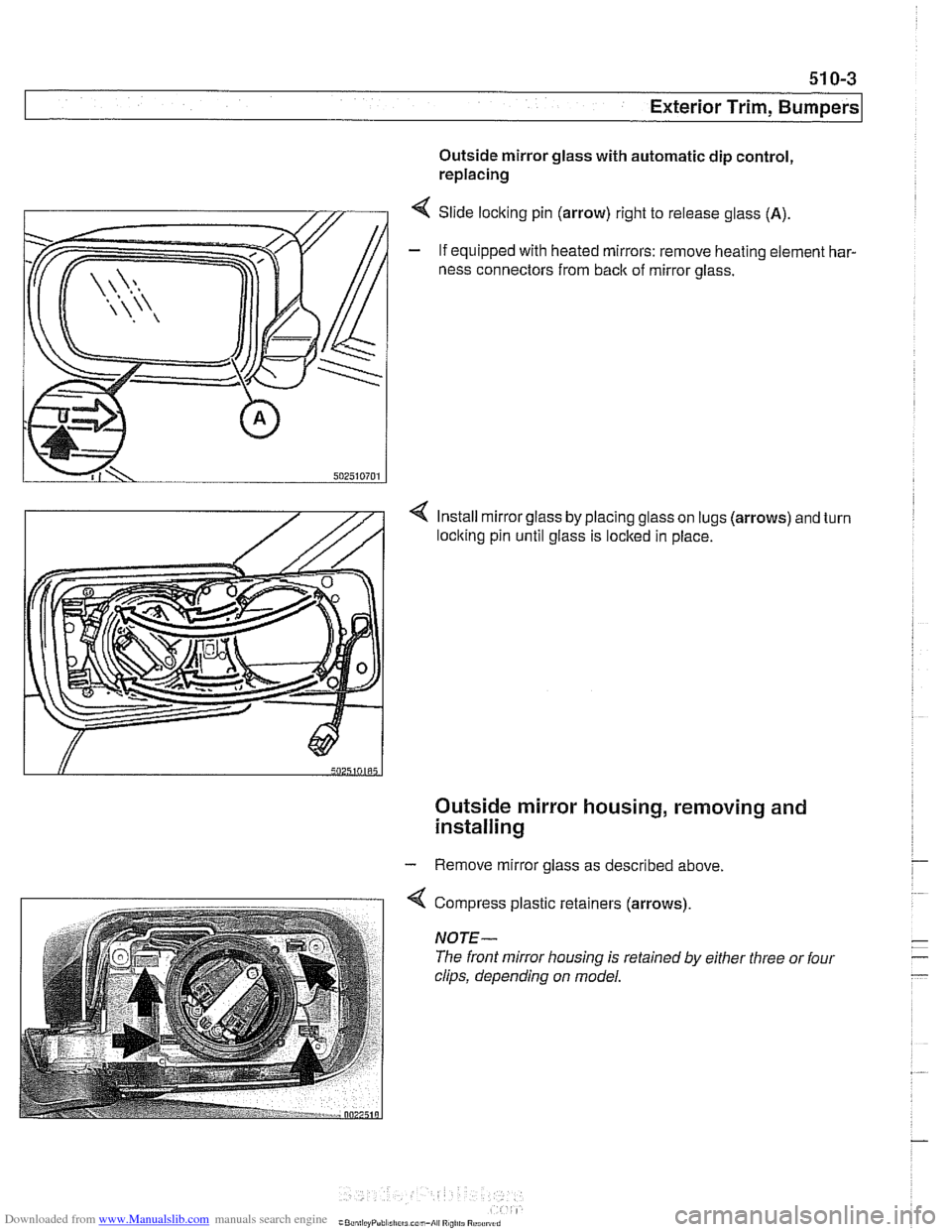
4 Slide locking pin (arrow) right to release glass (A).
- If equipped with heated mirrors: remove heating element har-
ness connectors from
back of mirror glass.
4 Install mirror glass by placing glass on lugs (arrows) and turn
loclting pin until glass is locked in place.
Outside mirror housing, removing and
installing
- Remove mirror glass as described above.
4 Compress plastic retainers (arrows)
NOTE-
The front mirror housing is retained by either three or four
clips, depending on model.
Page 858 of 1002
Downloaded from www.Manualslib.com manuals search engine
51 0-8
I Exterior Trim, Bumpers
- Installation is reverse of removal, noting the following:
Carefully slide bumper side panels over mounting brackets
on fenders.
Make sure gap between body and bumper is set to speci-
fications. Adjust height as necessary. See Front bumper
height, adjusting.
If equipped with headlight washers or
park distance control
reconnect hoses and harness.
Tightening torque Bumper to impact absorber
(M10) 41 Nm (30 ft-lb)
Front bumper impact absorber, replacing
To access front bumper mounting bracket and impact absorb-
er mounting hardware remove front bumper cover. See Front
bumper, removing and installing.
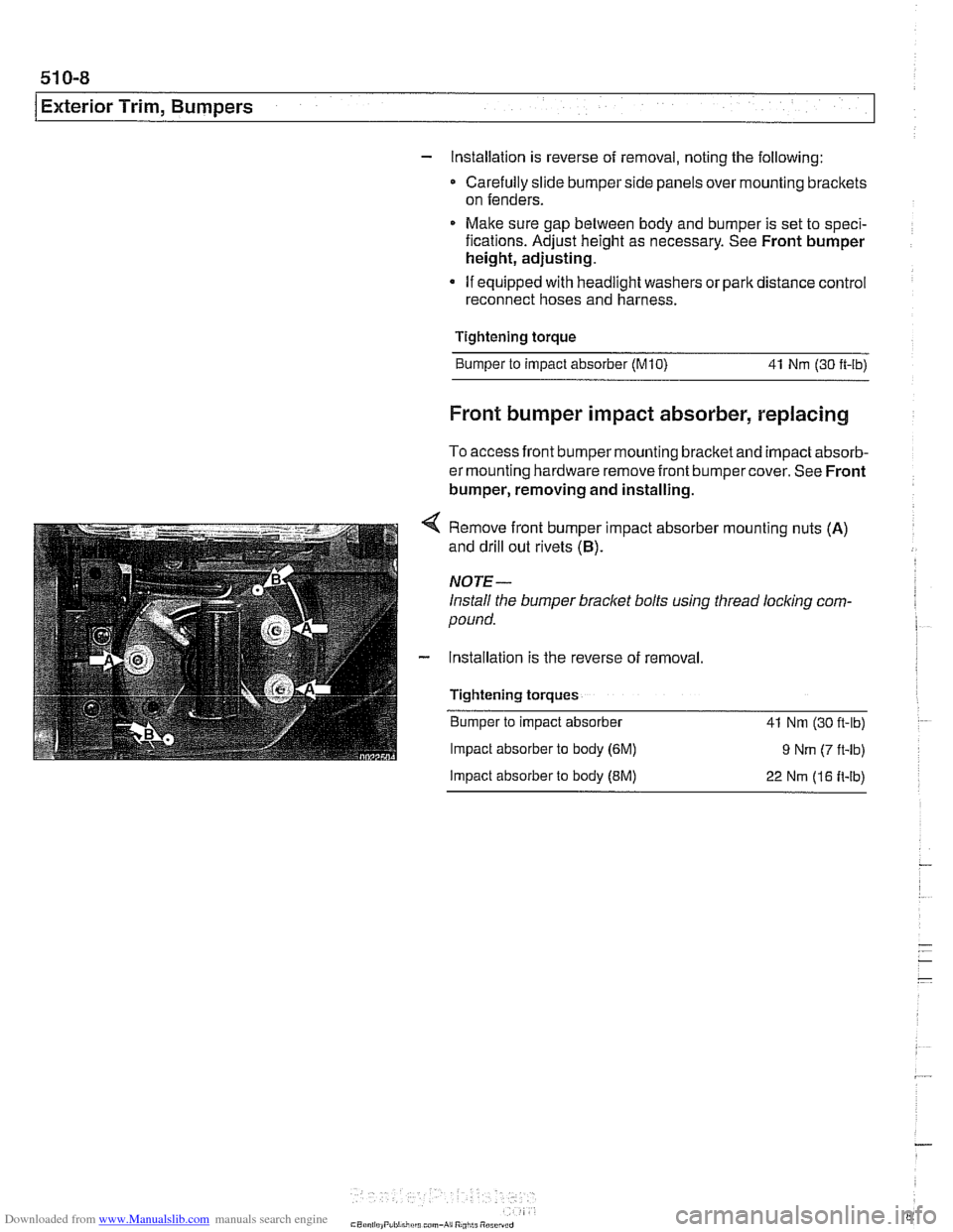
4 Remove front bumper impact absorber mounting nuts (A)
and drill out rivets (B).
NOTE-
Install the bumper bracket bolts using thread locking com-
pound.
- Installation is the reverse of removal.
Tightening torques Bumper to impact absorber
41 Nm (30 fl-lb)
Impact absorber to body (6M) 9 Nm (7 ft-lb)
Impact absorber to body (EM) 22 Nm (16 It-lb)
Page 861 of 1002
Downloaded from www.Manualslib.com manuals search engine
Exterior Trim, Bumpers
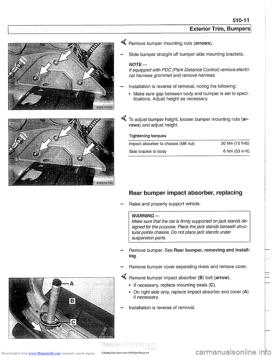
4 Remove bumper mounting nuts (arrows)
- Slide bumper straight off bumper side mounting brackets.
NOTE-
If equipped with PDC (Park Distance Control) remove electri-
cal harness grommet and remove harness.
- lnstallation is reverse of removal, noting the following:
Make sure gap between body and bumper is set to speci-
fications. Adjust height as necessary.
To adjust bumper height, loosen bumper mounting nuts (ar-
rows) and adjust height.
Tightening torques
Impact absorber to chassis (ME nut) 20 Nm (15 ft-lb)
Side bracket to body 6 Nm (53 in-it)
Rear bumper impact absorber, replacing
- Raise and properly support vehicle.
WARNING -
Make sure that the car is firmly supported on jack stands de-
signed for the purpose. Place the jack stands beneath
struc-
turalpoints chassis. Do not place jaclc stands under
suspension parts.
- Remove bumper. See Rear bumper, removing and install-
ing.
- Remove bumper cover expanding rivets and remove cover.
. - . . - . . ".-- < Remove b~mper mpact absorber (6) bot (arrow).
I If necessary, replace mounting seals (C).
- Installation is reverse of removal.
Page 863 of 1002
Downloaded from www.Manualslib.com manuals search engine
51 0-1 3
Exterior Trim, Bumpers
Exterior trim is attached to the body with plastic clips and fas-
teners that may be damaged during removal. Be sure to have
necessary fasteners on hand when reinstalling exterior trim
pieces.
BMW emblem, removing and installing
The procedure given below applies to both front and rear
emblems.
- Wrap end of a screwdriver with tape.
CAUTION-
Protect hood paint by covering area around emblem with
tape.
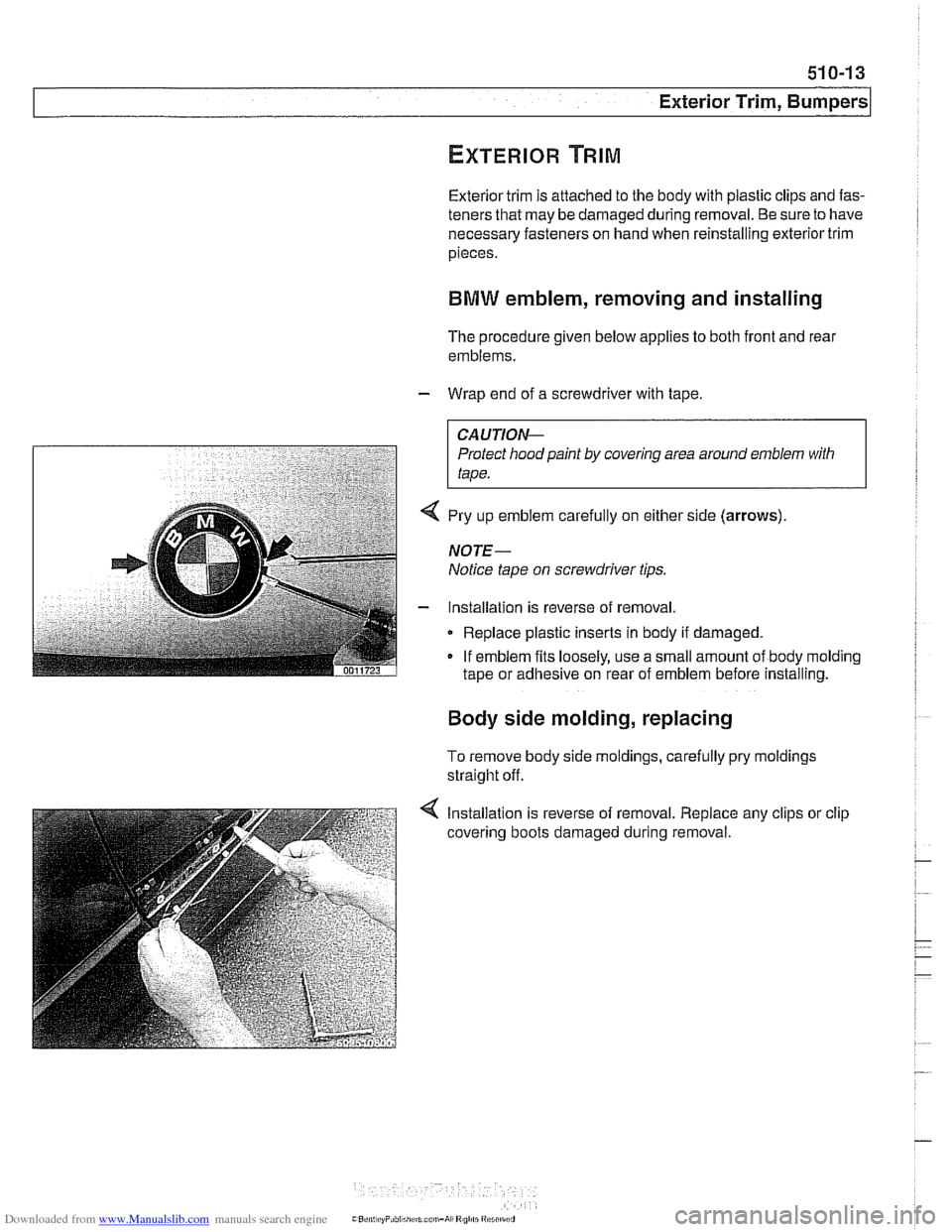
4 Pry up emblem carefully on either side (arrows)
NOTE-
Notice tape on screwdriver tips.
- Installation is reverse of removal
Replace plastic inserts in body if damaged.
If emblem fits loosely, use a small amount of body molding
tape or adhesive on rear of emblem before installing.
Body side molding, replacing
To remove body side moldings, carefully pry moldings
straight off.
4 Installation is reverse of removal. Replace any clips or clip
covering boots damaged during removal.
Page 871 of 1002
Downloaded from www.Manualslib.com manuals search engine
Door Windows
molding and
anti-trap strip
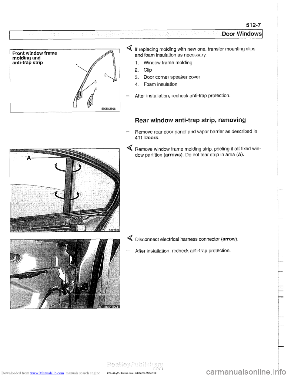
4 If replacing molding with new one, transfer mounting clips
and foam insulation as necessary.
1. Window frame molding
2. Clip
3. Door corner speaker cover
4. Foam insulation
- After installation, recheck anti-trap protection.
Rear window anti-trap strip, removing
- Remove rear door panel and vapor barrier as described in
411 Doors.
4 Remove window frame molding strip, peeling it off fixed win-
dow partition
(arrows). Do not tear strip in area (A).
Disconnect electrical harness connector (arrow).
After installation, recheck anti-trap protection.