replacing BMW 540i 1997 E39 Owners Manual
[x] Cancel search | Manufacturer: BMW, Model Year: 1997, Model line: 540i, Model: BMW 540i 1997 E39Pages: 1002
Page 618 of 1002
Downloaded from www.Manualslib.com manuals search engine
260-1 2
1 Driveshaft
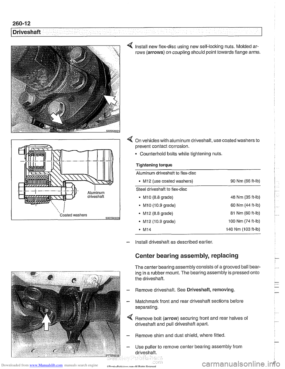
Install new flex-disc using new self-locking nuts. Molded ar-
rows (arrows) on coupling should point towards flange arms.
4 On vehicles with aluminum driveshaft, use coated washers to
prevent contact corrosion.
- Counterhold bolts while tightening nuts.
Tightening torque
Aluminum driveshaft to flex-disc
M12 (use coated washers) 90
Nm (66 ft-lb)
Steel driveshaft to flex-disc
MI0 (8.8 grade) 48
Nm (35 ft-lb)
- MI0 (10.9 grade) 60 Nm (44 ft-lb)
Coated washers - MI2 (8.8 grade) 5027500 . Mi2 (10.9 grade)
M14 81
Nm (60 ft-lb) 100 Nm (74 ft-lb)
140 Nm (103 ft-lb)
- Install driveshaft as described earlier
Center bearing assembly, replacing
The center bearing assembly consists of a grooved ball bear-
ing in a rubber mount. The bearing assembly is pressed
the driveshaft.
- Remove driveshaft. See Driveshaft, removing
- Matchmark front and rear driveshaft sections before
separating.
Remove bolt (arrow) securing front and rear halves of
driveshaft and pull driveshaft apart.
- Remove shim and dust shield, where fitted
- Use puller to remove center bearing assembly from
driveshaft. onto
Page 619 of 1002
Downloaded from www.Manualslib.com manuals search engine
- On installation, drive new center bearing firmly to stop.
Reassemble driveshaft using matchmarks made prior to
disassembly.
- Clean threads and install bolt securing driveshaft halves.
Use thread locking compound
LoctiteO or equivalent.
Tightening torque Driveshaft front half to rear half
(use thread locking compound) 97
Nm (72 fl-lb)
- Install driveshaft as described earlier.
Front centering guide, replacing
The front centering guide centers the driveshafl in relation to
the transmission. The guide is press-fit into a cavity in the
front of the driveshafl and slides onto the transmission output
shaft.
No specifications are given
forwear of the guide, but general-
ly the guide should fit snugly on the transmission output shafl.
NOTE-
Some driveshafts have a dust cap installed on the end of the
driveshaft, over the centering guide. The dust cap may be-
come bent or distorted when the driveshaft is removed or
in-
stalled. Damage to the dust cap should not affect the
centering guide and should not be mistaken for guide wear.
- Remove driveshafl as described earlier
- Pack cavity behind centering guide with heavy grease until
grease is flush with bottom edge of guide.
- Insert 14 mm (approximately 9/16 in.) diameter mandrel or
metal rod into guide. Strike guide with hammer to force cen-
tering guide out.
NOTE-
Tlie mandrel should fit snugly in the centering guide so that
the grease cannot escape around the sides of the mandrel.
- Remove old grease from driveshaft, lubricate new centering
guide with molybdenum disulfide grease
(MolykoteO, Long-
term8 2 or equivalent) and drive it into driveshaft.
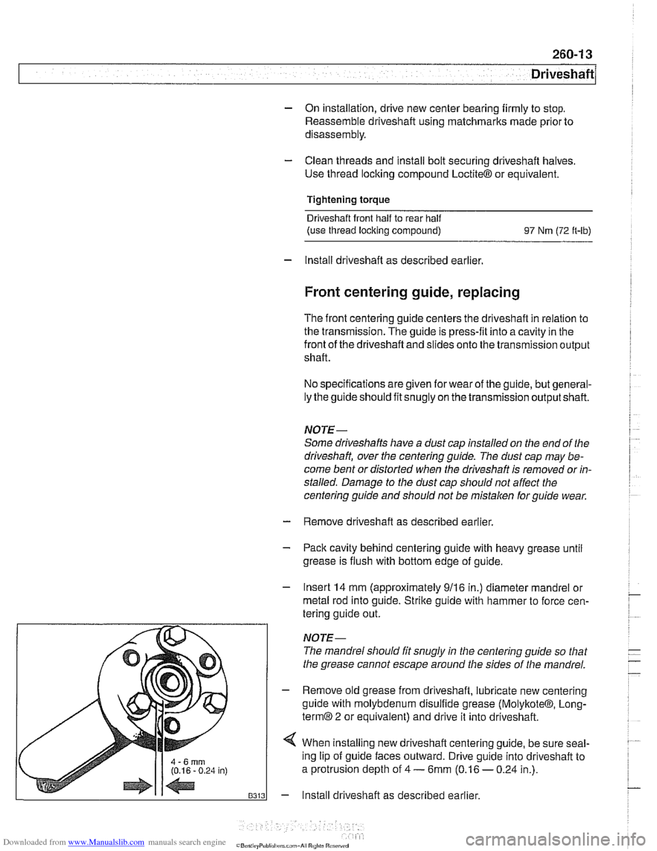
4 When installing new driveshafl centering guide, be sure seal-
ing lip of guide faces outward. Drive guide into driveshaft to
a protrusion depth of
4 - 6mm (0.16 - 0.24 in.).
- Install driveshaft as described earlier.
Page 620 of 1002
Downloaded from www.Manualslib.com manuals search engine
260-14
Driveshaft
Constant velocity (CV) joint, replacing
The CV joint at the rear of the driveshaft is available from
BMW as a separate part.
- Remove complete driveshaft as described earlier in this
section.
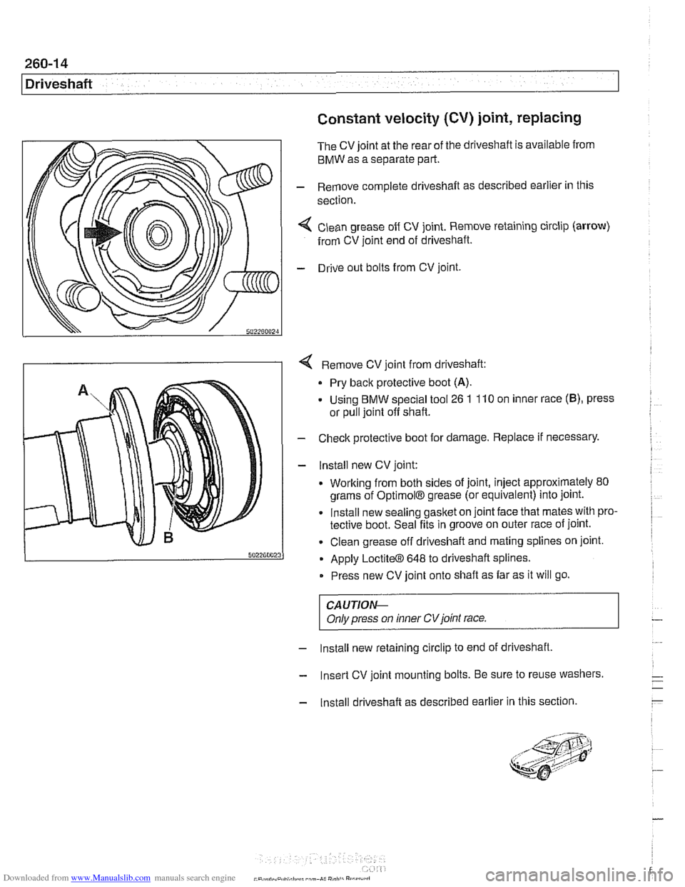
< Clean grease off CV joint. Remove retaining circlip (arrow)
from CV joint end of driveshaft.
- Drive out bolts from CV joint.
4 Remove CV joint from driveshaft:
Pry back protective boot
(A).
- Using BMW special tool 26 1 110 on inner race (B), press
or pull joint off shaft.
- Check protective boot for damage. Replace if necessary.
- lnstall new CV joint:
. Working from both sides of joint, inject approximately 80
grams of
OptimolB grease (or equivalent) into joint.
Install new sealing gasket on joint face that mates with pro-
tective boot. Seal fits in groove on outer race of joint.
Clean grease off driveshaft and mating splines on joint.
Apply
LoctiteO 648 to driveshaft splines.
Press new CV joint onto shaft as far as it will go.
CAUTIOI\C
Only press on inner CVjoint race.
- Install new retaining circlip to end of driveshaft,
- Insert CV joint mounting bolts. Be sure to reuse washers.
- Install driveshaft as described earlier in this section.
Page 637 of 1002
Downloaded from www.Manualslib.com manuals search engine
31 0 Front Suspension
General . . . . . . . . . . . . . . . . . . . . . . . . . . . .310-2 Front Suspension Arms . . . . . . . . . . . 310-1 2
Special tools . . . . . . . . . . . . . . . . . . . . . . . . ,310-2 Control arm, removing and installing
Front suspension variations
. . . . . . . . . . . . ,310-4 (6-cylinder models) . . . . . . . . . . . . . . . . . . 31 0-1 2
Control arm, removing and installing Front Strut ' ' ' ' ' ' ' ' ' ' ' ' ' ' '310-4 ("-8 models) , , , , , , , , , , , , , , , , , , , , , , , 310-13 Front strut assembly, removing
Tension strut, removing and installing . . . . 310-16 and installing . . . . . . . . . . . . . . . . . . . . . . . . ,310-5 Tension strut bushing, replacing . . . . . . . . 310-18 Front strut assembly components
(6-cylinder models)
. . . . . . . . . . . . . . . . . . ,310-9 Wheel Bearings, Front . . . . . . . . . . . . . 310-18
iron; strut assembly, disassembling Front Stabilizer Bar . . . . . . . . . . . . . . . 310-22 and assembling . . . . . . . . . . . . . . . . . . . . . ,310-9 Stabilizer bar, removing and installing . . . . 310-22
Page 645 of 1002
Downloaded from www.Manualslib.com manuals search engine
31 0-9
Front Suspension
Front strut assembly
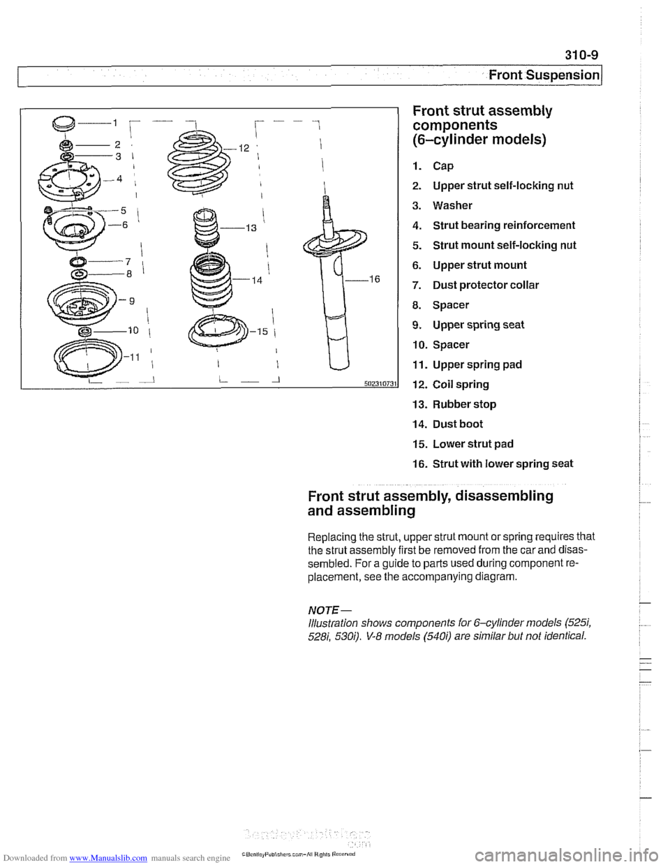
components
(6-cylinder models)
1. Cap
2. Upper strut self-locking nut
3. Washer
4. Strut bearing reinforcement
5. Strut mount self-locking nut
6. Upper strut mount
7. Dust protector collar
8. Spacer
9. Upper spring seat
10. Spacer
11. Upper spring pad
12. Coil spring
13. Rubber stop
14. Dust boot
15. Lower strut pad
16. Strut with lower spring seat
Front strut assembly, disassembling
and assembling
Replacing the strut, upper strut mount or spring requires that
the strut assembly first be removed from the car
and disas-
sembled. For a guide to parts used during component re-
placement, see the accompanying diagram.
NOTE-
Illustration shows components ior 6-cylinder models (525i,
528i, 530;). V-8 models (540i) are similar but not identical.
Page 654 of 1002
Downloaded from www.Manualslib.com manuals search engine
31 0-1 8
I~ront Suspension Tension strut bushing, replacing
- Raise car and remove wheel.
WARNING-
Make sure that the caris firmly supported on jack stands de-
signed for the purpose. Place jack stands underneath struc-
tural chassis points. Do
not place jack stands under
suspension parts.
- Remove tension strut from car as described earlier.
- Using a service press and appropriate press tools (BMW
special tools 31 2 26112621263 or equivalent), press bushing
out of tension strut.
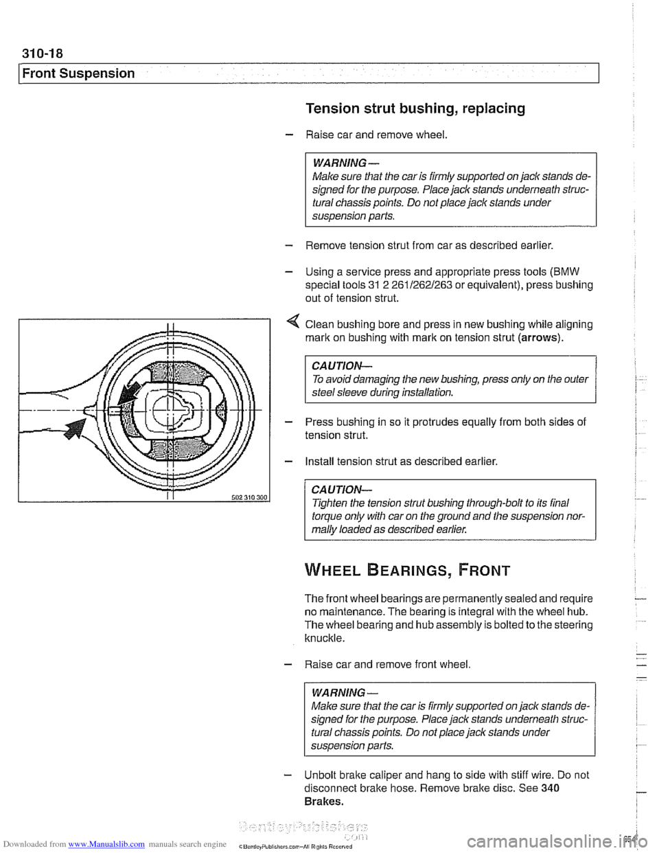
4 Clean bushing bore and press in new bushing while aligning
mark on bushing with
rnarlt on tension strut (arrows).
CAUTION-
To avoid damaging the new bushing, press only on the outer
steel sleeve during installation.
- Press bushing in so it protrudes equally from both sides of
tension strut.
- Install tension strut as described earlier.
CAUTION-
Tighten the tension strut bushing through-bolt to its final
torque only with car on the ground and the suspension nor-
mally loaded as described earlier.
The front wheel bearings are permanently sealed and require
no maintenance. The bearing is integral with the wheel hub.
The wheel bearing and hub assembly is bolted to the steering
knuckle.
- Raise car and remove front wheel
WARNING-
Make sure that the car is firmly supported on jack stands de-
signed for the purpose. Place jack stands underneath struc-
tural chassis points. Do not place
jack stands under
susoension Darts.
- Unbolt brake caliper and hang to side with stiff wire. Do not
disconnect bralte hose. Remove bralte disc. See
340
Brakes.
Page 659 of 1002
Downloaded from www.Manualslib.com manuals search engine
1 320 Steering and Wheel Alignment
General ........................... .32 0.2
Special tools
........................ .32 0.2
Steering system
..................... .32 0.4
Steering system variations
............. .32 0.5
Steering system warnings and cautions
... .32 0.6
Steering Wheel .................... .32 0.7
Steering wheel. removal and installation
.. .32 0.7
Steering Column ................. .32 0.1 0
Steering column components .......... .32 0.10
Steering column trim, removing
and replacing
...................... .32 0.10
lgnition switch ring antenna (EWS).
removing and installing
............... .32 0.1 1
lgnition lock cylinder.
removing and installing
............... .32 0-1 1
Steering column lock. removing
and installing
....................... .32 0.12
lgnition
interloclc cable. removing and installing
(models with automatic transmission)
... .32 0.13
Interlock cable. adjusting
(models with automatic transmission)
... .32 0.14
Steering column. removing and installing
. .32 0.14
Steering column adjustment motors.
removing and installing
............... .32 0.16
Power Steering Pump ............. .32 0.17
Power steering pump. removing
and installing
....................... .32 0.1 7
Power steering system.
bleeding and filling
.................. .32 0.18
Rack and Pinion Steering
(6-cylinder models)
............... 320-19
Rack and pinion steering components
(6-cylinder models)
.................. 320-1 9
Steering rack. removing and installing
.... 320-19
Steering
rack boot. replacing ........... 320-22
Tie rod (outer). replacing
.............. 320-22
Tie rod (inner). replacing
.............. 320-23
Steering Gearbox (V-8 models) .... 320-24
Steering gearbox system components
. .
(V-8 models) ....................... 320-24
Steering gearbox, removing and installing 320-25
Pitman arm. removing and installing ..... 320-28
Pitman arm. adjusting ................ 320-29
Steering idler arm. removing
and installing
....................... 320-30
Idler arm bushing. replacing ........... 320-31
Center tie rod. replacing
.............. 320-32
Wheel Alignment .................. 320-33
Camber
........................... 320-33
Caster
............................ 320-33
Front toe and toe difference angle
....... 320-34
Reartoe ........................... 320-34
Preparing for alignment
............... 320-35
Alignment specifications tables
......... 320-35
Page 667 of 1002
Downloaded from www.Manualslib.com manuals search engine
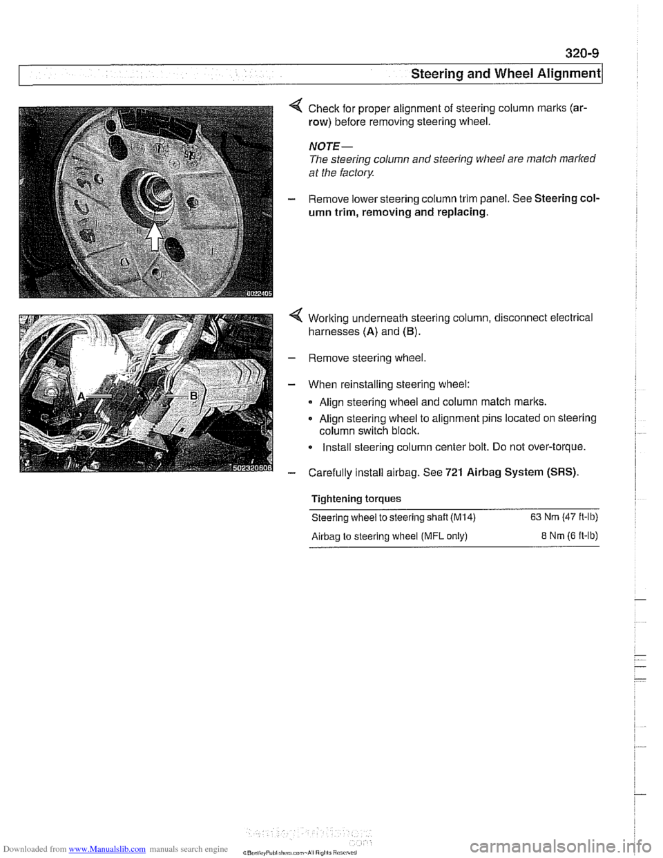
Check for proper alignment of steering column marks (ar-
row) before removing steering wheel.
NOTE-
The steering column and steering wheel are match marked
at the factory
Remove lower steering column trim panel. See Steering col-
umn trim, removing
and replacing.
Working underneath steering column, disconnect electrical
harnesses (A) and
(B).
Remove steering wheel.
When reinstalling steering wheel:
Align steering wheel and column match
marks.
Align steering wheel to alignment pins located on steering
column switch block.
Install steering column center bolt. Do not over-torque.
Carefully install
airbag. See 721 Airbag System (SRS).
Tightening torques
Steering wheel to steering
shaft (M14) 63 Nm (47 ft-lb)
Airbag to steering wheel (MFL only) 8 Nm (6 ft-lb)
Page 668 of 1002
Downloaded from www.Manualslib.com manuals search engine
320-1 0
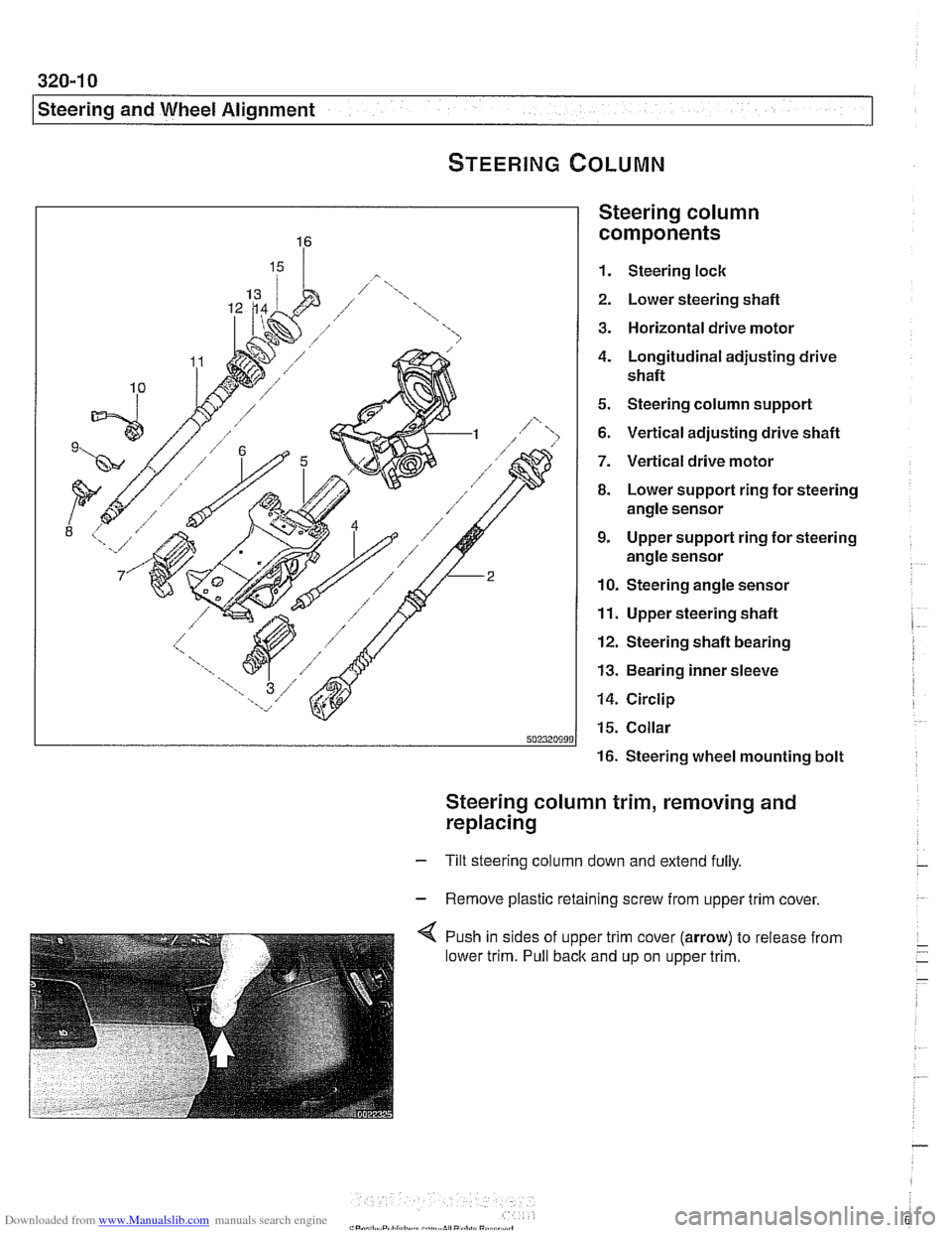
Steering and Wheel Alignment
Steering column
components
1. Steering lock
2. Lower steering shafl
3. Horizontal drive motor
4. Longitudinal adjusting drive
shafl
5. Steering column support
6. Vertical adjusting drive shafl
7. Vertical drive motor
8. Lower support ring for steering
angle sensor
9. Upper support ring for steering
angle sensor
10. Steering angle sensor
11. Upper steering shafl
12. Steering shafl bearing
13. Bearing inner sleeve
14. Circlip
15. Collar
16. Steering wheel mounting bolt
Steering column trim, removing and
replacing
- Tilt steering column down and extend fully.
- Remove plastic retaining screw from upper trim cover,
4 Push in sides of upper trim cover (arrow) to release from
lower trim. Pull back and up on upper trim.
Page 674 of 1002
Downloaded from www.Manualslib.com manuals search engine
I Steering and Wheel Alignment
- Installation is reverse of removal, noting the following:
Replace shear bolts at steering column mounting bracket.
Tighten until bolt heads shear off.
Make sure
interlock cable snaps into place.
When installing column top trim panel, replace expansion
nut for trim retaining screw.
NOTE-
The steering angle sensor must be coded using a BMW scan
tool if it has been replaced.
A steering angle offset check
must then be carried out using the same
BMW scan tool.
CAUTION-
Check steering system for freedom of movement through en-
tire steering column
adiustment range.
Tightening torques Steering shaft coupler
to steering shaft 25 Nm (18 ft-lb)
(replace bolt)
Steering column to body
22 Nm (16 ft-lb)
Steering column adjustment motors,
removing and installing
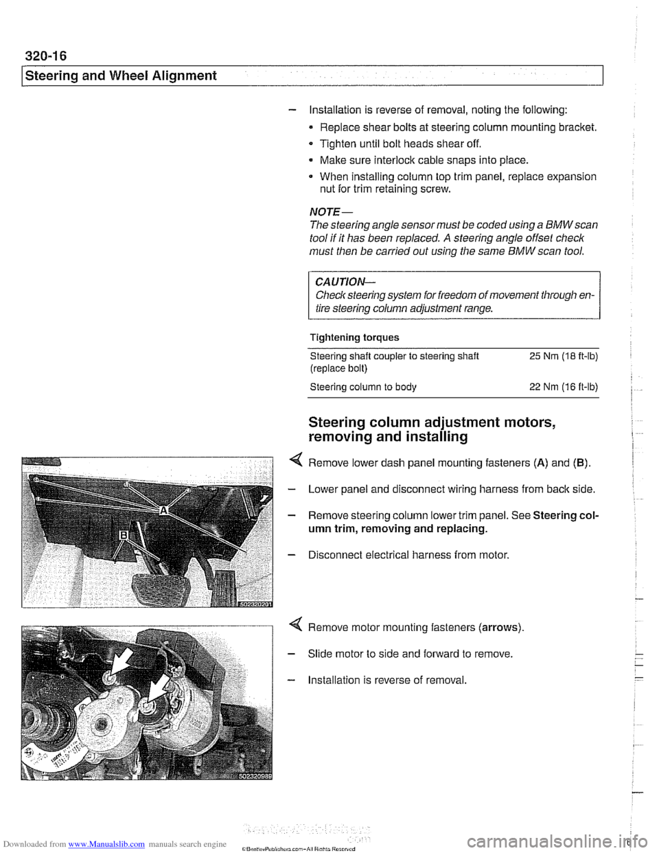
Remove lower dash panel mounting fasteners (A) and (B).
- Lower panel and disconnect wiring harness from back side.
- Remove steering column lower trim panel. See Steering col-
umn trim, removing and replacing.
- Disconnect electrical harness from motor.
Remove motor mounting fasteners (arrows)
Slide motor to side and forward to remove.
Installation is reverse of removal.