replacing BMW 540i 1997 E39 Workshop Manual
[x] Cancel search | Manufacturer: BMW, Model Year: 1997, Model line: 540i, Model: BMW 540i 1997 E39Pages: 1002
Page 680 of 1002
Downloaded from www.Manualslib.com manuals search engine
--. --
Steering and Wheel Alignment
Steering rack boot, replacing
- Remove outer tie rod end. See Tie rod (outer), replacing
- Cut rack boot band clamps and remove boot.
- Cut rack boot band clamp and slide bellows back. Inspect
boot for any sign of damage. Replace
if necessary.
NOTE-
New rack boot lit comes with new band clamp.
- Grease tie rod taper so that small end of rack boot slides on
tie rod when tie rod is tightened, preventing raclc boot from
twisting.
- Slide new boot into position and replace band clamps
Tie rod (outer), replacing
LOCI( nut Locking ring
- Raise front of car. Remove road wheel
WARNING-
Male sure caris firmly suppoiiedon jackstands designed for
the purpose. Place jack stands beneath structural chassis
ooints. Do not olace iack stands under
susoension oaiis.
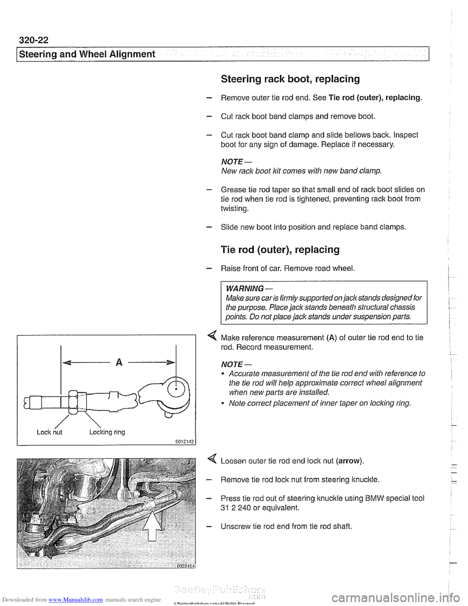
4 Make reference measurement (A) of outer tie rod end to tie
rod. Record measurement.
NOTE-
Accurate measurement of the tie rod end with reference to
the tie rod will help approximate correct
wheel alignment
when new parts are installed.
Note correct placement of inner taper on
loclcing ring.
Loosen outer tie rod end
loclc nut (arrow).
Remove tie rod lock nut from steering
ltnuclcle.
Press tie rod out of steering knuckle using BMW
31 2 240 or equivalent. special tool
Unscrew tie rod end from tie rod shaft.
Page 681 of 1002
Downloaded from www.Manualslib.com manuals search engine
Steering and Wheel Alignment
- lnstallation is reverse of removal.
Make sure all threaded parts are clean.
Use anti-seize paste on inner tie rod threads.
Use new self-locking nuts, where applicable.
Use tie rod measurement
(A) to set toe temporarily.
Have car professionally aligned.
Tightening torque
Tie rod
to steering itnuckle (replace seii-loclting nut) 65 Nm ( 46 ft-lb)
Outer tie rod end ioclt nut 51 Nm (38 ft-ib)
Tie rod (inner), replacing
- To replace inner tie rod, first remove outer tie rod end. See
Tie rod (outer), replacing.
- Cut rack boot clamps and slide bellows back
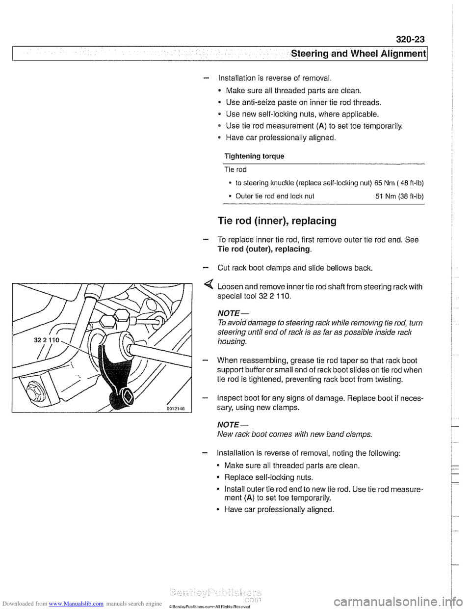
4 Loosen and remove inner tie rod shafl from steering rack with
special tool
32 2 110.
NOTE-
To avoid damage to steering rack while removing tie rod, turn
steering until end of rack is as far as possible inside rack
housing.
- When reassembling, grease tie rod taper so that rack boot
support buffer or small end of rack boot slides on tie rod when
tie rod is tightened, preventing rack boot from twisting.
- Inspect boot for any signs of damage. Replace boot if neces-
sary, using new clamps.
NOTE-
New rack boot comes with new band clamps
- Installation is reverse of removal, noting the following:
Make sure all threaded parts are clean
Replace self-locking nuts.
Install outer tie rod end to new tie rod. Use tie rod measure-
ment
(A) to set toe temporarily.
Have car professionally aligned.
Page 689 of 1002
Downloaded from www.Manualslib.com manuals search engine
320-31
Steering and Wheel ~li~nrnentl
ldler arm bushing, replacing
- Remove idler arm as described earlier.
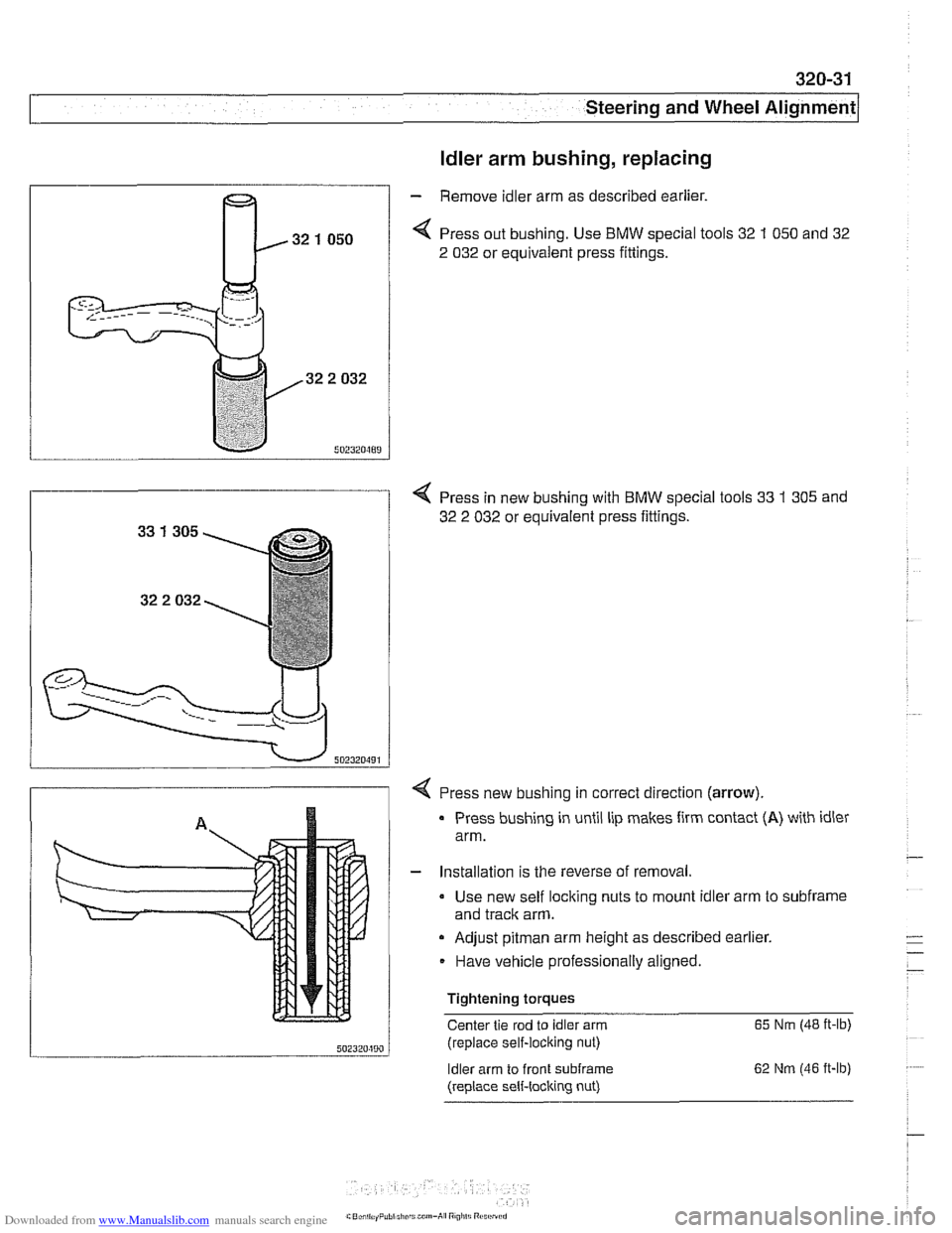
< Press out bushing. Use BMW special tools 32 1 050 and 32
2 032 or equivalent press fittings.
4 Press in new bushing with BMW special tools 33 1 305 and
32 2 032 or equivalent press fittings.
4 Press new bushing in correct direction (arrow).
u ..... "A",
Press bushing in until lip makes firm contact (A) with idler
arm.
I
Installation is the reverse of removal
Use new self locking nuts to mount idler arm to
subframe
and traclc arm.
a Adjust pitman arm height as described earlier.
Have vehicle professionally aligned.
Tightening torques Center tie rod to idler arm
65 Nm (48 ft-lb)
;nl?mmn / (replace self-locking nut)
ldler arm to front
subframe
(replace sell-locking nut) 62
Nm (46 ft-lb)
Page 690 of 1002
Downloaded from www.Manualslib.com manuals search engine
320-32
Steering and Wheel Alignment
Center tie
rod, replacing
- Raise front of car. Remove splash shield from under engine.
WARNING-
Make sure tlie car is firmly supported on jack stands de-
signed for the purpose. Place jack stands beneath structural
cliassis points. Do not place jack stands under suspension
parts.
- Measure length of left and right (outer) tie rods. Write down
measurements.
NOTE-
Accurate measurement of the tie rod end with reference to
the center tie rod will help approximate correct wheel align-
ment when new parts are installed.
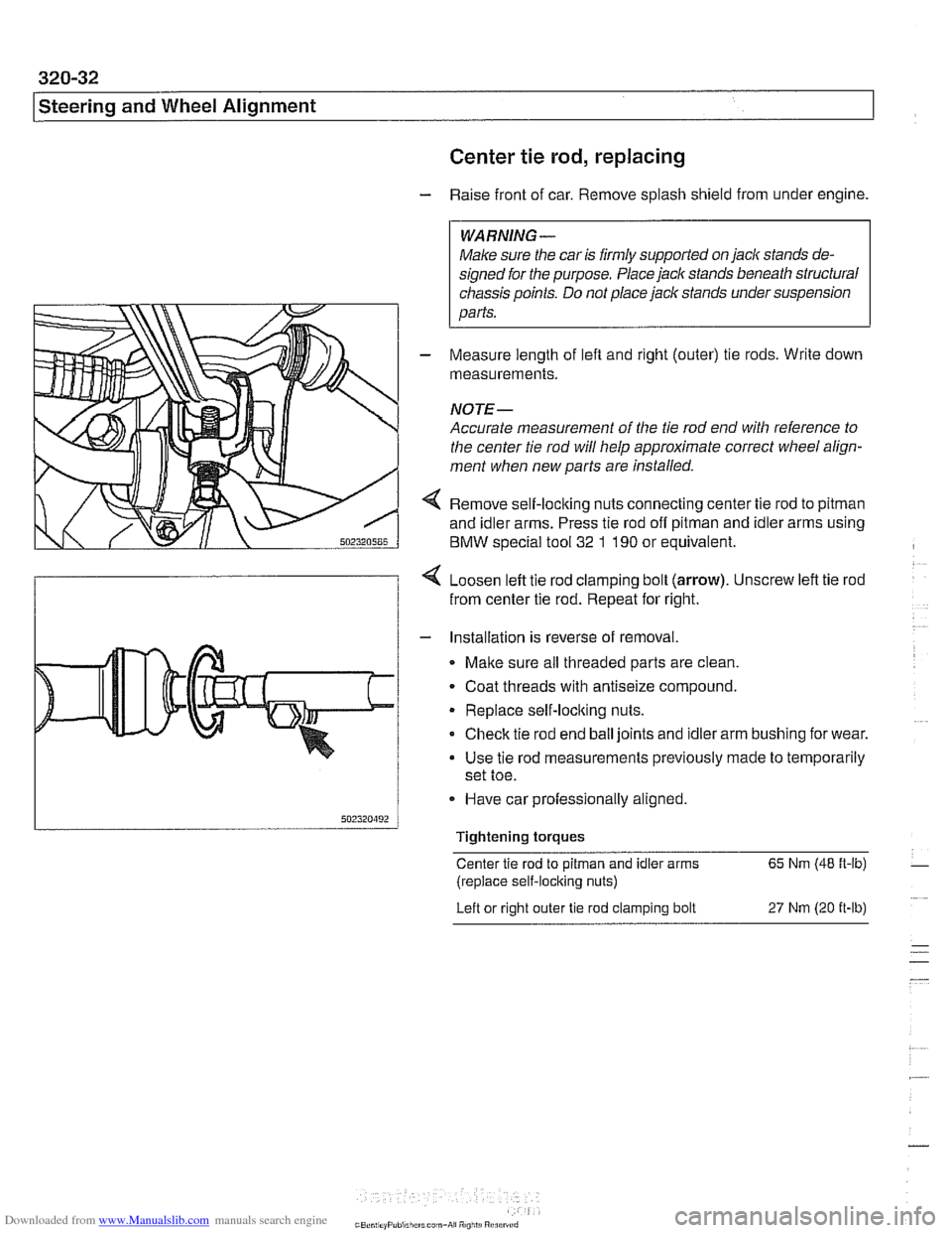
4 Remove self-loclting nuts connecting center tie rod to pitman
and idler arms. Press tie rod off pitman and idler arms using
BMW special tool
32 1 190 or equivalent.
4 Loosen left tie rod clamping bolt (arrow). Unscrew left tie rod
from center tie rod. Repeat for right.
- Installation is reverse of removal.
Malte sure all threaded parts are clean.
. Coat threads with antiseize compound.
Replace self-loclting nuts.
Check tie rod end ball joints and idler arm bushing for wear.
Use tie rod measurements previously made to temporarily
set toe.
- Have car professionally aligned.
Tightening torques
Center tie rod to
pitman and idler arms 65 Nm (48 ft-lb)
(replace self-locking nuts)
Left or right outer
tie rod clamping bolt 27 Nm (20 it-lb)
Page 697 of 1002
Downloaded from www.Manualslib.com manuals search engine
330 Rear Suspension
General . . . . . . . . . . . . . . . . . . . . . . . . . . . ,330-2
Special tools . . . . . . . . . . . . . . . . . . . . . . . . ,330-2
Rear suspension variations . . . . . . . . . . . . ,330-4
Rear Struts and Springs
(sedan models)
. . . . . . . . . . . . . . . . . . . . ,330-5
Rear strut assembly, removing
and installing
. . . . . . . . . . . . . . . . . . . . . . . ,330-5
Rear strut assembly, disassembling
and assembling
. . . . . . . . . . . . . . . . . . . . . ,330-7
Rear Shock Absorbers and
Springs (Sport Wagon models)
. . . . . ,330-9
Rear shock absorber, removing
and installing
. . . . . . . . . . . . . . . . . . . . . . . ,330-9
Coil spring, removing and installing . . . . . ,330-1 1
Air spring, removing and installing
. . . . . . ,330-12
Rear Suspension Arms,
Subframe and Bushings . . . . . . . . . . ,330-13
Rear suspension arm components . . . . . . ,330-1 3
Swing arm, removing and installing (sedan models)
. . . . . . . . . . . . . . . . . . . . . ,330-1 4
Swing arm, removing and installing (Sport Wagon models)
. . . . . . . . . . . . . . . ,330-16
Swing arm ball joint, replacing . . . . . . . . . ,330-1 9
Upper rear control arm, removing
and installing (sedan models)
. . . . . . . . . . .330-22
Upper rear control arm, removing
and installing (Sport Wagon models)
. . . . .330-23
Upper front control arm (traction strut),
removing and installing
. . . . . . . . . . . . . . . ,330-25
Rear axle assembly, removing and
installing (sedan models)
. . . . . . . . . . . . . ,330-26
Rear axle assembly, removing and
installing (Sport Wagon models)
. . . . . . . ,330-28
Rear subframe mounting bushings,
removing and installing
. . . . . . . . . . . . . . . .330-31
Rear Wheel Bearings . . . . . . . . . . .
Rear wheel bearing carrier, removing
and installing (sedan models)
. . . . . . .
Rear wheel bearing carrier, removing
and installing (Sport Wagon models)
. .
Rear wheel bearing, replacing . . . . . . .
Rear Stabilizer Bar
Stabilizer bar, removing and installing .
Stabilizer bar link, removing
and installing
. . . . . . . . . . . . . . . . . . . .
Electronic Height Control (EHC)
Component Replacement
. . . . . . .
Electronic height control (EHC)
components
.....................
Air compressor pump relay, removing
and installing
. . . . . . . . . . . . . . . . . . . .
EHC control module, removing
and installing
. . . . . . . . . . . . . . . . . . . .
Air supply unit, removing and installing
Ride height sensor, removing
and installing
. . . . . . . . . . . . . . . . . . . .
Page 703 of 1002
Downloaded from www.Manualslib.com manuals search engine
Rear ~us~ensionl
Rear strut assembly, disassembling and
assembling
Replace struts and coil springs in pairs only
Replacing the upper strut mount, spring or strut requires that
the strut assembly first be removed from the car, as described
earlier. Strut disassembly requires a spring compressor.
WARNING-
Do not attempt to disassemble the strut without a spring com-
pressor designed specifically for the job.
- Remove strut assembly from car as described in Rear strut
assembly, removing
bnd installing
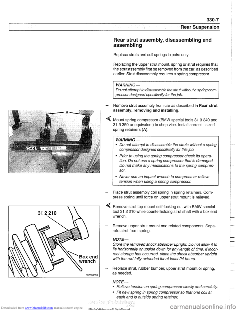
4 Mount spring compressor (BMW special tools 31 3 340 and
31 3 350 or equivalent) in shop vice. Install correct-sized
spring retainers
(A).
WARNING-
Do not attempt to disassemble the struts without a spring
compressor designed specifically for this job.
* Prior to using the spring compressor checlc its opera-
tion. Do not use a spring compressor that is damaged.
Do not make any modifications to the spring compres-
sor.
Never use an impact wrench to compress or relieve
tension when using a spring compressor.
1
- Place strut assembly coil spring in spring retainers. Com-
press spring until force on upper strut mount is relieved.
Remove strut top mount self-locking nut with BMW special
tool
31 2 21 0 while counterholding strut shaft with a box end
wrench.
- Remove upper strut mount and related components. Sepa-
rate strut from spring.
NOTE-
Store the removed shock absorber upright Do not allow it to
lie horizontally or upside down for any length of time. If incor-
rect storage has occurred, place the
shoclc absorber upright
with the rod
fully extended for at least 24 hours.
- Replace strut, rubber bumper, upper strut mount or spring,
as needed.
NOTE- Relieve tension on spring compressor slowly and carefully.
Fit new spring in spring compressor so that one coil at
each end is outside spring retainer.
Page 715 of 1002
Downloaded from www.Manualslib.com manuals search engine
330-1 9
Rear suspension1
Swing arm ball joint, replacing
- Raise rear end of car and remove wheel.
Make sure the car is firmly supported on jack stands de-
signed for the purpose. Place jack stands underneath struc-
tural chassis points. Do not place jack stands under
suspension
parts.
- Sport Wagon model: Support wheel bearing carrier from be-
low.
CA
UTION-
The shock absorberprevents the drive axle and wheel bear-
ing carrier from dropping too far. Supporting the wheel bear-
ing carrier before disconnecting the
shoclc absorber
mounting fastenerprevents damage to the brake hose, park-
ing
brake cable and drive axle CVjoints.
- Model with air shock absorbers: Detach air supply line from
shoclc absorber. Plug ports and lines to keep out dirt.
- Sport Wagon model: Remove shock absorber lower mount-
ing bolt.
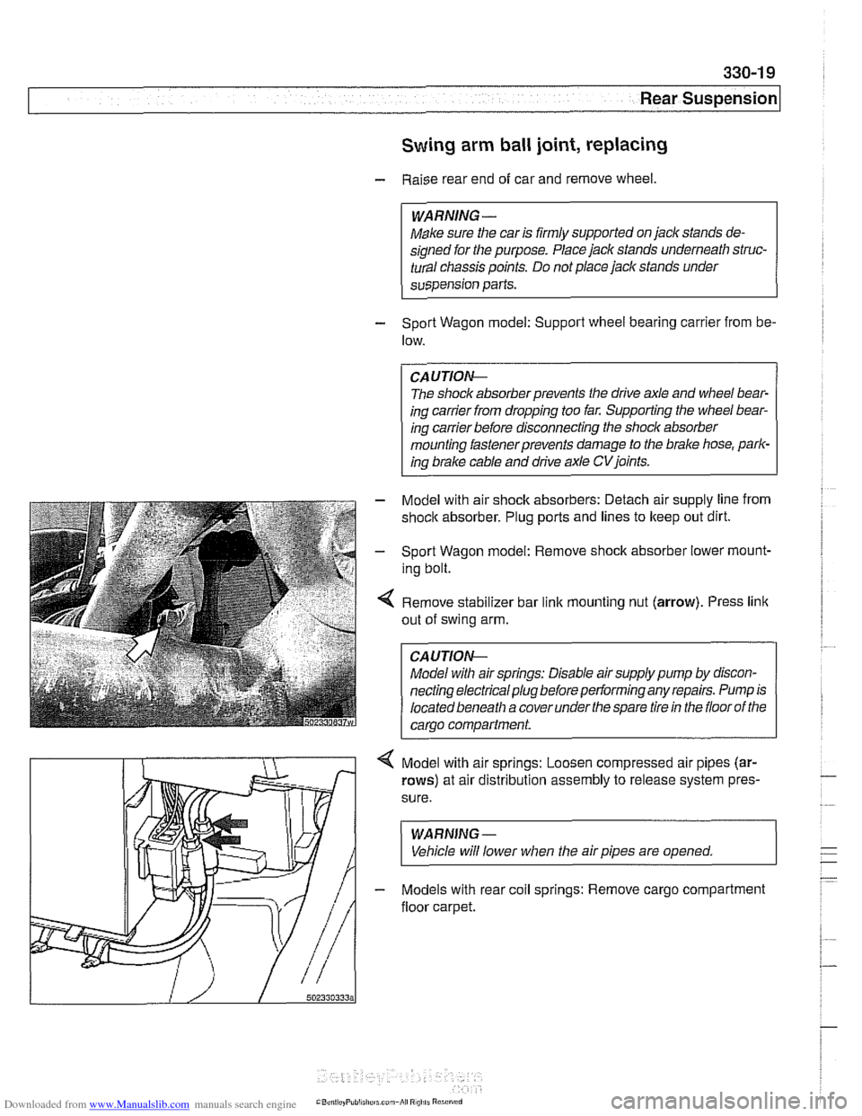
4 Remove stabilizer bar link mounting nut (arrow). Press link
out of swing arm.
Model with air springs: Disable air supply pump by discon-
necting electrical plug before performing any repairs. Pump is
located beneath a cover under
the spare tire in the floor of the
carao
comoartment.
4 Model with air springs: Loosen compressed air pipes (ar-
rows) at air distribution assembly to release system pres.
sure.
WARNING-
Vehicle will lower when the air pipes are opened.
- Models with rear coil springs: Remove cargo compartment
floor carpet.
Page 735 of 1002
Downloaded from www.Manualslib.com manuals search engine
330-39
I Rear suspension1
- Remainder of installation is reverse of removal, noting the fol-
lowing.
Models with coil springs: Fit spring correctly in lower spring
seat.
* Models with air suspension: Fit eccentric lug at bottom of
air spring in recess of wheel carrier spring seat.
Always use new self-locking nuts.
- Make sure all threaded bolts, nuts and mating surfaces are
clean.
a Tighten fasteners to final torque only after vehicle has
been lowered and suspension has settled.
Stake axle collar nut afler tightening.
Tightening torques
ABS pulse sensor to wheel bearing 8 Nm (6
ft-lb)
carrier
Air spring to wheel bearing carrier 20 Nm (15 ft-lb)
Brake rotor to hub 16 Nm (12
it-lb)
Rear axle shaft to hub (M27) 300 Nm (221 ft-lb)
Rear brake pad carrier (caliper) to wheel 65 Nm (48 ft-lb)
bearing carrier
Road wheel to hub
120ilONm
(89 k7 ft-lb)
Swing arm to wheel bearing carrier 256 Nm (189 it-lb)
Upperfrontcontrol arm (traction strut) to 65 Nm (48 ft-lb)
wheel carrier
Upper rear control arm to wheel carrier 142 Nm (105 ft-lb)
Rear wheel bearing, replacing
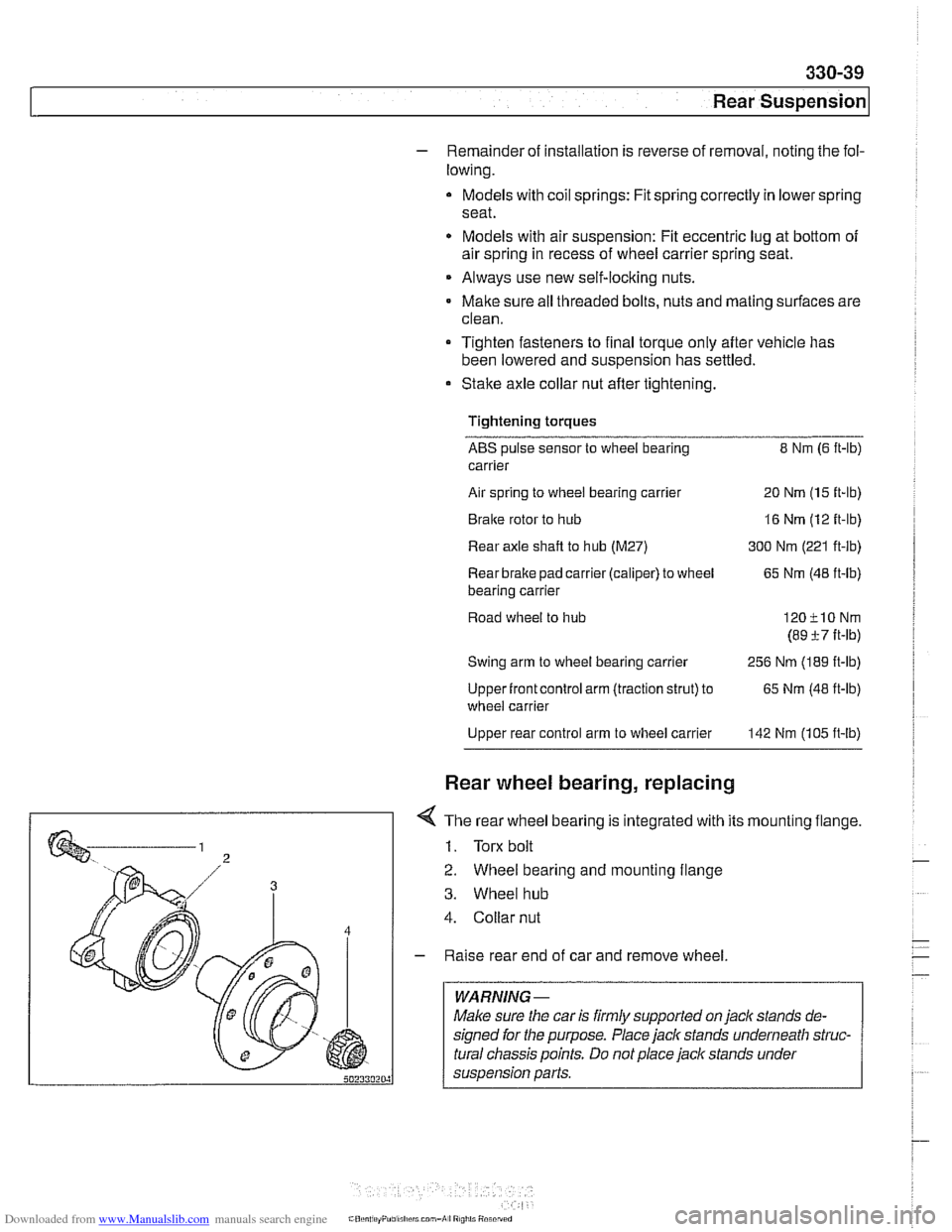
< The rear wheel bearing is integrated with its mounting flange.
1. Torx bolt
2. Wheel bearing and mounting flange
3. Wheel hub
4. Collar nut
- Raise rear end of car and remove wheel.
WARNING -
Make sure the car is firmly supported on jaclc stands de-
signed for the purpose. Place jack stands underneath struc-
tural chassis points. Do not place jack stands under
suspension parts.
Page 745 of 1002
Downloaded from www.Manualslib.com manuals search engine
33UFinal Drive
General ........................... ,331 -2 Drive Axles ....................... 331 -1 4
Special tools
........................ ,331 -2 Drive axle assembly ................. 331-14
Aluminum suspension components
...... ,331-4 Drive axle, removing and
installing (sedan)
.................... 331-14 ........................ Final Drive ,331 -5
Drive axle, removing
........... ...... Final drive, removing and installing ,331-5 and (Sport Wagon) 331-15
...................... Differential oil level, checking ........... ,331-6 CV joint boots 331-17 Final drive in~ut shaft seal, replacing ..... ,331-7 .
Final drive oitput shaft seals, replacing . . ,331-10
Final drive cover, removing and installing ,331-12
Final drive mounts, replacing .......... ,331-12
Page 751 of 1002
Downloaded from www.Manualslib.com manuals search engine
Final Drive
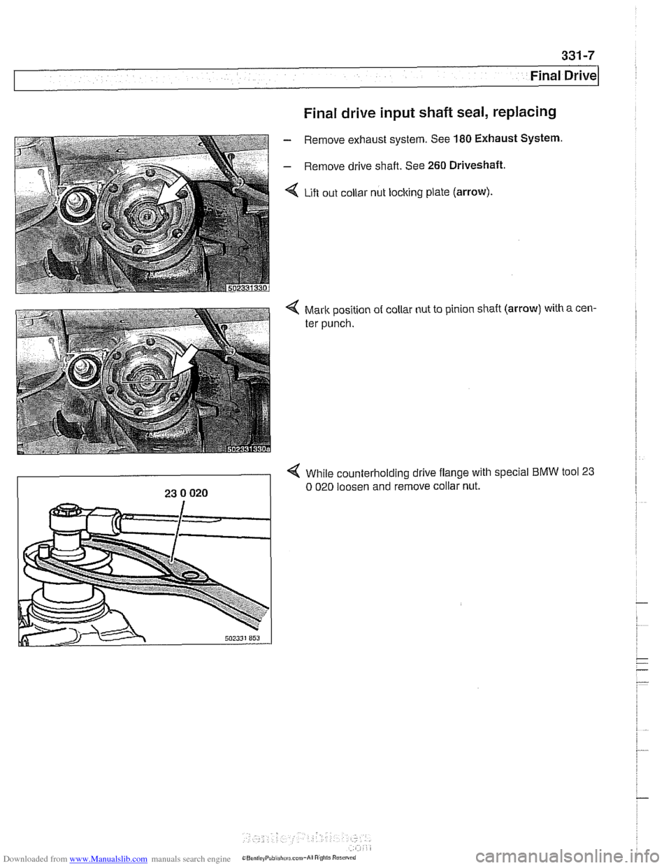
Final drive input shaft seal, replacing
- Remove exhaust system. See 180 Exhaust System
- Remove drive shaft. See 260 Driveshaft.
< Lift out collar nut locking plate (arrow).
4 While counterholding drive flange with special BMW tool 23
23 0 020 0 020 loosen and remove collar nut.