Wir BMW 540i 1997 E39 Workshop Manual
[x] Cancel search | Manufacturer: BMW, Model Year: 1997, Model line: 540i, Model: BMW 540i 1997 E39Pages: 1002
Page 889 of 1002
Downloaded from www.Manualslib.com manuals search engine
Interior ~riml
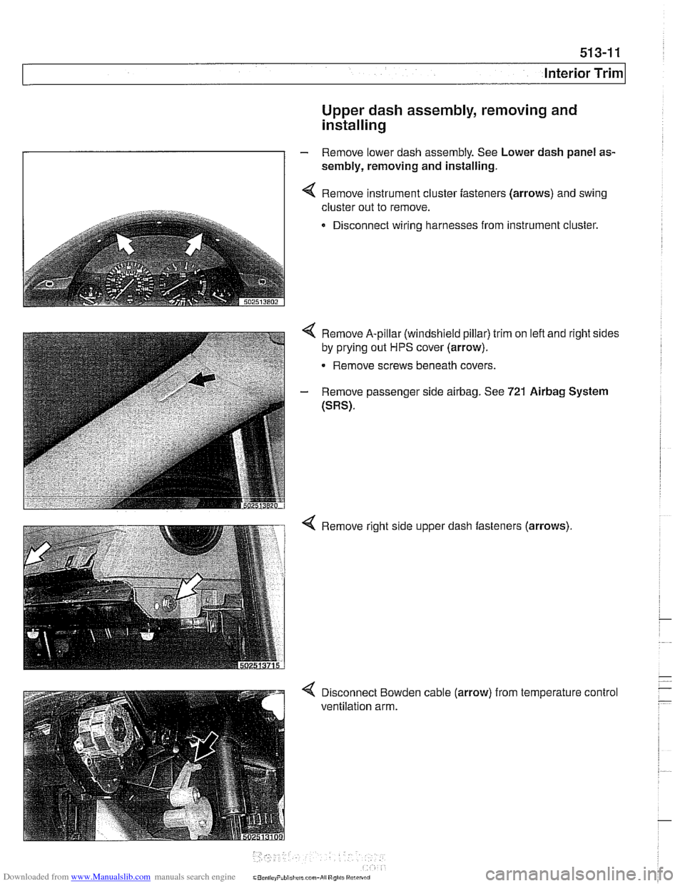
Upper dash assembly, removing and
installing
- Remove lower dash assembly. See Lower dash panel as-
sembly, removing and installing.
I I 4 Remove instrument cluster fasteners (arrows) and swing
cluster out to remove.
Disconnect wiring harnesses from instrument cluster.
4 Remove A-pillar (windshield pillar) trim on left and right sides
by prying out
HPS cover (arrow).
- Remove screws beneath covers.
- Remove passenger side airbag. See 721 Airbag System
(SRS).
Page 892 of 1002
Downloaded from www.Manualslib.com manuals search engine
51 3-1 4
llnterior Trim
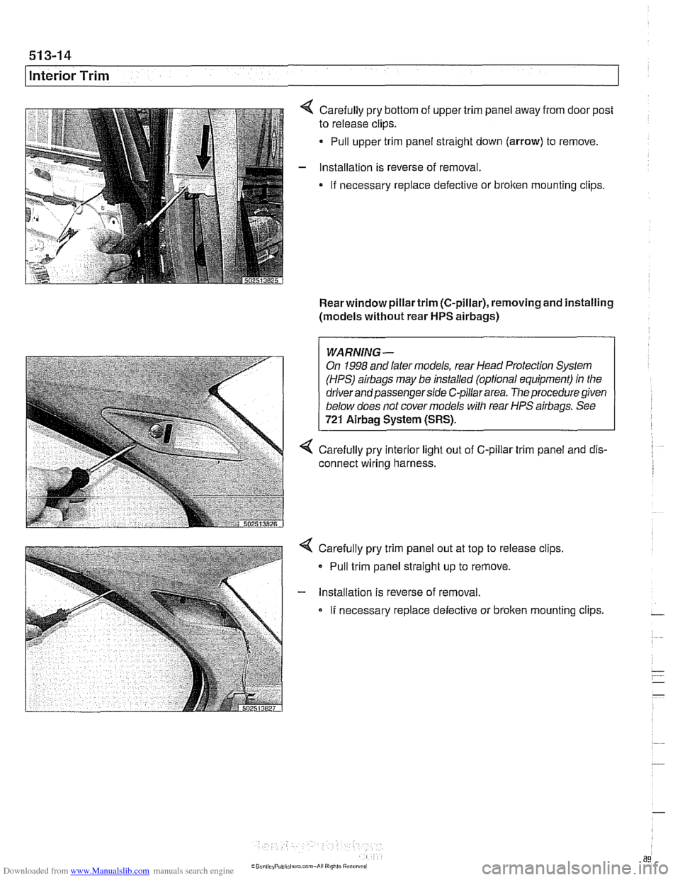
Carefully pry bottom of upper trim panel away from door post
to release clips.
Pull upper trim panel straight down (arrow) to remove.
Installation is reverse of removal.
If necessary replace defective or
broken mounting clips.
Rear window pillartrim (C-pillar), removing and installing
(models without rear
HPS airbags)
1 I
WARNING-
On 1998 and later models, rear Head Protection System
(HPS)
airbags may be installed (optional equipment) in the
driver and passenger side C-pillar area.
The procedure given
below does not cover models with rear HPS airbags. See
721 Airbag System (SRS).
4 Carefully pry interior light out of C-pillar trim panel and dis-
connect wiring harness.
Carefully pry trim panel out at top to release clips,
- Pull trim panel straight up to remove.
- lnstallation is reverse of removal.
If necessary replace defective or broken mounting clips.
Page 893 of 1002
Downloaded from www.Manualslib.com manuals search engine
51 3-1 5
I Interior Trim
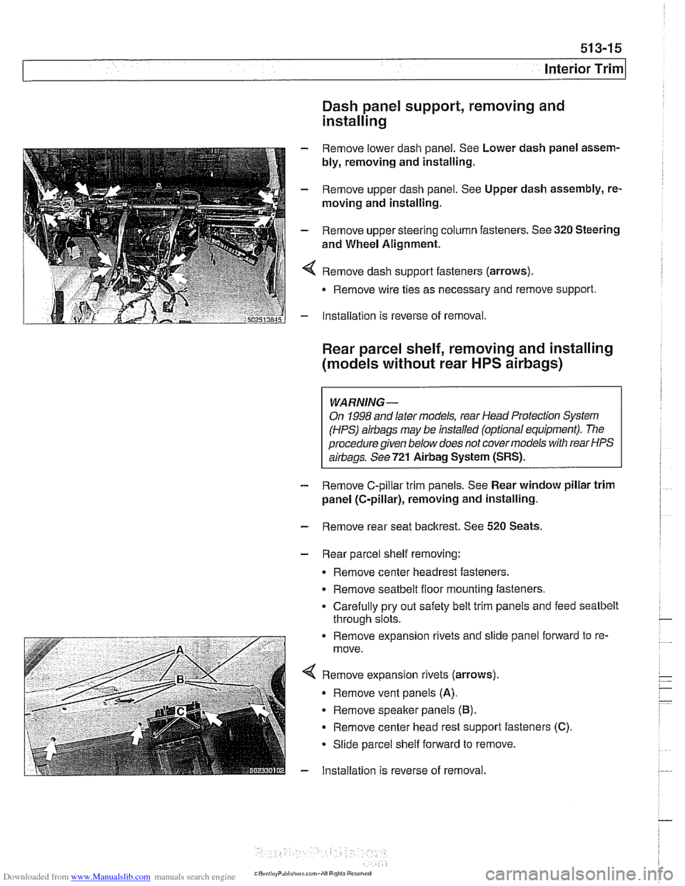
Dash panel support, removing and
installing
- Remove lower dash panel. See Lower dash panel assem-
bly, removing and installing.
- Remove upper dash panel. See Upper dash assembly, re-
moving and installing.
- Remove upper steering column fasteners. See 320 Steering
and Wheel Alignment.
4 Remove dash support fasteners (arrows).
Remove wire ties as necessary and remove support.
- Installation is reverse of removal.
Rear parcel shelf, removing and installing
(models without rear
HPS airbags)
WARNING-
On 1998 and later models, rear Head Protection System
(HPS)
airbags may be installed (optional equipment). The
procedure given below does not covermodels with rear HPS
airbags. See721
Airbag System (SRS).
- Remove C-pillar trim panels. See Rear window pillar trim
panel (C-pillar), removing and installing.
- Remove rear seat backrest. See 520 Seats.
- Rear parcel shelf removing:
Remove center headrest fasteners.
Remove
seatbelt floor mounting fasteners.
Carefully pry out safety belt trim panels and feed
seatbelt
through slots.
. . . - -. . . . . . . . . Remove expansion rivets and slide pane fonvard to re-
move.
< Remove expanson r:vets (arrows).
Remove vent panels (A).
Remove speafter pane s (B).
Remove center head rest s-pporl fasteners (C).
Slioe parcel shelf forward lo remove.
- lnsta lation s reverse of removal.
Page 896 of 1002
Downloaded from www.Manualslib.com manuals search engine
51 5-2
/Central Locking and Anti-Theft
This section covers repair information for door, trunk and car-
go compartment locks, central locking, electronic
immob~liza-
tion (EWS) and anti-theft alarm (DWA).
€39 cars are equipped with sophisticated self-diagnostic elec-
trical systems. When experiencing malfunctions relating to
central locking. EWS or anti-theft systems, start the diagnosis
process using the
BMW service tester DIS, GT 1, MoDiC or
equivalent scan tool. An advanced diagnostic scan tool can
usually pinpoint electrical faults quickly and safely.
Additional electrical information can be found in:
610 Electrical Component Locations
ELE Electrical Wiring Diagrams
Central locking in E39 vehicles controls the door
locks, trunk
or tailgate lock and fuel filler flap lock. The control module for
the Central Body Electronics system (ZKE
Ill), lknown as the
General Module (GM
Ill), controls central locking.
ZKE
Ill manages the following central locking related func-
tions:
Central locking
* Keyless entry
Key memory
Power trunk release
Electric opening of tailgate
DWA alarm system
Diagnosis
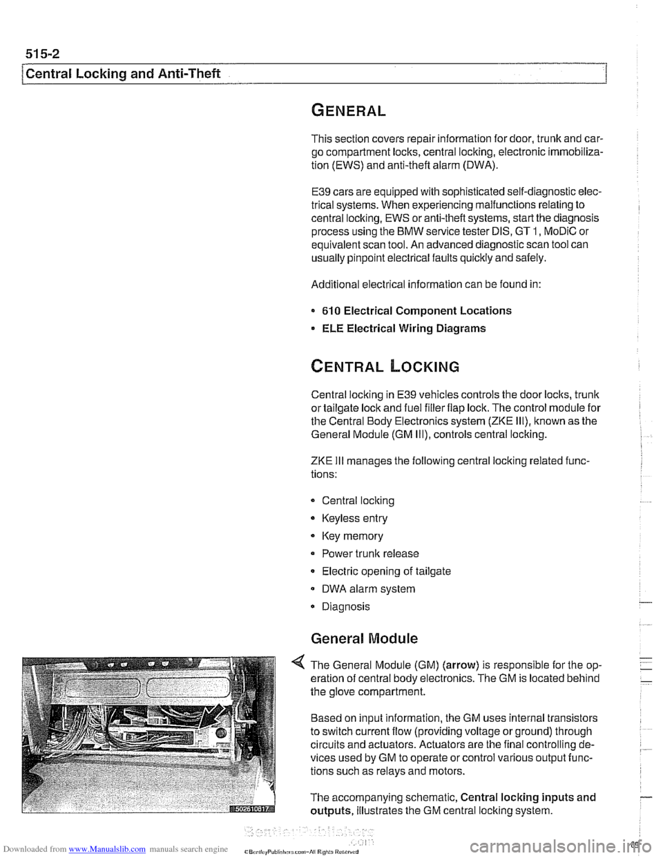
General Module
4 The General Module (GM) (arrow) is responsible for the op-
eration of central body electronics. The GM is located behind
the glove compartment.
Based on input information, the GM uses internal transistors
to switch current flow (providing voltage or ground) through
circuits and actuators. Actuators are the final controlling de-
vices used by GM to operate or control various output func-
tions such as relays and motors.
The accompanying schematic, Central locking inputs and
outputs, illustrates the GM central locking system.
Page 914 of 1002
Downloaded from www.Manualslib.com manuals search engine
515-20
Central Locking and Anti-Theft
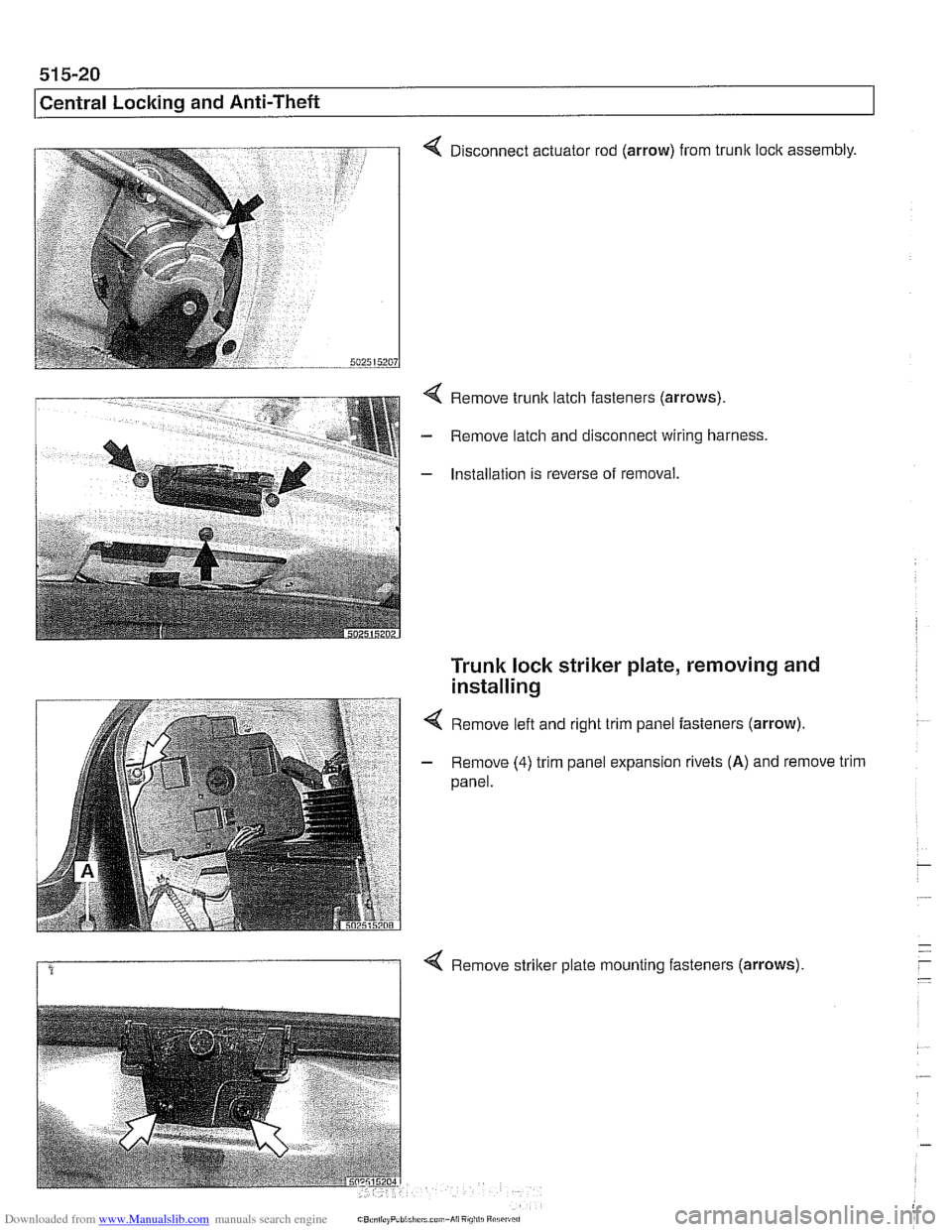
4 Disconnect actuator rod (arrow) from trunk loclc assembly.
4 Remove trunk latch fasteners (arrows).
- Remove latch and disconnect wiring harness.
- Installation is reverse of removal.
Trunk lock striker plate, removing and
installing
4 Remove left and right trim panel fasteners (arrow).
- Remove (4) trim panel expansion rivets (A) and remove trim
panel.
1 4 Remove striker plate mounting fasteners (arrows).
Page 917 of 1002
Downloaded from www.Manualslib.com manuals search engine
Central Lockina and ~nti- heft
EWS control module, replacing
NOTE-
EWS control module location varies depending on version of
EWS installed.
Checlc the table €39 EWS applications.
- Disconnect battery negative (-) cable.
CA UTIOI\C
Prior to disconnecting the battery, read the battery discon-
nection cautions given in
001 General Warnings and Cau-
tions.
- EWS II: Control module is accessible from behind glove com-
partment.
Remove trim below glove compartment.
Lower relay and module holder to access EWS control
module
EWS
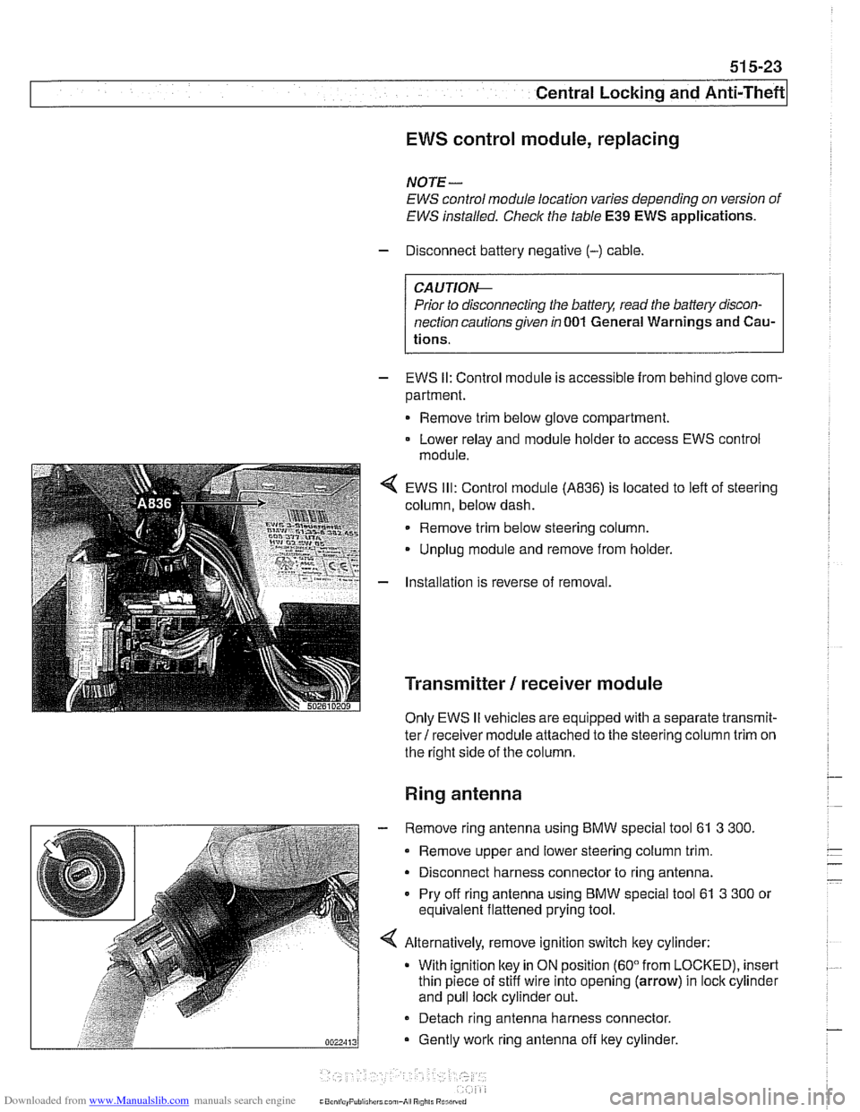
Ill: Control module (A836) is located to left of steering
column, below dash.
Remove trim below steering column.
Unplug module and remove from holder.
Installation is reverse of removal.
Transmitter / receiver module
Only EWS II vehicles are equipped with a separate transmit-
ter! receiver module attached to the steering column trim on
the right side of the column.
Ring antenna
- Remove ring antenna using BMW special tool 61 3 300.
Remove upper and lower steering column trim.
Disconnect harness connector to ring antenna.
Pry off ring antenna using
BMW special tool 61 3 300 or
equivalent flattened prying tool.
Alternatively, remove ignition switch key cylinder: With ignition
ltey in ON position (60" from LOCKED), insert
thin piece of stiff wire into opening (arrow) in lock cylinder
and pull lock cylinder out.
- Detach ring antenna harness connector.
Gently
work ring antenna off ltey cylinder.
CaonliayPuliiliirrl can,-A, R0,il. Rurilrrrri
Page 927 of 1002
Downloaded from www.Manualslib.com manuals search engine
Seats
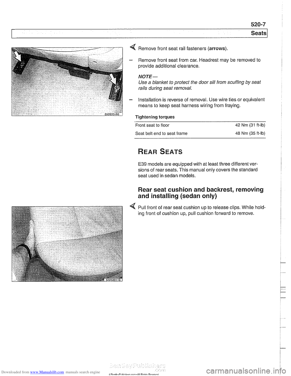
< Remove front seat rail fasteners (arrows)
- Remove front seat from car. Headrest may be removed to
provide additional clearance.
NOTE-
Use a blanket to protect the door sill from scuffing by seat
rails
during seat removal.
- Installation is reverse of removal. Use wire ties or equivalent
means to keep seat harness wiring from fraying.
Tightening torques
Front seat to floor
42 Nm (31 ft-lb)
Seat belt end to seat frame
48 Nm (35 ft-lb)
E39 models are equipped with at least three different ver-
sions of rear seats. This manual only covers the standard
seat used in sedan models.
Rear seat cushion and backrest, removing
and installing (sedan only)
4 Pull front of rear seat cushion up to release clips. While hold-
ing front of cushion up, pull cushion forward to remove.
Page 943 of 1002
Downloaded from www.Manualslib.com manuals search engine
Seat ~eltsl
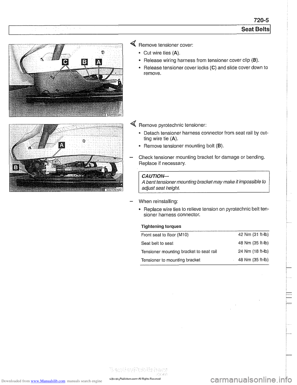
< Remove tensioner cover:
Cut wire ties (A).
Release wiring harness from tensioner cover clip (B).
- Release tensioner cover locks (C) and slide cover down to
remove.
- When reinstalling:
Replace wire ties to relieve tension on pyrotechnic belt
ten-
sioner harness connector.
Tightening torques . -
Front seat to floor (M10) 42 Nm (31 it-lb)
Seat belt to seat 48 Nm (35 It-lb)
Tensioner mounting bracitet
to seat rail 24 Nm (18 it-lb)
Tensioner to mounting bracket 48 Nm (35 it-lb)
Page 951 of 1002
Downloaded from www.Manualslib.com manuals search engine
721 -3
Airbag System (SRS)
MRS Ill adds the following features:
MRS
Ill employs "smart" technology. Smart technology re-
fers to the control module's programming for the deploy-
ment of the airbags, in stages depending on the severity of
the impact.
Two-stage a~rbag for ooln drver and passenger Alloivs for
a softer
c~snioning elfecl when the airbags are lr ggered at
lighter impact,
MRS
Ill satellite sensors use 2 wire connectors
Rear side
airbags arrive de-activated from the factory and
can only be activated upon written request from the cus-
tomer.
Rear seat head protection is available when ordered with
optional rear seat side airbags.
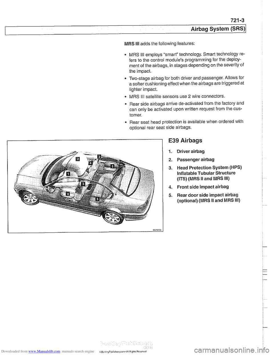
E39 Airbags
Driver airbag
Passenger airbag
Head Protection System (HPS)
Inflatable Tubular Structure
(ITS) (MRS
II and MRS Ill)
Front side impact airbag
Rear door side impact airbag
(optional) (MRS I1 and MRS Ill)
Page 958 of 1002
Downloaded from www.Manualslib.com manuals search engine
721 -1 0
/Airbag System (SRS)
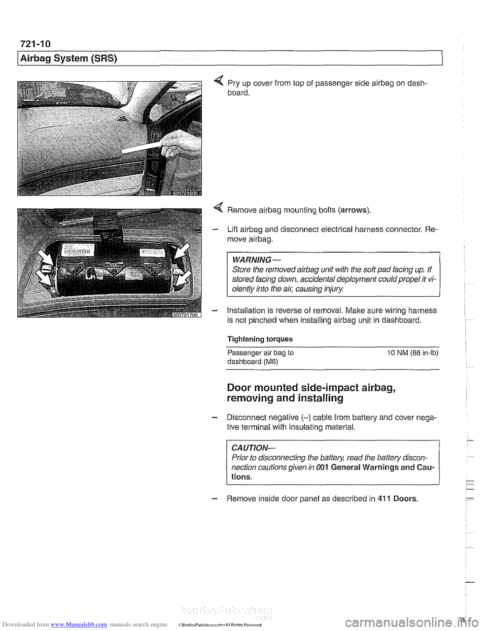
4 Pry up cover from top of passenger side airbag on dash-
board.
4 Remove airbag mounting bolts (arrows)
- Lift airbag and disconnect electrical harness connector. Re-
move
airbag.
WARNING-
Store the removed airbag unit with the soft pad facing up. If
stored facing down, accidental deployment could propel it vi-
olentlv into the
ail: causino inium
- Installation is reverse of removal. Make sure wiring harness
is not pinched when installing
airbag unit in dashboard.
Tightening torques
-
Passenger alr bag to 10 NM (88 in-lb)
dashboard (Me)
Door mounted side-impact airbag,
removing and installing
- Disconnect negatlve (-) cable from battery and cover nega-
tive terminal with insulating material.
CAUTION-
Prior to disconnecting the battea read the battery discon-
nection cautions given
in 001 General Warnings and Cau-
tions.
- Remove inside door panel as described in 41 1 Doors