Wir BMW 540i 1997 E39 Workshop Manual
[x] Cancel search | Manufacturer: BMW, Model Year: 1997, Model line: 540i, Model: BMW 540i 1997 E39Pages: 1002
Page 839 of 1002
Downloaded from www.Manualslib.com manuals search engine
Trunk Lid, Tailgate
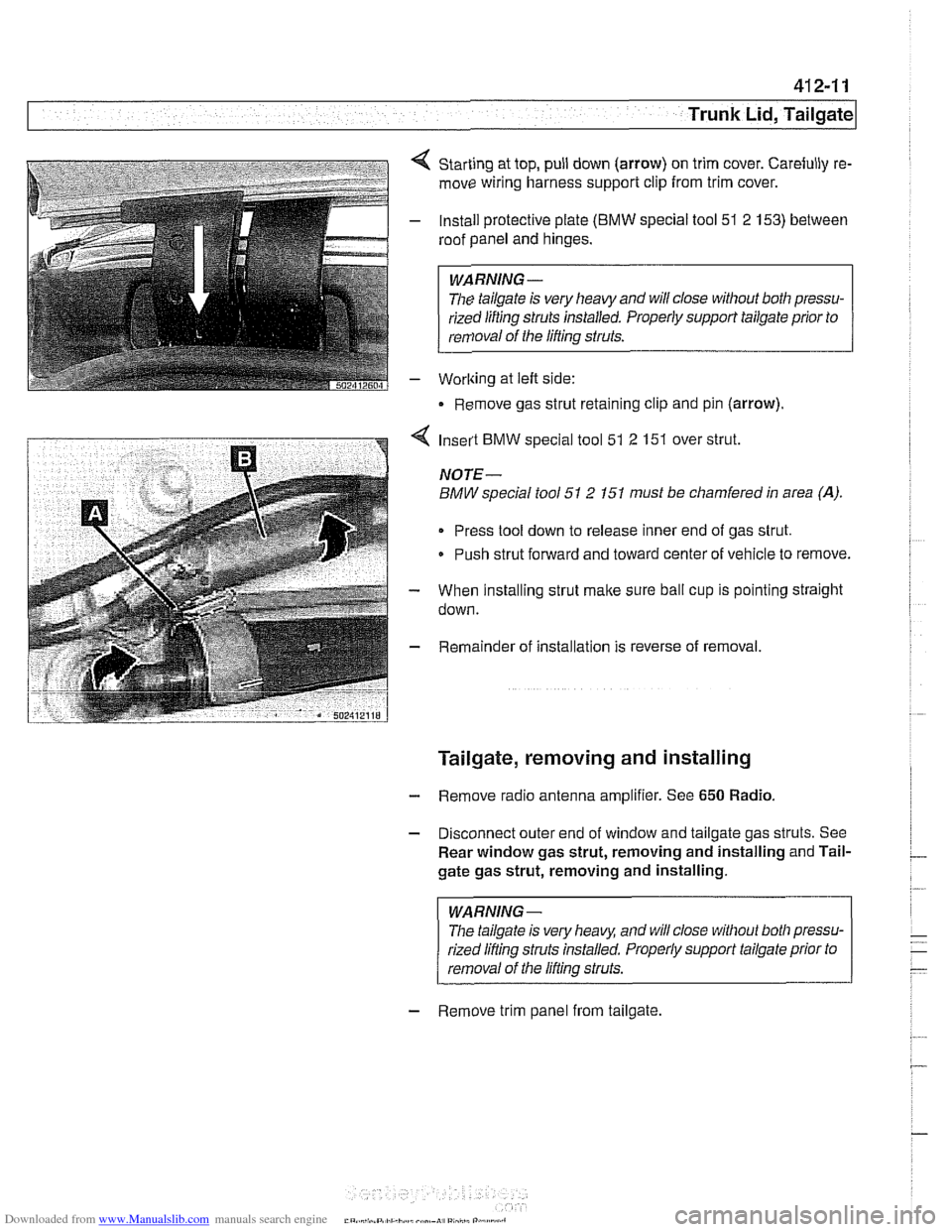
Starting at top, pull down (arrow) on trim cover. Carefully re-
move wiring harness support clip from trim cover.
Install protective plate
(BMW special tool 51 2 153) between
roof panel and hinges.
WARNING -
The tailgate is very heavy and will close without both pressu-
rized lifting
struts installed. Properly support tailgate prior to
removal of the lifting struts.
Worlting at left side:
Remove gas strut retaining clip and pin (arrow).
4 Insert BMW special tool 51 2 151 over strut.
NOTE-
BMW special tool 51 2 151 must be chamfered in area (A).
Press tool down to release inner end of gas strut.
Push strut forward and toward center of vehicle to remove.
- When installing strut make sure ball cup is pointing straight
down.
- Remainder of installation is reverse of removal.
Tailgate, removing and installing
- Remove radio antenna amplifier. See 650 Radio.
- Disconnect outer end of window and tailgate gas struts. See
Rear window gas strut, removing and installing and Tail-
gate gas strut, removing and installing.
WARNING-
The tailgate is very heaq and will close without both pressu-
rized lifling struts installed. Properly support tailgate prior to
removal of the lifling struts.
- Remove trim panel from tailgate.
Page 857 of 1002
Downloaded from www.Manualslib.com manuals search engine
Exterior Trim. ~um~ers/
Front bumper, removing and installing
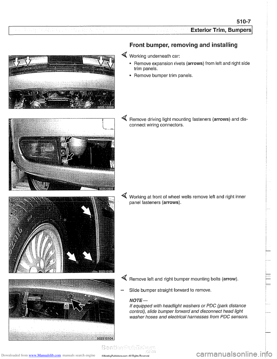
< Working underneath car:
Remove expansion rivets
(arrows) from lefl and right side
trim panels.
Remove bumper trim panels.
4 Remove driving light mounting fasteners (arrows) and dis-
connect wiring connectors.
4 Worlting at front of wheel wells
panel fasteners
(arrows).
remove left and right inner
Page 867 of 1002
Downloaded from www.Manualslib.com manuals search engine
51 2-3
Door Windows
Window switches
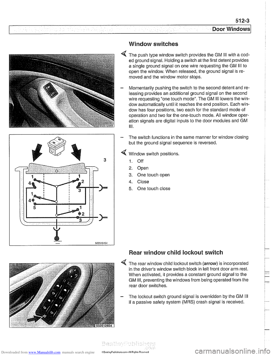
4 The push type window switch provides the GM Ill with a cod-
ed ground signal. Holding a switch at the first detent provides
a single ground signal on one wire requesting the GM
Ill to
open the window. When released, the ground signal is re-
moved and the window motor stops.
- Momentarily pushing the switch to the second detent and re-
leasing provides an additional ground signal on the second
wire requesting "one touch mode". The GM
Ill lowers the win-
dow automatically until it reaches the end position. Each win-
dow has four positions, two each for the standard mode of
operation and two for the one-touch mode. All window oper-
ation signals are digital inputs to the door modules and GM
111.
- The switch functions in the same manner for window closing
but the ground signal sequence is reversed.
4 Window switch positions.
1. Off
2. Open
3. One touch open
4. Close
5. One touch close
Rear window child lockout switch
4 The rear window child lockout switch (arrow) is incorporated
in the driver's window switch block in
leit front door arm rest.
When activated, it provides a constant ground signal to the
GM
Ill, preventing the windows from being operated from the
rear door switches.
- The lockout switch ground signal is overridden by the GM Ill
if a passive safety system (MRS) crash signal is received.
Page 868 of 1002
Downloaded from www.Manualslib.com manuals search engine
51 2-4
I Door Windows
/ Anti-trap strip
Power window motors
The window motors are mounted on cable regulators. The
window motor control circuit consists of two wires for operat-
ing the motor in both directions.
The motors are activated by relays in the GM
Ill. The relays
provide either power or ground depending on the direction of
window travel. The GM
Ill controls the polarity based on a re-
quest to run the window from a window switch or a conve-
nience
openinglclosing signal.
Convenience openinglclosing
The GM Iii provides the convenience openlclose feature, pro-
viding control of the power windows (and sunroof) from out-
side the vehicle with the key in the driver's door lock. The FZV
(remote key) provides the same function for window opening
only.
Anti-trap protection is active during convenience closing from
the driver's door lock.
If the GM receives a request to operate convenience closing
or opening for more than
110 seconds, the function is deacti-
vated and a
fault code is stored.
Window anti-trap protection
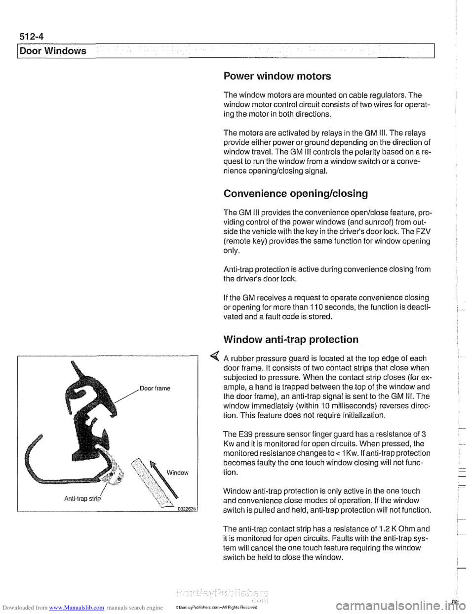
4 A rubber pressure guard is located at the top edge of each
door frame. It consists of two contact strips that close when
subjected to pressure. When the contact strip closes (for ex-
ample, a hand is trapped between the top of the window and
the door frame), an anti-trap signal is sent to the GM
Ill. The
window immediately (within
10 milliseconds) reverses direc-
tion. This feature does not require
initialization.
The E39 pressure sensor finger guard has a resistance of 3
Kw and it is monitored for open circuits. When pressed, the
monitored resistance changes to
< 1 Kw. if anti-trap protection
becomes faulty the one touch window closing will not func-
tion.
Window anti-trap protection is
only active in the one touch
and convenience close modes of operation. If the window
switch is pulled and held, anti-trap protection will not function.
The anti-trap contact strip has a resistance of
1.2 K Ohm and
it is monitored for open circuits. Faults with the anti-trap sys-
tem will cancel the one touch feature requiring the window
switch be held to close the window.
Page 870 of 1002
Downloaded from www.Manualslib.com manuals search engine
Door Windows
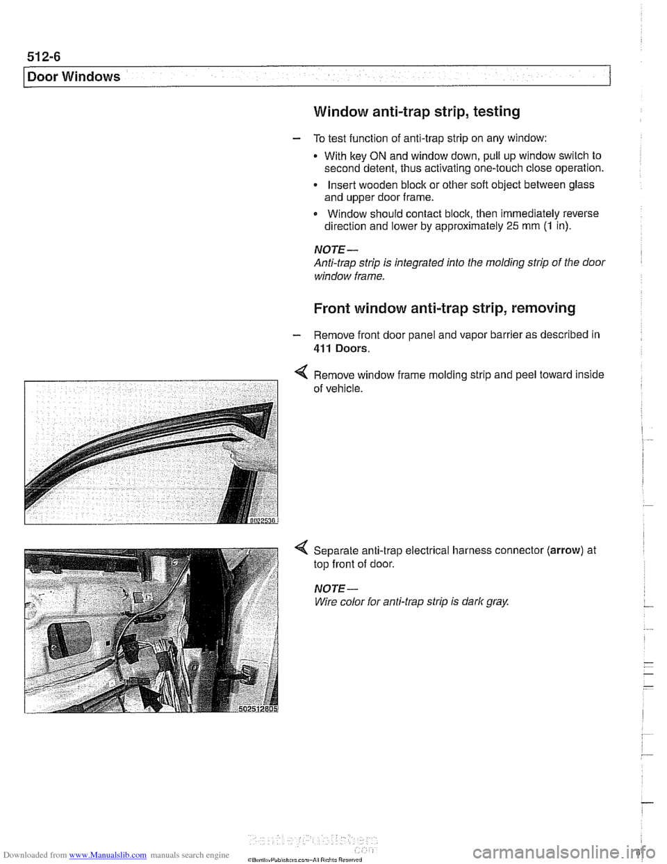
Window anti-trap strip, testing
- To test function of anti-trap strip on any window:
With key
ON and window down, pull up window switch to
second detent, thus activating one-touch close operation.
Insert wooden block or other soft object between glass
and upper door frame.
Window should contact block, then immediately reverse
direction and lower by approximately
25 mm (1 in).
NOTE-
Anti-trap strip is integrated into the molding strip of the door
window frame.
Front window anti-trap strip, removing
- Remove front door panel and vapor barrier as described in
411 Doors.
< Remove window frame mold~ng strlp and peel toward inside
7 of vehrcle.
Separate anti-trap electrical harness connector
top front of door.
NOTE-
Wire color for anti-trap strip is dark gray.
(arrow) at
Page 876 of 1002
Downloaded from www.Manualslib.com manuals search engine
512-12
I Door Windows
- Disconnect window from window guide rail as described in
Door window, removing
and installing. Do not remove
window from door.
* Push window up and use wedge to hold in position.
- If necessary, remove speaker unit from door.
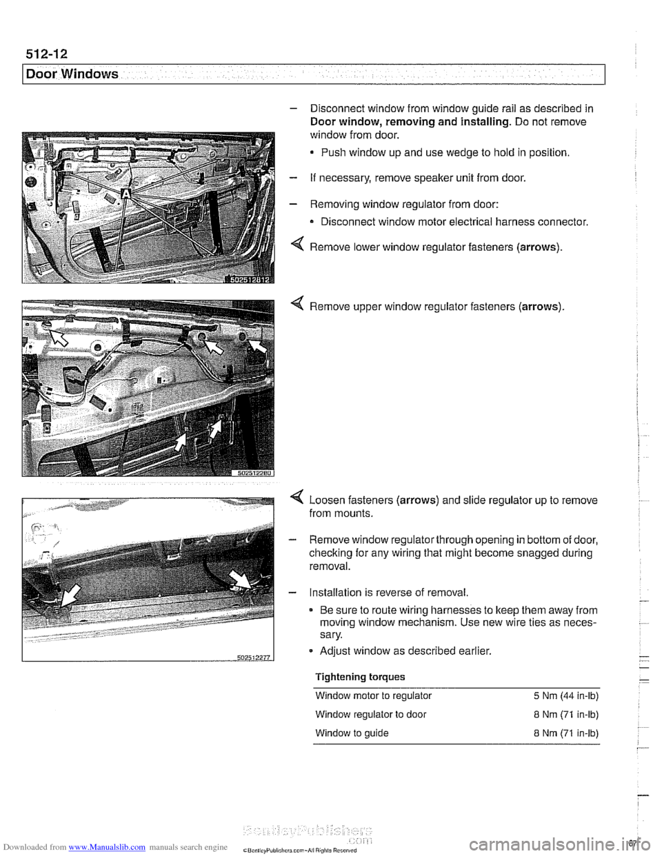
- Removing window regulator from door:
Disconnect window motor electrical harness connector.
4 Remove lower window regulator fasteners (arrows).
Remove window regulator fasteners (arrows)
Loosen fasteners (arrows) and slide regulator up to remove
from mounts.
- Remove window regulatorthrough opening in bottom of door,
checking for any wiring that might become snagged during
removal.
- Installation is reverse of removal.
Be sure to route wiring harnesses to keep them away from
moving window mechanism. Use new wire ties as neces-
sary.
-
Tightening torques -
Window motor to regulator 5 Nm (44 in-lb)
502512211
Window regulator to door 8 Nm (71 in-lb)
Adjust window
as described earlier.
- -
W~ndow to guide 8 Nm (71 in-lb)
--
Page 877 of 1002
Downloaded from www.Manualslib.com manuals search engine
Door windows1
Rear window regulator, removing and
installing
NOTE-
BMW recommends removing the window regulator and mo-
tor as one unit, then separating the
two on the bench.
- Disconnect negative (-) cable from battery
- Remove door panel as described in 411 Doors
- Remove airbag unit and vapor barrier from door. See 721
Airbag System (SRS).
- Disconnect window from window guide rail as described in
Door window, removing and installing. Do not remove
window from door.
Push window up and use wedge to
hold in position.
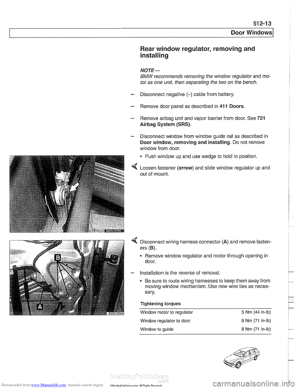
Loosen fastener (arrow) and slide window regulator up and
out of mount.
Disconnect wiring harness connector (A) and remove fasten-
ers
(6).
Remove window regulator and motor through opening in
door.
- Installation is the reverse of removal.
Be sure to route wiring harnesses to keep them away from
moving window mechanism. Use new wire ties as neces-
sary.
Tightening torques
Window motor to regulator
5 Nrn (44 in-ib)
Window regulator to door
Window to guide
8 Nrn (71 in-lb)
8 Nrn (71 in-lb)
Page 881 of 1002
Downloaded from www.Manualslib.com manuals search engine
513-3
Interior ~rirnl
The console between the two front seats starts behind the shifler housing. It houses the parking brake handle, optional
telephone and oddments storage tray. The rear portion of the
console houses the ashtray and covers the emergency brake
cable ends.
NOTE-
The accompanying photos illustrate a model with automatic
transmission. Manual transmission models are similar.
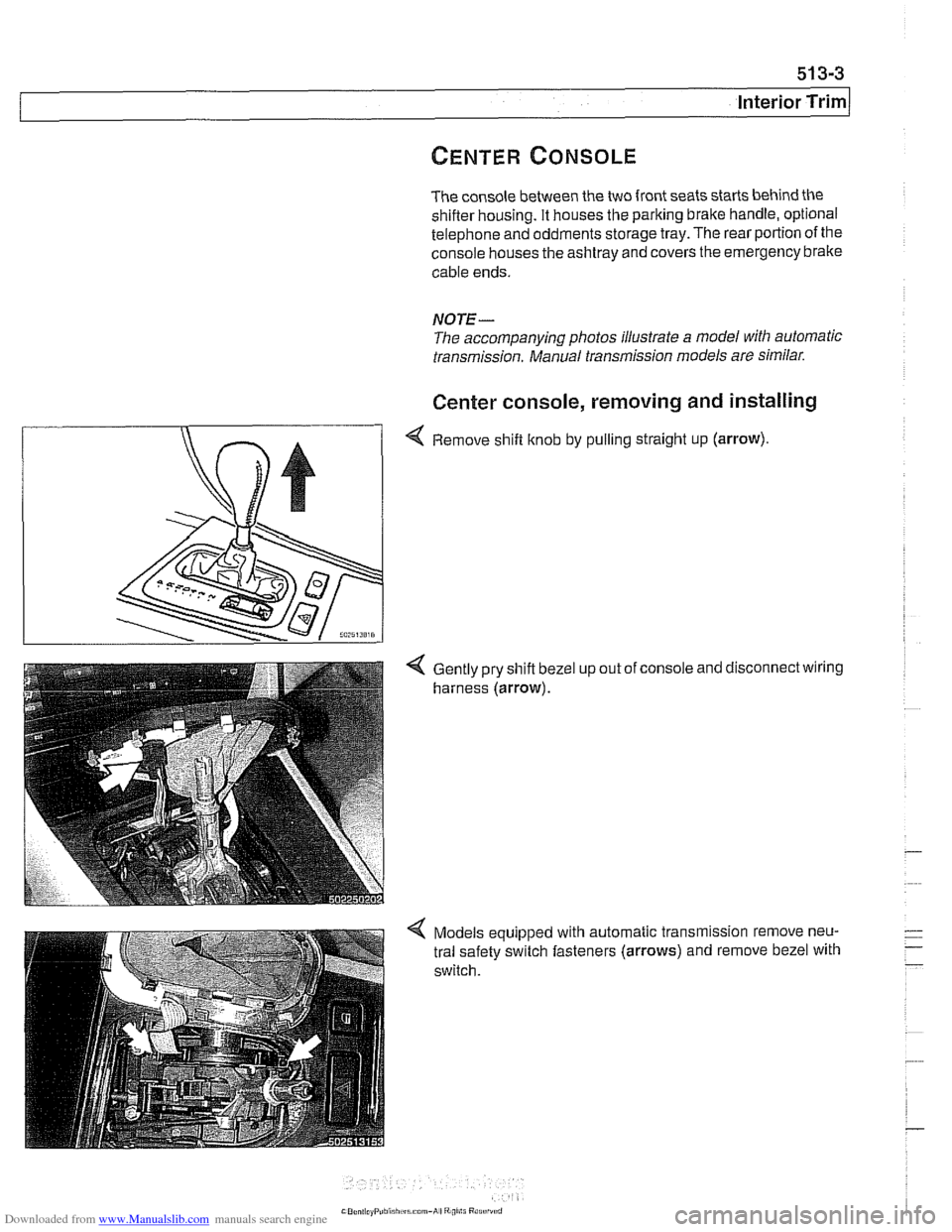
Center console, removing and installing
4 Remove shift knob by pulling straight up (arrow).
Gently pry shift bezel
harness (arrow). up
out of console and disconnect wiring
Models equipped with automatic transmission remove neu-
tral safety switch fasteners (arrows) and remove bezel with
switch.
Page 883 of 1002
Downloaded from www.Manualslib.com manuals search engine
Interior iriml
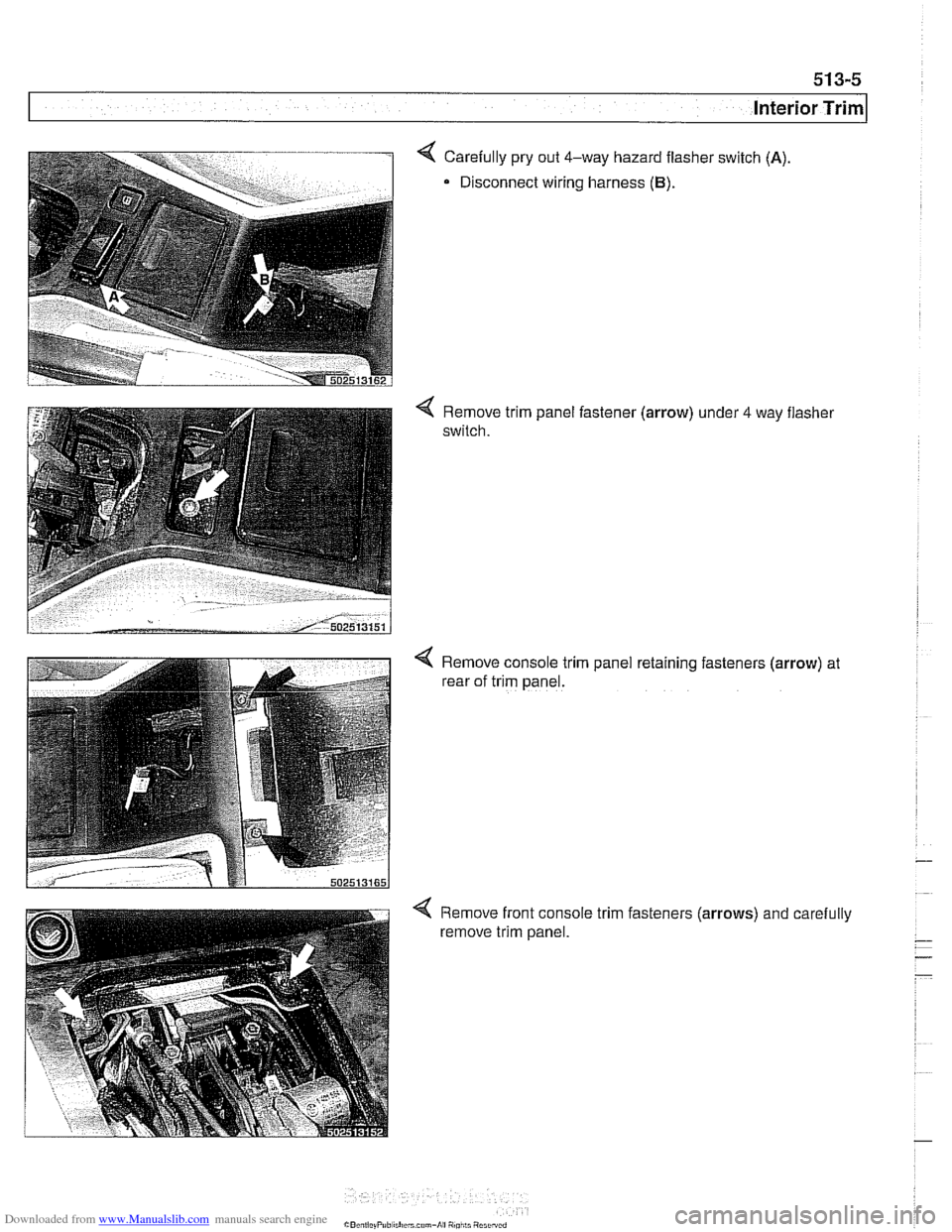
4 Carefully pry out 4-way hazard flasher switch (A)
Disconnect wiring harness (B).
Remove trim panel fastener (arrow) under 4 way flasher
switch.
4 Remove console trim panel retaining fasteners (arrow) at
rear of trim panel.
Remove front console trim fasteners
(arrows) and carefully
remove trim panel.
Page 886 of 1002
Downloaded from www.Manualslib.com manuals search engine
I Interior Trim
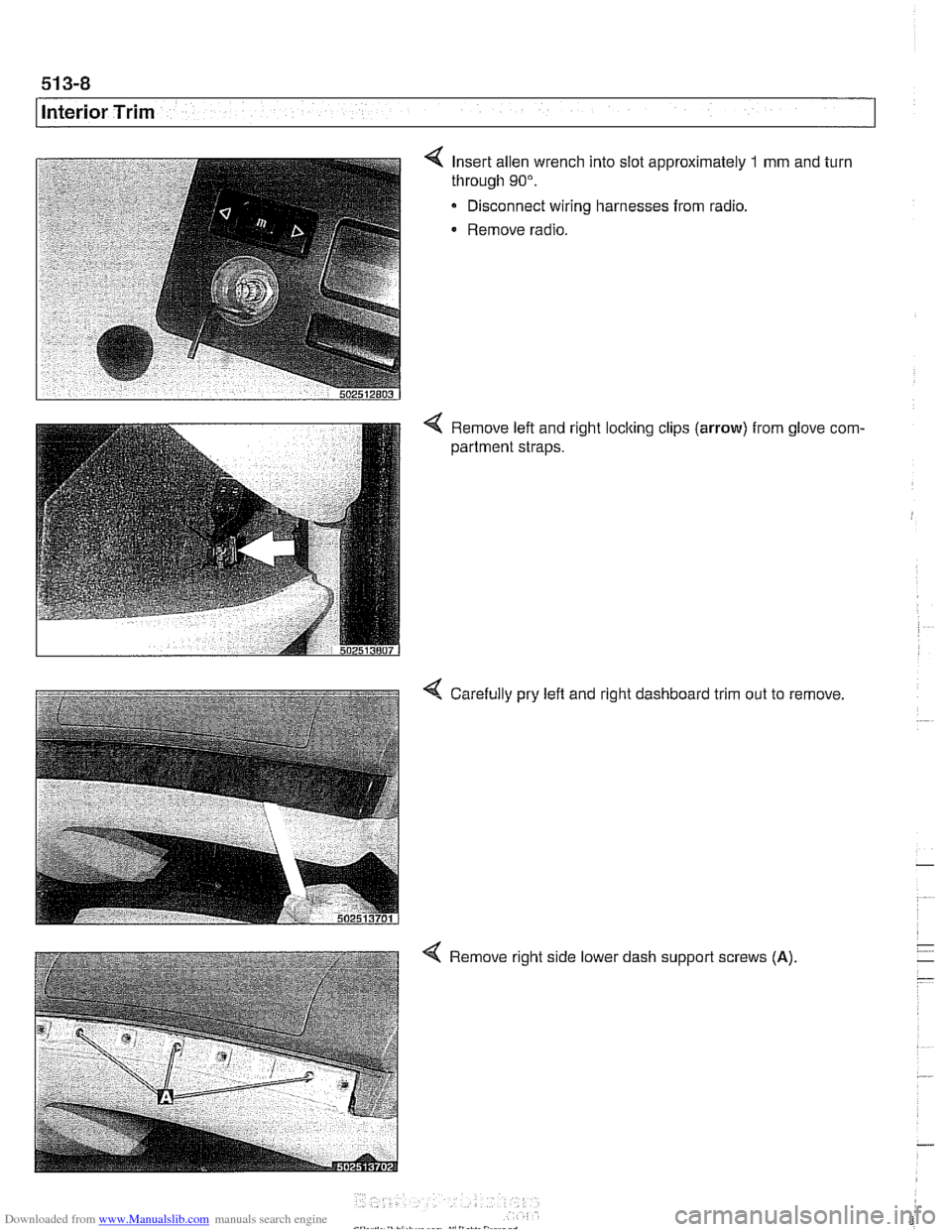
Insert allen wrench into slot approximately 1 mm and turn
through
90".
Disconnect wiring harnesses from radio.
Remove radio.
4 Remove left and right locking clips (arrow) from glove com-
partment straps.
4 Carefully pry left and right dashboard trim out to remove
4 Remove right side lower dash support screws (A)