Wir BMW 540i 1997 E39 Workshop Manual
[x] Cancel search | Manufacturer: BMW, Model Year: 1997, Model line: 540i, Model: BMW 540i 1997 E39Pages: 1002
Page 736 of 1002
Downloaded from www.Manualslib.com manuals search engine
330-40
Rear Suspension
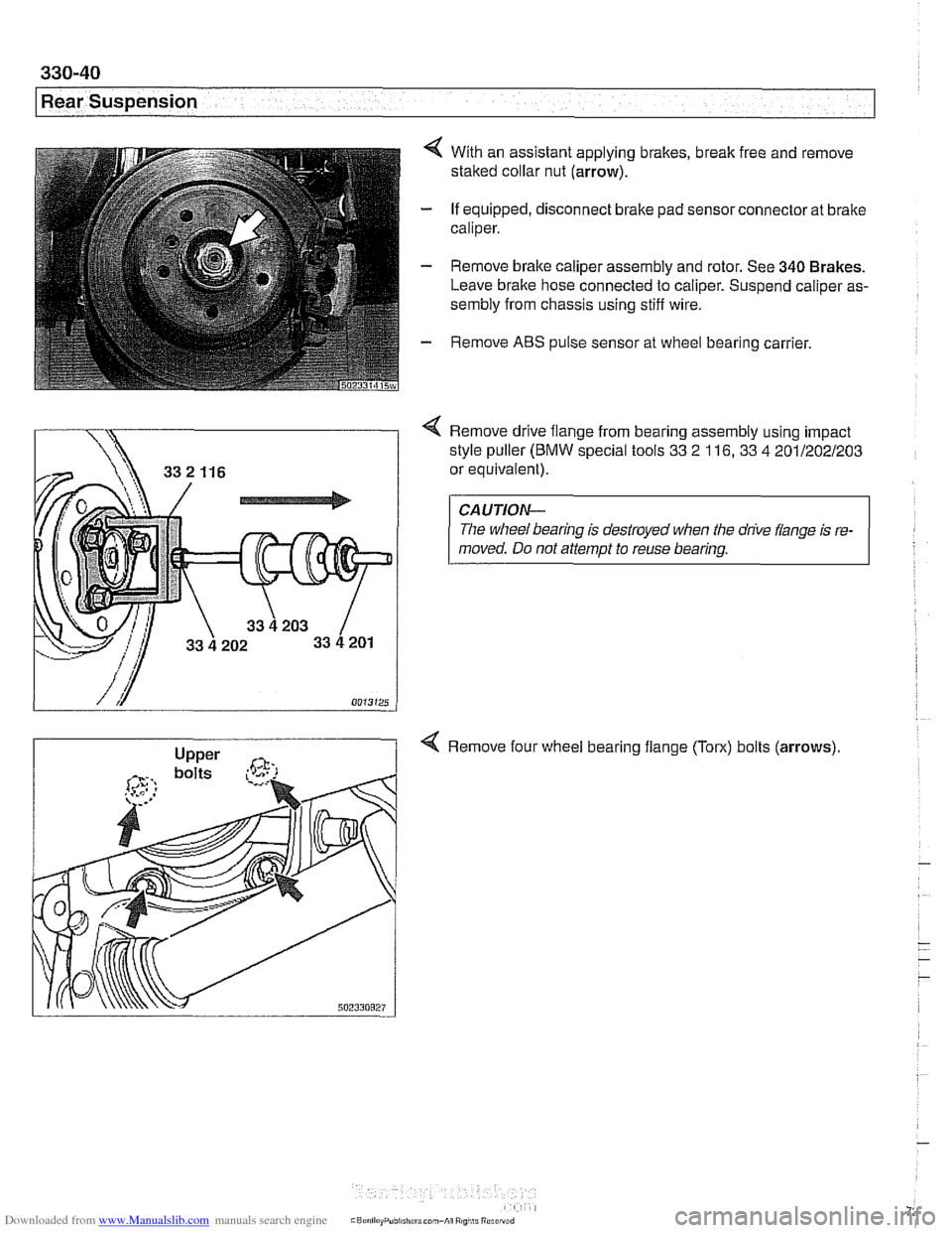
4 With an assistant applying brakes, break free and remove
staked collar nut (arrow).
- If equipped, disconnect brake pad sensor connector at brake
caliper.
- Remove brake caliper assembly and rotor. See 340 Brakes.
Leave brake hose connected to caliper. Suspend caliper as-
sembly from chassis using stiff wire.
- Remove ABS pulse sensor at wheel bearing carrier.
Remove drive flange from bearing assembly using impact
style puller
(BMW special tools 33 2 116, 33 4 201/202/203
or equivalent).
CAUTION-
The wheel bearing is destroyed when the drive flange is re-
moved. Do not attempt to reuse bearing.
4 Remove four wheel bearing flange (Torx) bolts (arrows)
Page 741 of 1002
Downloaded from www.Manualslib.com manuals search engine
-- I
I: ... . -. Rear Suspension! -- .- -
Air compressor pump relay, removing and
installing
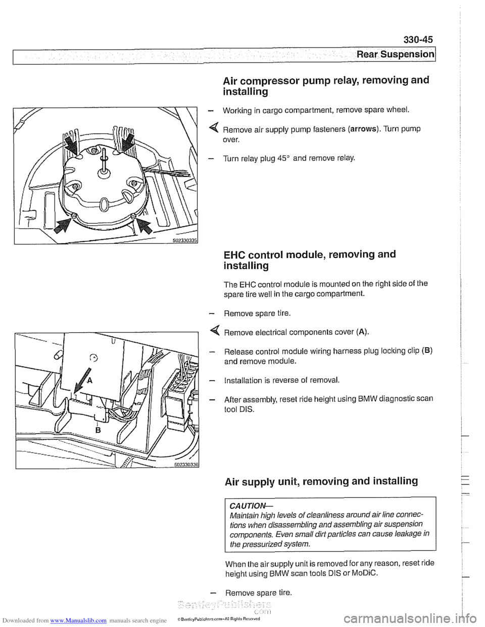
- Working in cargo compartment, remove spare wheel.
4 Remove air supply pump fasteners (arrows). Turn pump
over.
- Turn relay plug 45" and remove relay.
EHC control module, removing and
installing
The EHC control module is mounted on the right side of the
spare tire
well in the cargo compartment.
- Remove spare tire.
4 Remove electrical components cover (A).
- Release control module wiring harness plug loclting clip (B)
and remove module.
- Installation is reverse of removal.
- After assembly, reset ride height using BMW diagnostic scan
tool DIS.
Air supply unit, removing and installing
CAUTION-
Maintain high levels of cleanliness around air line connec-
tions when disassembling and assembling air suspension
components. Even small dirt particles can cause
leakage in
the pressurized system.
When the airsupply unit is removed for any reason, reset ride
height using BMW scan tools DIS or
MoDiC.
- Remove spare tire.
i~B,!n,,ayPubi.l,c~u.c~"~-A~~ R
Page 742 of 1002
Downloaded from www.Manualslib.com manuals search engine
Rear Suspension
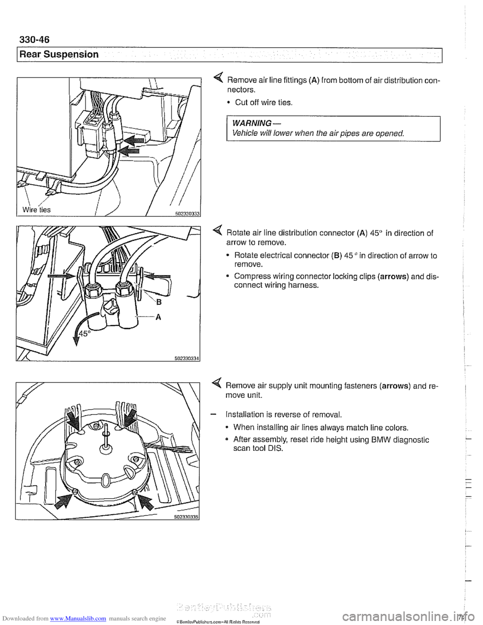
4 Remove air line fittings (A) from bottom of air distribution con-
nectors.
Cut off wire ties.
WARNING-
Vehicle will lower when the air pipes are opened.
4 Rotate air line distribution connector (A) 45" in direction of
arrow to remove.
Rotate electrical connector
(B) 45" in direction of arrow to
remove.
Compress wiring connector locking clips
(arrows) and dis-
connect wiring harness.
< Remove air supply unit mounting fasteners (arrows) and re-
move unit.
- Installation is reverse of removal.
When installing air lines always match line colors.
a After assembly, reset ride height using BMW diagnostic
scan tool DIS.
Page 748 of 1002
Downloaded from www.Manualslib.com manuals search engine
331-4
Final Drive
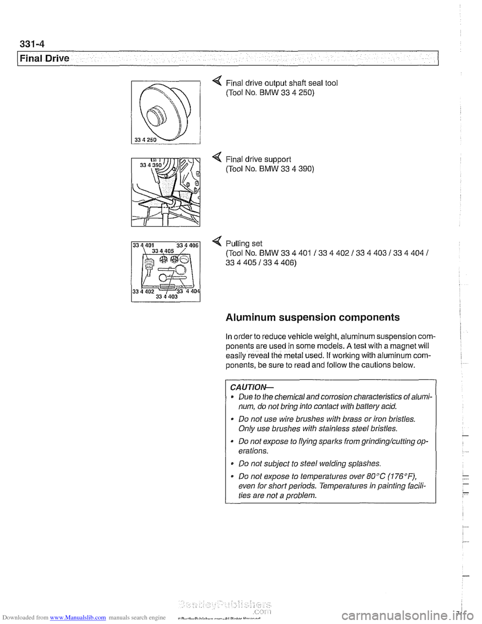
4 Final drive output shaft seal tool
(Tool No.
BMW 33 4 250)
4 Pulling set
(Tool No.
BMW 33 4 401 / 33 4 402 / 33 4 403 133 4 404 /
33 4 405 / 33 4 406)
Aluminum suspension components
In order to reduce vehicle weight, aluminum suspension com-
ponents are
~sed in some models. A tesl wlh a magnet wi.1
eas'ly reveal lhe metal Lseo. If working with a umin~m com-
ponents, be sure to read and follow the cautions below.
CAUTIOI\C
Due to the chemical and corrosion characteristics of alumi-
num, do not bring into contact with battery acid.
Do not use wire brushes with brass or iron bristles.
Only use brushes with stainless steel bristles.
Do not expose to flying sparks from grinding/cutting op-
erations.
Do not subject to steel welding splashes.
Do not expose to temperatures over
80°C (176"F),
even for short periods. Temperatures in painting facili-
ties are not a problem.
Page 749 of 1002
Downloaded from www.Manualslib.com manuals search engine
Final Drive
Final drive, removing and installing
- Raise rear of car.
WARNING-
Make sure that the car is firmly supported on jack stands de-
signed for the purpose. Place the jaclc stands beneath struc-
tural chassis
~oints. Do not i lace iaclc stands under
( suspension barfs.
Remove exhaust system. See 180 Exhaust System.
Disconnect drive shaft from final drive. See
260 Driveshaft.
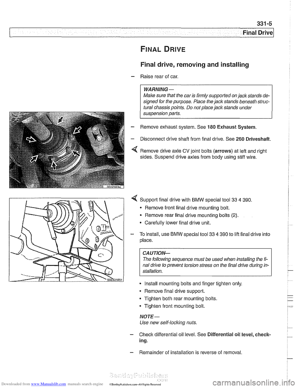
Remove drive axle CV joint bolts (arrows) at left and right
sides. Suspend drive axles from body using stiff wire.
4 Support final drive with BMW special tool 33 4 390.
* Remove front final drive mounting bolt.
Remove rear final drive mounting bolts
(2).
Carefully lower final drive unit.
- To install, use BMW special tool 33 4 390 to lift final drive into
place.
CA UTIOP&
The following sequence must be used when installing the fi-
nal drive to prevent torsion stress on the final drive during in-
Install mounting bolts and finger tighten only.
Remove final drive support.
Tighten both rear mounting bolts.
Tighten front mounting bolt.
NOTE-
Use new self-locking nuts.
- Check differential oil level. See Differential oil level, check-
ing.
- Remainder of installation is reverse of removal.
Page 754 of 1002
Downloaded from www.Manualslib.com manuals search engine
. .
Final Drive Final drive output shaft seals, replacing
- Remove exhaust system (if necessary). See 180 Exhaust
System.
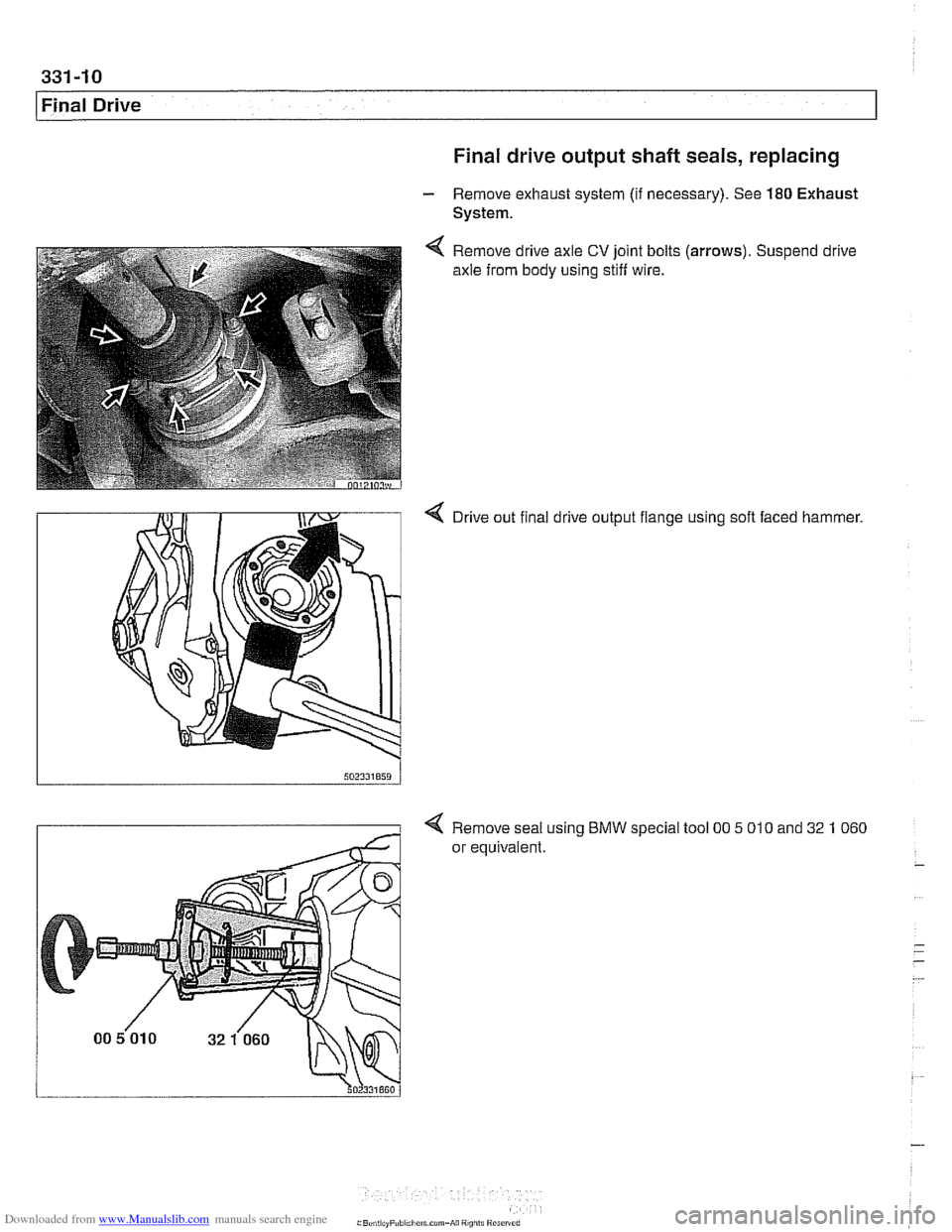
Remove drive axle
CV joint bolts
axle from body using stiff wire. (arrows).
Suspend drive
4 Drive out final drive output flange using soft faced hammer.
4 Remove seal using BMW special tool 00 5 010 and 32 1 060
or equivalent.
Page 764 of 1002
Downloaded from www.Manualslib.com manuals search engine
This repair group covers brake service:
Brake pads, calipers, and disks
Master cylinder, bralte booster, and parking brake
ABS
1 ASC and ABS / DSC component replacement
ABS
1 ASC and ABS 1 DSC system descriptions are covered
in
300 Suspension, Steering and Brakes - General.
Special Tools
BMW requires the use of either the DIS or the MoDiC diag-
nostic tool to safely and completely bleed the
brak~ng and
traction control systems. Read all procedures through before
beginning a job.
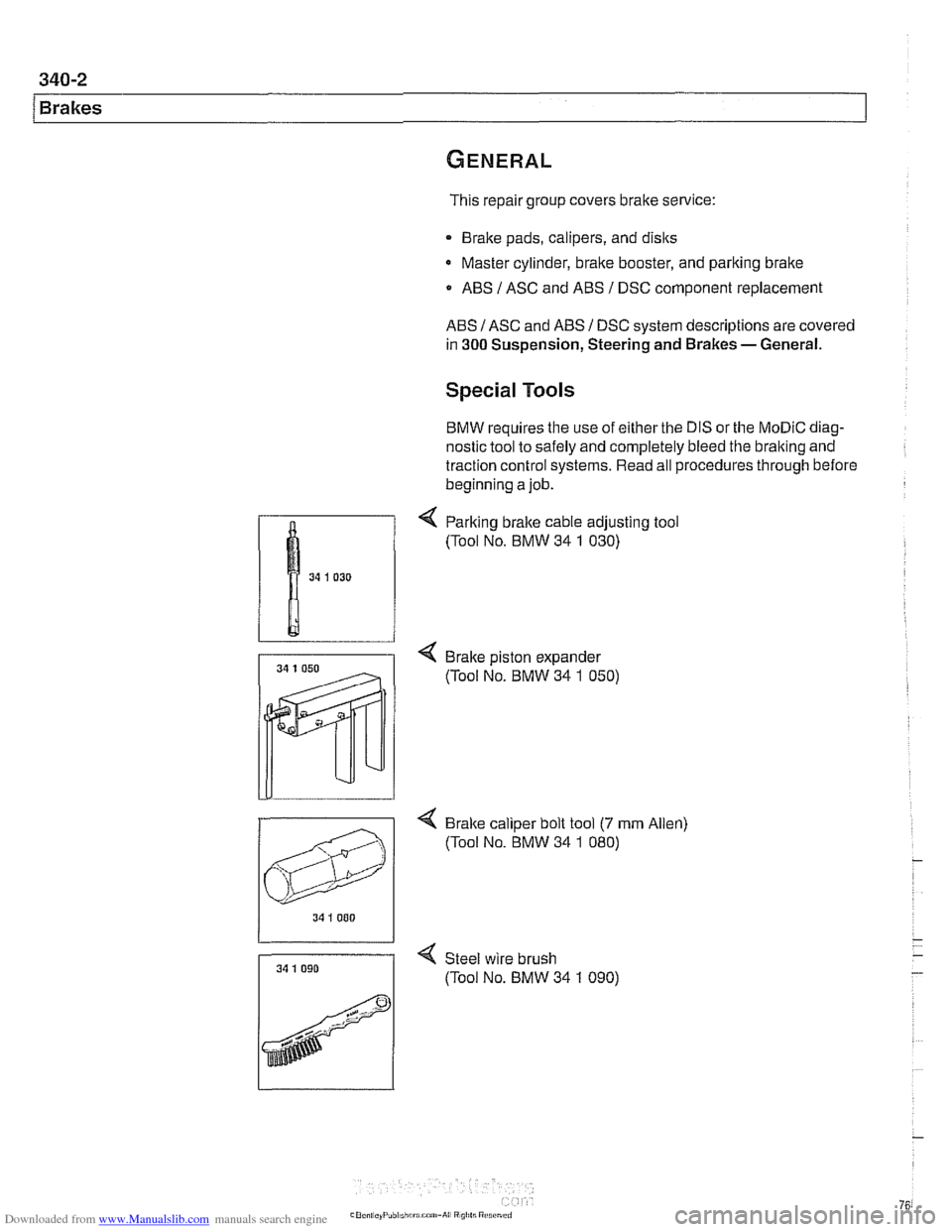
< Parking bralte cable adjusting tool
(Tool No. BMW 34
1 030)
4 Brake piston expander
(Tool No. BMW 34
1 050)
4 Bralte caliper bolt tool (7 mrn Allen)
(Tool No. BMW 34
1 080)
34 I 000
34 1 090 < Steel wire brush
7 (Tool No. BMW 34 1 090)
Page 771 of 1002
Downloaded from www.Manualslib.com manuals search engine
Brakes
Brakes, bleeding
The procedure below requires a BMW Service Tester (DIS-
pluslGTl/MoDiC).
- Determine type of traction control (ASC, DSC with precharge
pump, DSC without precharge pump). Be sure to use correct
specification brake fluid, according to application table below.
Brake fluid applications
ABS I ASC and ABS / DSC models DOT 4 brake fluid
with precharge pump (to 911998)
ABS I DSC models without precharge DOT 4 low viscosity
pump (911998 and later) brake
fluid
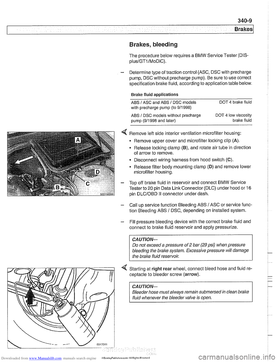
< Remove left side interior ventilation microfilter housing:
Remove upper cover and microfilter loclting clip
(A).
Release locking clamp (B), and rotate air tube in direction
of arrow to remove.
Disconnect wiring harness from hood switch
(C).
Release filter body mounting clamp (D) and remove lower
microfilter housing.
- Top off bralte fluid in reservoir and connect BMW Service
Tester to
20 pin Data Link Connector (DLC) under hood or 16
pin
DLCIOBD I1 connector under dash.
- Call up service function Bleeding ABS / ASC or service func-
tion Bleeding ABS
/ DSC, depending on installed system.
- Fill pressure bleeding device with the correct brake fluid and
connect to brake fluid reservoir and apply pressurize.
Do not exceed a pressure of
2 bar (29 psi) when pressure
bleeding the
brake system. Excessive pressure will damage
4 Starting at right rear wheel, connect bleed hose and fluid re-
ceptacle to bleeder screw (arrow).
CA UTlON-
Bleeder hose must always remain submersed in clean brake
fluid whenever the bleeder valve is open.
Page 776 of 1002
Downloaded from www.Manualslib.com manuals search engine
340-1 4
Brakes
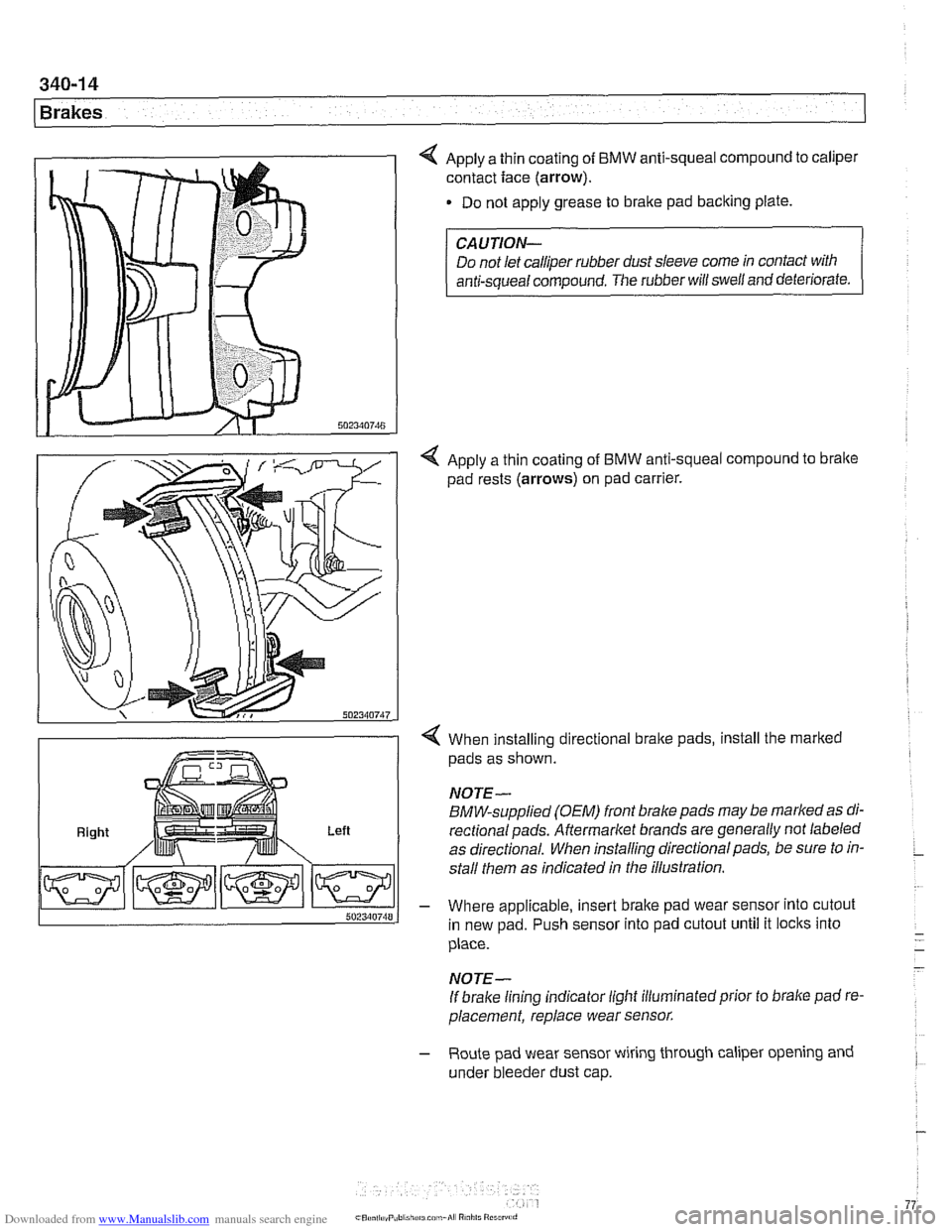
4 Apply a thin coating of BMW anti-squeal compound to caliper
contact face
(arrow).
Do not apply grease to brake pad backing plate.
Right Left
CAUTION-
Do not let calliper rubber dust sleeve come in contact with
anti-squeal compound. The rubber will swell and deteriorate.
4 Apply a thin coating of BMW anti-squeal compound to bralte
pad rests (arrows) on pad carrier.
4 When installing directional brake pads, install the marked
pads as shown.
NOTE-
BMW-supplied (OEM) front brake pads may be marked as di-
rectionalpads. Aftermarket brands are generally not labeled
as directional. When installing directional pads, be sure to in-
stall them as indicated in the illustration.
- Where applicable, insert brake pad wear sensor into cutout
in new pad. Push sensor into pad cutout until it locks into
place.
- -
- NOTE-
If brake lining indicator light illuminatedprior to brake pad re-
placement, replace wear sensor.
- Route pad wear sensor wiring through caliper opening and
under bleeder dust cap.
Page 777 of 1002
Downloaded from www.Manualslib.com manuals search engine
340-1 5
Brakes
- Remainder of installation is reverse of removal.
- Clean brake caliper mounting bolts (7 mm Allen). Replace
ones which are not in perfect condition. Do not grease.
Top up brake fluid to MAX marking.
- Before driving car, pump bralte pedal several times so that
brake pads contact brake rotors.
Check that brake fluid level is correct. Top up if necessary.
Hold ignition key for at least
30 seconds in accessory po-
sition without starting engine. This clears any fault codes in
memory and turns off brake pad warning light.
Tightening torques Brake caliper to pad carrier
(7 mm Allen)
Front caliper
30 Nm (22 It-lb)
- Rear caliper 28 Nm (21 It-lb)
Road wheel to hub
120i 10 Nm (89i7 ft-lb)
Brake rotors, removing and installing
- Raise car and remove wheels
WARNING-
Male sure that the car is firmly supported on jack stands de-
signed for the purpose. Place jack stands beneath structural
chassis points. Do not place jack stands under suspension
parts.
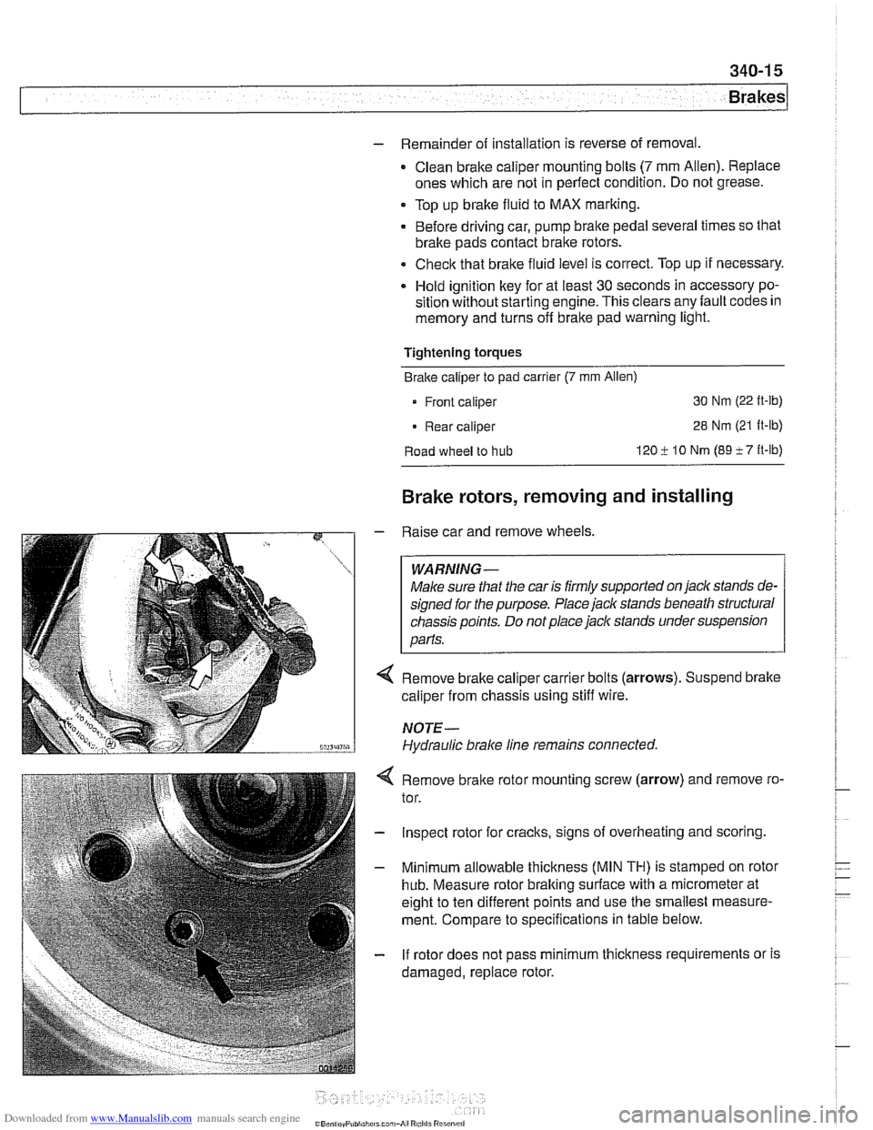
Remove brake caliper carrier bolts (arrows). Suspend brake
caliper from chassis using stiff wire.
NOTE-
Hydraulic brake line remains connected.
4 Remove bralte rotor mounting screw (arrow) and remove ro-
tor.
- Inspect rotor for cracks, signs of overheating and scoring.
- Minimum allowable thickness (MIN TH) is stamped on rotor
hub. Measure rotor braking surface with a micrometer at
eight to ten different points and use the smallest measure-
ment. Compare to specifications in table below.
- If rotor does not pass minimum thickness requirements or is
damaged, replace rotor.