Wir BMW 540i 1997 E39 Workshop Manual
[x] Cancel search | Manufacturer: BMW, Model Year: 1997, Model line: 540i, Model: BMW 540i 1997 E39Pages: 1002
Page 779 of 1002
Downloaded from www.Manualslib.com manuals search engine
Brakes
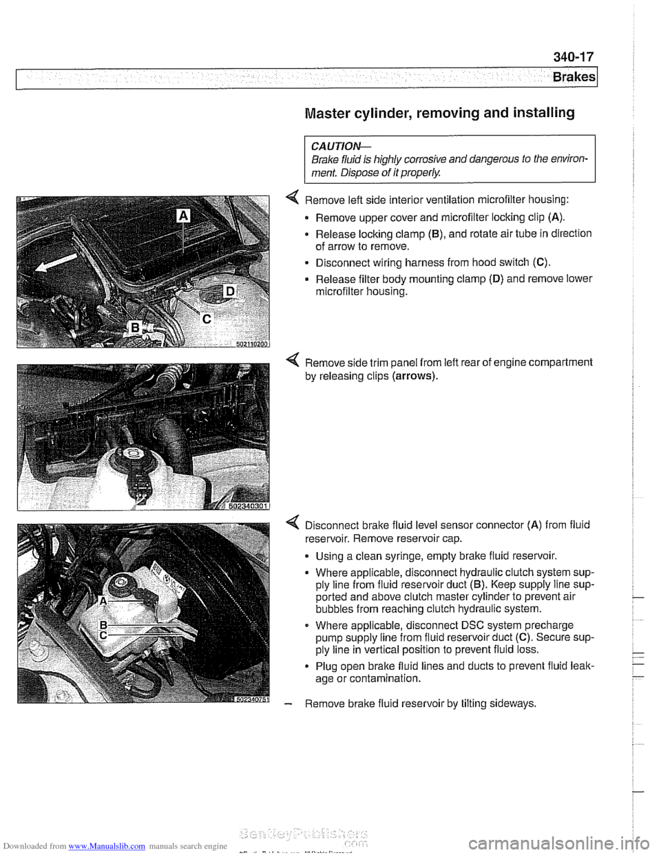
Master cylinder, removing and installing
CAUTlOI\C
Brake fluid is highly corrosive and dangerous to the environ-
ment. Dispose of it properly.
4 Remove left side interior ventilation microfilter housing:
Remove upper cover and microfilter locking clip
(A).
- Release locking clamp (B), and rotate air tube in direction
of arrow to remove.
Disconnect wiring harness from hood switch
(C).
Release filter body mounting clamp (D) and remove lower
microfilter housing.
4 Remove side trim panel from left rear of engine compartment
by releasing clips
(arrows).
4 Disconnect bralte fluid level sensor connector (A) from fluid
reservoir. Remove reservoir cap.
. Using a clean syringe, empty bralte fluid reservoir.
Where applicable, disconnect hydraulic clutch system sup-
ply line from fluid reservoir duct
(5). Keep supply line sup-
ported and above clutch master cylinder to prevent air
bubbles from reaching clutch hydraulic system.
Where applicable, disconnect DSC system precharge
pump supply line from fluid reservoir duct
(C). Secure sup-
ply line in vertical position to prevent fluid loss.
Plug open brake fluid lines and ducts to prevent fluid leak-
age or contamination.
- Remove brake fluid reservoir by tilting sideways.
Page 785 of 1002
Downloaded from www.Manualslib.com manuals search engine
340-23
Brakes
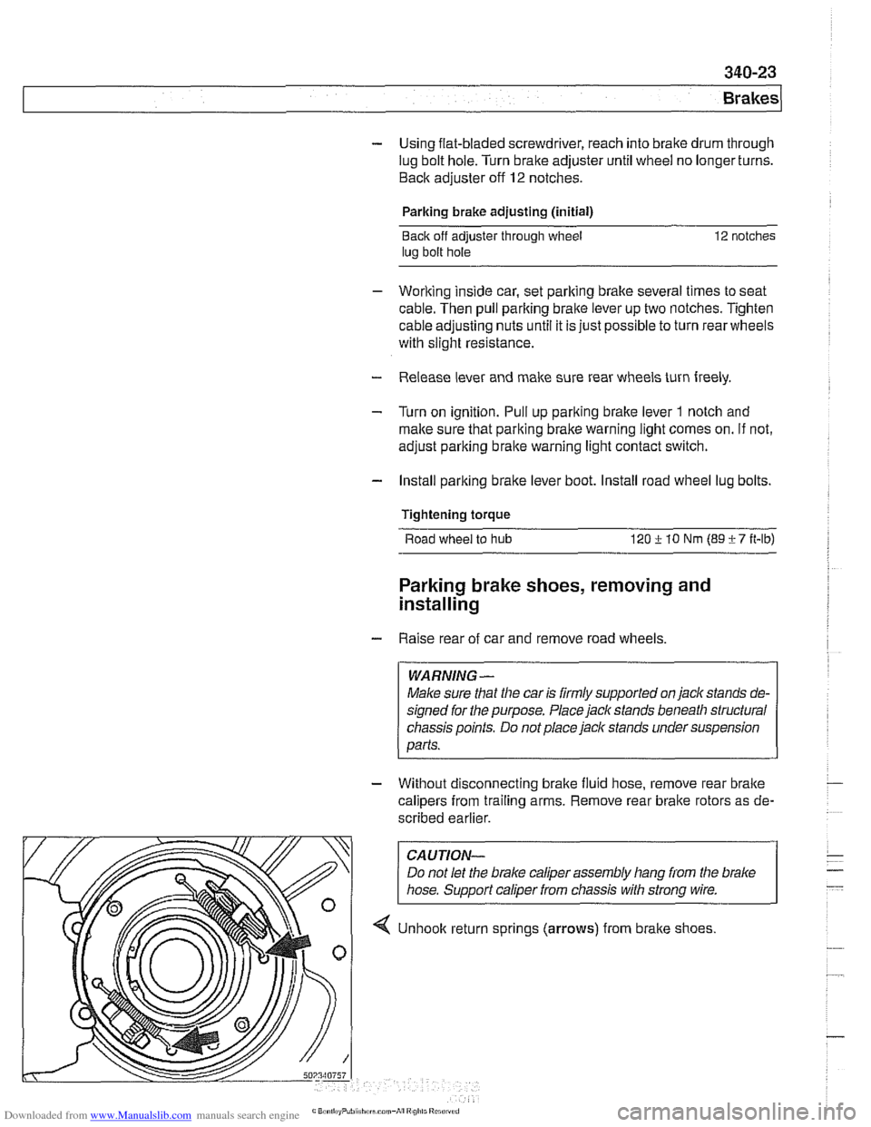
- Using flat-bladed screwdriver, reach into brake drum through
lug bolt hole. Turn brake adjuster until wheel no longer turns.
Back adjuster off
12 notches.
Parking brake adjusting (initial)
Back
off adjuster through wheel
lug bolt hole 12 notches
- Working inside car, set parking brake several times to seat
cable. Then pull parking brake
lever up two notches. Tighten
cable adjusting nuts until it is just possible to turn rear wheels
with slight resistance.
- Release lever and make sure rear wheels turn freely
- Turn on ignition. Pull up parlting brake lever 1 notch and
make sure that parking bralte warning light comes on. if not,
adjust parking bralte warning light contact switch.
- Install parking brake lever boot. Install road wheel lug bolts.
Tightening torque Road
wheel to hub 120 i. 10 Nrn (89 i- 7 ft-lb)
Parking brake shoes, removing and
installing
- Raise rear of car and remove road wheels.
WARNING-
Make sure that the car is firmly supported on jack stands de-
signed for
the purpose. Place jack stands beneath structural
chassis points. Do not place
jaclc stands under suspension
parts.
- Without disconnecting brake fluid hose, remove rear bralte
calipers from trailing arms. Remove rear brake rotors as de-
scribed earlier.
CAUTION-
Do not let the brake caliper assembly hang from the brake
hose. Support caliper from chassis with strong wire.
4 Unhook return sprlngs (arrows) from brake shoes
Page 790 of 1002
Downloaded from www.Manualslib.com manuals search engine
340-28
Brakes
- Remove sensor mounting screws. Lift sensor away from
bracket.
- Installation is reverse of removal.
CAUTION-
Be sure to tighten the DSC acceleration sensor(s) and
mounting bracket, if applicable, to specified torques. The
sensor
is vibration sensitive and subject to cause DSC
malfunctions if installed improperly.
a After replacing the sensor, perform sensor adjustment
using either DIS or
MoDiC under Service Functions
menu.
Tightening
torques
Lateral acceleration I rotational rate sensor 8 Nm (6 R-ib)
to bracket
Sensor bracket to body
8 Nm (6 ft-lb)
DSC steering angle sensor, removing and
installing
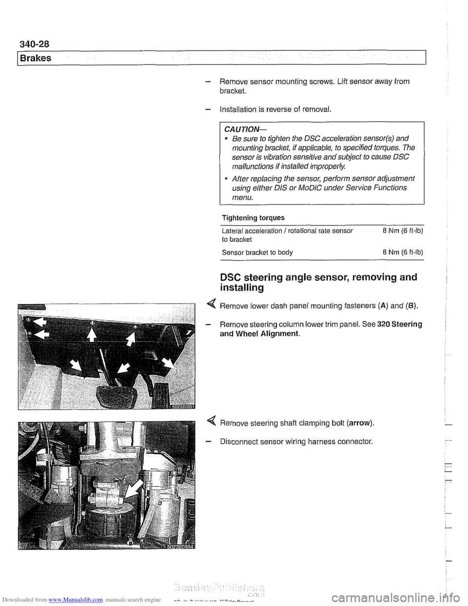
4 Remove lower dash panel mounting fasteners (A) and (5).
- Remove steering column lower trim panel. See 320 Steering
and Wheel Alignment.
Remove steering shaft clamping bolt (arrow).
Disconnect sensor wiring harness connector.
Page 803 of 1002
Downloaded from www.Manualslib.com manuals search engine
400-9
Body-General
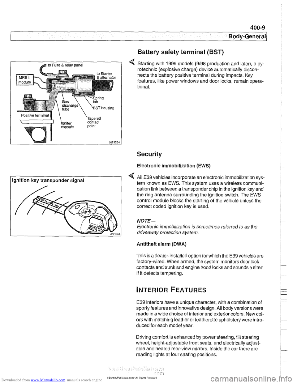
Battery safety terminal
(BST)
4 Starting with 1999 models (9198 production and later), a py-
rotechnic (explosive charge) device automatically discon-
nects the battery positive terminal during impacts. Key
features,
like power windows and door locks, remain opera-
tional.
Security
Electronic immobilization (EWS)
Ignition key transponder signal All
E39 vehicles incorporate an electronic immobilization sys-
tem known as EWS. This svstem uses a wireless comrnuni-
cation link between a transponder chip in the ignition key and
the ring antenna surrounding the ignition switch. The EWS
control module blocks the starting of the vehicle unless the
correct coded ignition key is used.
NOTE-
Electronic immobilization is sometimes referred to as the
driveaway protection system.
Antitheft alarm (DWA)
This is adealer-installed option for which the E39 vehicles are
factory-wired. When armed, the system monitors door
loci(
contacts and trunk and engine hood locks and sounds a siren
if it detects tampering.
E39 interiors have a unique character, with a combination
of
sporty features and innovativedesign. All body versions were
made in a wide choice of interior and exterior colors. New col-
ors with matching leather or leatherette upholstery were intro-
duced for each model year.
Driving
comfort is enhanced by power steering, tilt steering
wheel, height-adjustable front seats, and electrically adjust-
able and heated rear-view mirrors. Inside the car there are
reading lights at four seating positions.
Page 813 of 1002
Downloaded from www.Manualslib.com manuals search engine
Fenders, Engine ~ood/
Hood, removing and installing
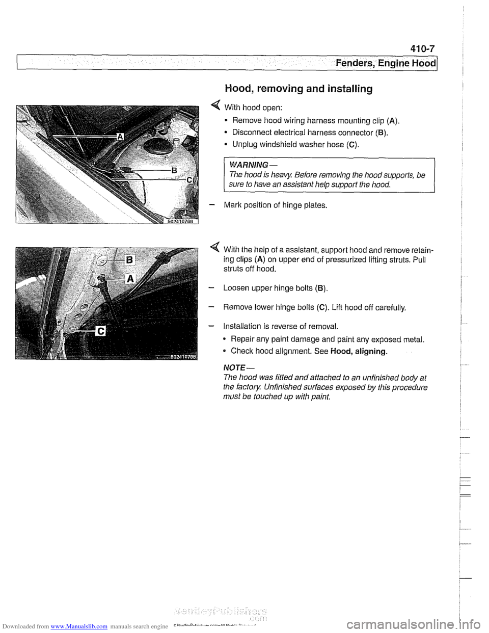
With hood open:
Remove hood wiring harness mounting clip
(A)
Disconnect electrical harness connector (B).
Unplug windshield washer hose (C).
WARNING-
The hood is heavy Before removing the hoodsupports, be
sure to have an assistant help
support the hood.
Mark position of hinge plates.
With the help of a assistant, support hood and remove retain-
ing clips
(A) on upper end of pressurized lifting struts. Pull
struts off hood.
Loosen upper hinge bolts
(B)
Remove lower hinge bolts (C). Lift hood off carefully.
Installation is reverse of removal.
* Repair any paint damage and paint any exposed metal
Check hood alignment. See
Hood, aligning.
NOTE-
The hood was fitted and attached to an unfinished body at
the factory Unfinished
sun'aces exposed by this procedure
must be touched up with paint,
Page 821 of 1002
Downloaded from www.Manualslib.com manuals search engine
411-3
Doors
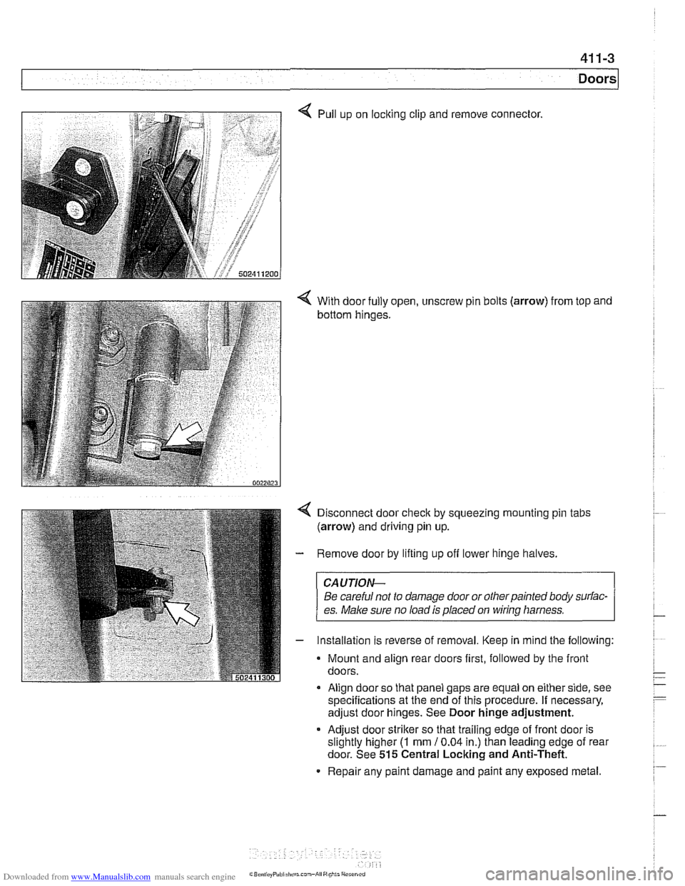
4 Pull up on locking clip and remove connector.
4 With door fully open, unscrew pin bolts (arrow) from top and
bottom hinges.
Disconnect door
check by squeezing mounting pin tabs
(arrow) and driving pin up.
Remove door by lifting up off lower hinge halves.
CAUJION-
Be careful not to damage door or otherpainted body surfac-
es.
Make sure no load is placed on wirinq harness.
Installation is reverse of removal. Keep in mind the following:
Mount and align rear doors first, followed by the front
doors.
Align door so that panel gaps are equal on either side, see
specifications at the end of this procedure. If necessary,
adjust door hinges. See Door hinge adjustment.
* Adjust door striker so that trailing edge of front door is
slightly higher
(I mm 10.04 in.) than leading edge of rear
door. See
515 Central Locking and Anti-Theft.
Repair any paint damage and paint any exposed metal.
Page 825 of 1002
Downloaded from www.Manualslib.com manuals search engine
WARNING -
E39 cars are fitted with side-impact airbags in the front doors
and optional side impact
airbags in the rear doors. When
servicing doors, always disconnect the negative
(-) battery
terminal. See
721 Airbag System (SRS) for cautions and
procedures relating to the
airbag system.
Door trim panel, removing and installing
Disconnect negative (-) battery cable.
CAUTION--
Prior to disconnecting the battem read the batfew discon-
nection cautions given in
001 General Cautions and warn-
ings.
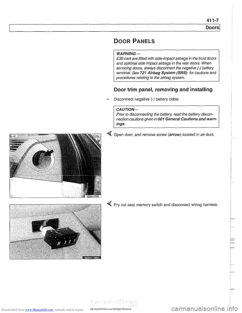
Q Open door, and remove screw (arrow) located
in air
duct.
< Pry out seat memory switch and disconnect wiring harness.
Page 827 of 1002
Downloaded from www.Manualslib.com manuals search engine
I
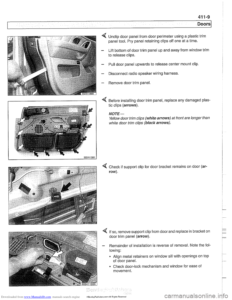
< Unclip door panel from door perimeter using a plastic trim
panel tool. Pry panel retaining clips off one at a time.
- Lift bottom of door trim panel up and away from window trim
to release clips.
- Pull door panel upwards to release center mount clip.
- Disconnect radio speaker wiring harness.
- Remove door trim panel.
< Before installing door trim panel, replace any damaged plas-
tic clips (arrows).
NOTE-
Yellow door trim clips (white arrows) at front are longer than
white door trim clips (blaclc arrows).
4 Checlt if support clip for door bracltet remains on door (ar-
row).
4 If so, remove support clip from door and replace in bracltet on
door trim panel (arrow).
- Remainder of installation is reverse of removal. Note the fol-
lowing:
Align metal retainers on window sill with openings on top
of door panel.
Checlc door-lock mechanism and window for ease of
movement.
Page 831 of 1002
Downloaded from www.Manualslib.com manuals search engine
Trunk Lid, Tailgate
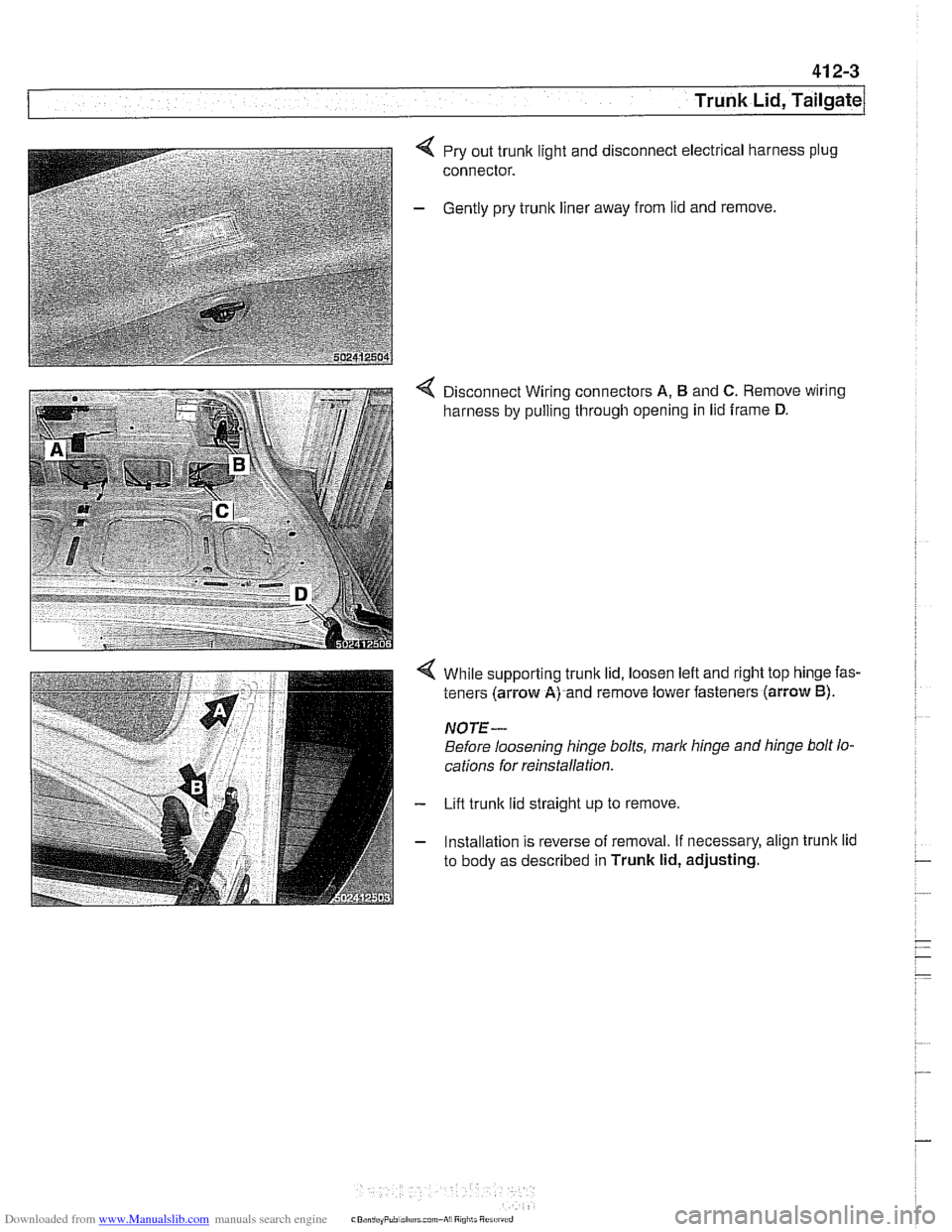
4 Pry out trunk light and disconnect electrical harness plug
connector.
- Gently pry trunk liner away from lid and remove.
4 Disconnect Wiring connectors A, B and C. Remove wiring
harness by pulling through opening in lid frame
D.
While supporting trunk lid, loosen left and right top hinge fas-
teners (arrow
A) and remove lower fasteners (arrow B).
NOTE-
Before loosening hinge bolts, mark hinge and hinge bolt lo-
cations for
reins~alla~on
Lift trunk lid straight up to remove.
Installation is reverse of removal. If necessary, align trunk lid
to body as described in
Trunk lid, adjusting.
Page 838 of 1002
Downloaded from www.Manualslib.com manuals search engine
.-
l~runk Lid, Tailgate
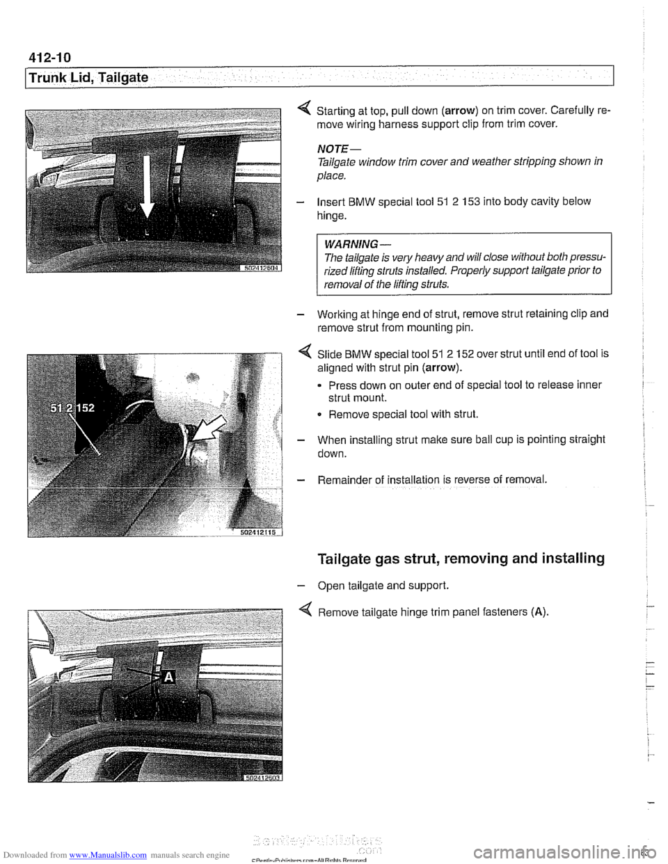
Starting at top, pull down (arrow) on trim cover. Carefully re-
move wiring harness support clip from trim cover.
NOTE-
Tailgate window trim cover and weather stripping shown in
place.
Insert BMW special tool 51 2
153 into body cavity below
hinge.
WARNING-
Tlie tailgate is ve!y heavy and will close without both pressu-
rized liftinq struts installed. Properly support
tailgafe prior to r
1 removal of the lifting struts.
- Working at hinge end of strut, remove strut retaining clip and
remove strut from mounting pin.
Slide BMW special tool 51 2 152 over strut until end of tool is
aligned with strut pin
(arrow).
Press down on outer end of special tool to release inner
strut mount.
Remove special tool with strut.
When installing strut make sure ball cup is pointing straight
down.
Rema~nder of installation 1s reverse of removal.
Tailgate gas strut, removing and installing
- Open tailgate and support.
Remove tailgate hinge trim panel fasteners
(A).