Wir BMW 540i 1997 E39 Workshop Manual
[x] Cancel search | Manufacturer: BMW, Model Year: 1997, Model line: 540i, Model: BMW 540i 1997 E39Pages: 1002
Page 673 of 1002
Downloaded from www.Manualslib.com manuals search engine
320-1 5
Steering and Wheel ~li~nmentl
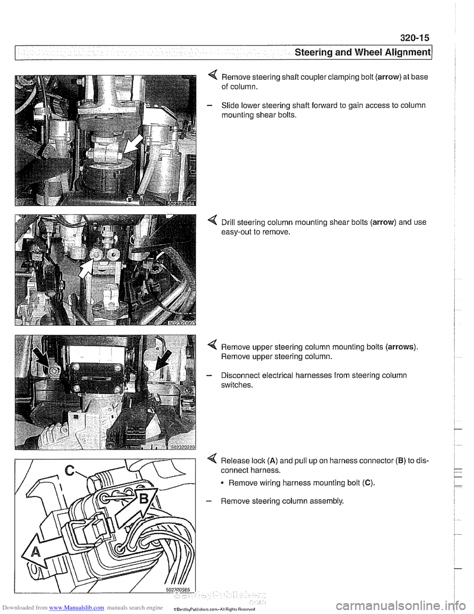
Remove steering shaft coupler clamping bolt (arrow) at base
of column.
Slide lower steering shaft forward to gain access to column
mounting shear bolts.
< Drill steering column mounting shear bolts (arrow) and use
easy-out to remove.
Remove upper steering column mounting bolts
(arrows).
Remove upper steering column.
Disconnect electrical harnesses from steering column
switches.
4 Release lock (A) and pull up on harness connector
connect harness.
Remove wiring harness mounting bolt
(C).
- Remove steering column assembly.
(B) to dis.
Page 674 of 1002
Downloaded from www.Manualslib.com manuals search engine
I Steering and Wheel Alignment
- Installation is reverse of removal, noting the following:
Replace shear bolts at steering column mounting bracket.
Tighten until bolt heads shear off.
Make sure
interlock cable snaps into place.
When installing column top trim panel, replace expansion
nut for trim retaining screw.
NOTE-
The steering angle sensor must be coded using a BMW scan
tool if it has been replaced.
A steering angle offset check
must then be carried out using the same
BMW scan tool.
CAUTION-
Check steering system for freedom of movement through en-
tire steering column
adiustment range.
Tightening torques Steering shaft coupler
to steering shaft 25 Nm (18 ft-lb)
(replace bolt)
Steering column to body
22 Nm (16 ft-lb)
Steering column adjustment motors,
removing and installing
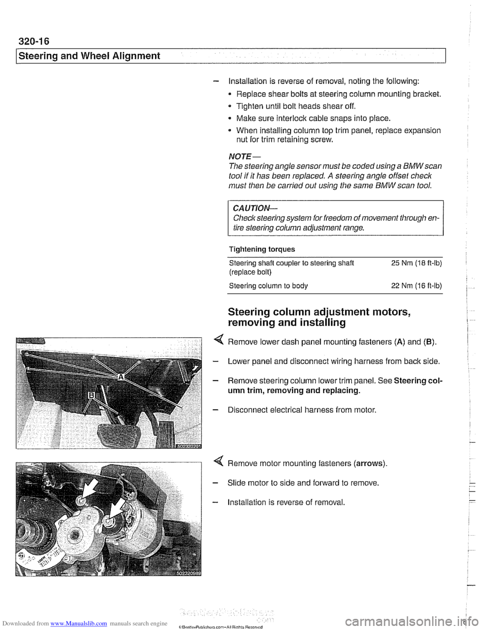
Remove lower dash panel mounting fasteners (A) and (B).
- Lower panel and disconnect wiring harness from back side.
- Remove steering column lower trim panel. See Steering col-
umn trim, removing and replacing.
- Disconnect electrical harness from motor.
Remove motor mounting fasteners (arrows)
Slide motor to side and forward to remove.
Installation is reverse of removal.
Page 698 of 1002
Downloaded from www.Manualslib.com manuals search engine
330-2
I Rear Suspension
This repair group covers removal and replacement of E39
rear suspension components. A general description of sus-
pension systems and ride height specifications can be found
in 300 Suspension, Steering and Brakes - General.
CAUTIOI\C
Some E39 models are equipped with aluminum suspen-
sion components. The following cautions apply:
Due to the chemical and corrosion characteristics of
aluminum, do not bring into contact with battery acid.
- Do not clean with wire brushes with brass or iron bris-
tles. Only use brushes with stainless steel bristles.
Do not expose to flying
sparl~s from grinding/cutting op-
erations.
* Do not subject to steel welding splashes.
0 Do not expose to temperatures over 80°C (176°F).
even for shortperlods. Temperatures in painting facili-
ties are not a problem.
Special tools
Special service tools are required for some of the work de-
scribed in this repair group. Most of these tools are special-
ized press jigs and pullers that might be replaced by standard
pullers of various sizes.
Read the procedures through before beginning any job.
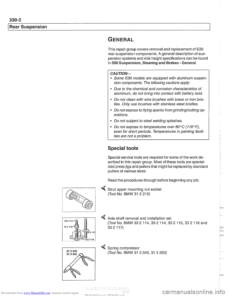
< Strut upper mounting nut socket
(Tool No. BMW
31 2 21 0)
I Axle shaft removal and installation set
Spring compressor (Tool No. BMW
31 3 340.31 3 350)
Page 707 of 1002
Downloaded from www.Manualslib.com manuals search engine
330-1 1
Rear Suspension
Coil spring, removing and installing
Raise car and remove rear wheels.
WARNING-
Make sure the car is firmly supported on jack stands de-
signed for the purpose. Place jack stands underneath struc-
tural chassis points. Do not place jack stands under
suspension parts.
- Remove brake caliper and brake disc. Hang brake caliper
aside with stiff wire. Do not disconnect
bralte fluid hose. See
340 Brakes.
- Remove exhaust system. See 180 Exhaust System.
- Disconnect driveshafl from final drive. See 260 Driveshaft.
- Detach parking bralte cables from mounting bracltets on sub-
frame.
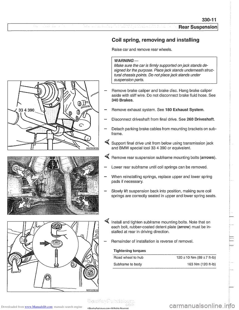
< Support final drive unit from below using transmission jack
and
BMW special tool 33 4 390 or equivalent.
Remove rear suspension
subframe mounting bolts (arrows).
Lower rear
subframe until coil springs can be removed.
When reinstalling springs, replace upper and lower spring
pads if necessary.
Slowly lift suspension
back into position, making sure coil
springs are correctly seated in upper and lower spring seats.
Install and tighten
subframe mounting bolts. Note that on
each bolt, rubber-coated detent plate (arrow) must be in-
stalled at rear in driving direction
- Remainder of installation is reverse of removal
Tightening torques Road wheel
to hub 12OilO Nm (89i-7 ft-lb)
Subframe to body 163 Nm (120 ft-lb)
Page 719 of 1002
Downloaded from www.Manualslib.com manuals search engine
330-23
Rear Suspension
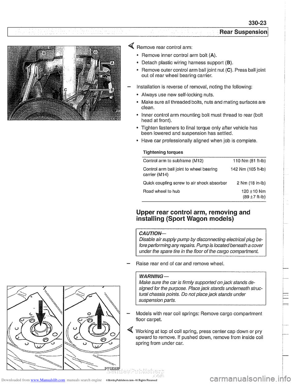
Remove rear control arm:
Remove inner control arm bolt
(A).
Detach plastic wiring harness support (B).
* Remove outer control arm ball joint nut (C). Press ball joint
out of rear wheel bearing carrier.
Installation is reverse of removal, noting the following:
Always use new self-locking nuts.
Malte sure all threaded bolts, nuts and mating surfaces are
clean.
Inner control arm mounting bolt must thread to rear (bolt
head at front).
Tighten fasteners to final torque only afler vehicle has
been lowered and suspension has settled.
Have car professionally aligned when job is complete.
Tightening
torques
Control arm to subframe (M12) 110 Nm (81 ft-ib)
Control arm
ball joint to wheel bearing 142 Nm (105 ft-lb)
carrier
(M14)
Quick coupling screw to air shock absorber
2 Nm (18 in-lb)
Road wheel
to hub 120-flONm
(89 i7 ft-lb)
Upper rear control arm, removing and
installing (Sport Wagon models)
CAUTIOG
Disable air supply pump by disconnecting electrical plug be-
fore
perlorming any repairs. Pump is located beneath a cover
under the spare tire in the floor of the
carqo compartment.
- Raise rear end of car and remove wheel.
WARNING -
Make sure the car is firmly supported on jaclc stands de-
signed for the purpose.
Place jaclc stands underneath struc-
tural chassis points. Do not place jack stands under
suspension parts.
Models with rear coil springs: Remove cargo compartment
floor carpet.
Worlting at top of coil spring, press center cap down or pry
upward to remove. If pushed down, remove from inside coil
spring from under car.
Page 721 of 1002
Downloaded from www.Manualslib.com manuals search engine
330-25
Rear Suspension
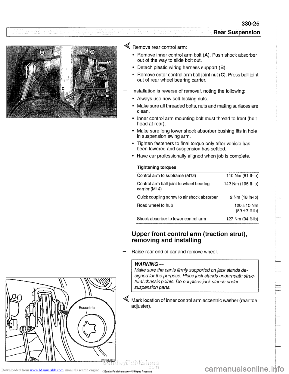
Remove rear control arm:
Remove inner control arm bolt
(A). Push shock absorber
out of the way to slide bolt out.
Detach plastic wiring harness support
(B).
Remove outer control arm ball joint nut (C). Press ball joint
out of rear wheel bearing carrier.
Installation is reverse of removal, noting the following:
* Always use new self-locking nuts.
Maite sure
ail threaded bolts, nuts and mating surfaces are
clean.
Inner control arm mounting bolt must thread to front
(bolt . head at rear).
Make sure long lower shock absorber bushing fits in hole
in suspension swing arm.
* Tighten fasteners to final torque only after vehicle has
been lowered and suspension has settled.
Have car professionally aligned when job is complete.
Tightening torques Control arm to
subframe (M12) 110 Nm (81 ft-ib)
Control arm ball joint to wheel bearing
142 Nm (105 ft-lb)
carrier
(M14)
Quick coupling screw to air shocit absorber
2 Nm (18 in-lb)
Road wheel to hub
Shoclc absorber to lower control arm 127 Nm (94 it-lb)
Upper front control arm (traction strut),
removing and installing
- Raise rear end of car and remove wheel.
WARNING-
Maice sure the car is firmly supported on jack stands de-
signed for the purpose. Place
jack stands underneath struc-
tural chassis points. Do not place jack stands under
< Mark location of inner control arm eccentric washer (rear toe
Page 722 of 1002
Downloaded from www.Manualslib.com manuals search engine
330-26
/ Rear Suspension
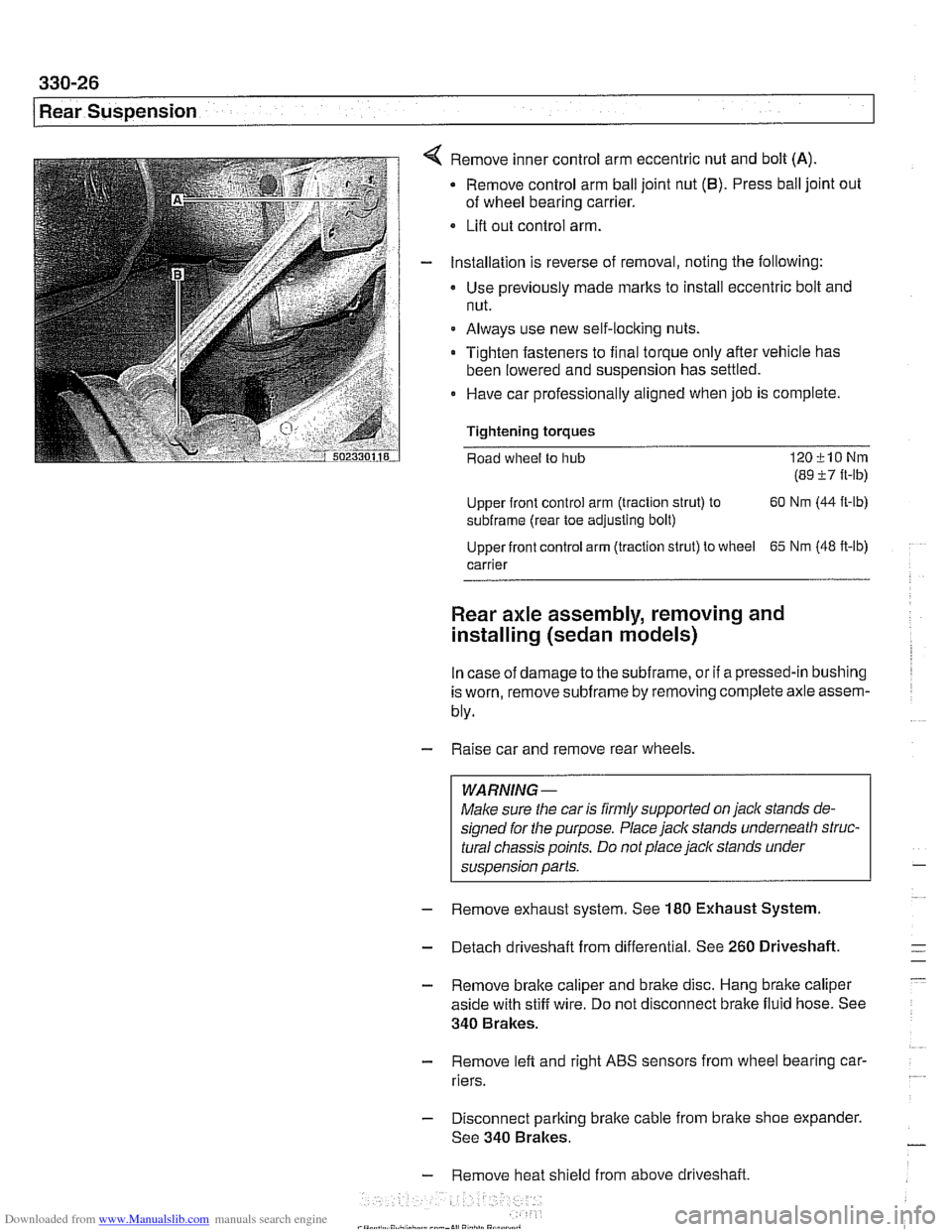
Remove inner control arm eccentric nut and bolt (A)
Remove control arm ball joint nut (6). Press ball joint out
of wheel bearing carrier.
Lifl out control arm.
Installation is reverse of removal, noting the following:
Use previously made
marks to install eccentric bolt and
nut.
Always use new self-locking nuts.
Tighten fasteners to final torque only after vehicle has
been lowered and suspension has settled.
0 Have car professionally aligned when job is complete.
Tightening
torques
Road wheel to hub 120klONm
(89 i7 ft-lb)
Upper front control arm (traction strut) to 60
Nm (44
ft-lb)
subframe (rear toe adjusting bolt)
Upper front control arm (traction strut) to wheel
65 Nm (48 ft-lb)
carrier
Rear axle assembly, removing and
installing (sedan models)
In case of damage to the subframe, or if a pressed-in bushing
is worn, remove
subframe by removing complete axle assem-
bly.
- Raise car and remove rear wheels.
WARNING-
Make sure the car is firmly supported on jack stands de-
signed for the purpose. Place jack stands underneath struc-
tural chassis points. Do not place
jack stands under
suspension parts.
- Remove exhaust system. See 180 Exhaust System
- Detach driveshaft from differential. See 260 Driveshaft.
- Remove brake caliper and brake disc. Hang brake caliper
aside with stiff wire. Do not disconnect brake fluid hose. See
340 Brakes.
- Remove lefl and right ABS sensors from wheel bearing car-
riers.
- Disconnect parking brake cable from brake shoe expander.
See 340 Brakes.
- Remove heat shield from above driveshaft.
Page 725 of 1002
Downloaded from www.Manualslib.com manuals search engine
Rear Suspension
- Remove exhaust system. See 180 Exhaust System.
- Detach driveshaft from differential. See 260 Driveshaft.
- Remove brake caliper and brake disc. Hang brake caliper
aside with stiff wire. Do not disconnect brake fluid hose. See
340 Brakes.
- Remove left and right ABS sensors from wheel bearing car-
riers.
Disconnect parking brake cable from brake shoe expander.
See 340 Brakes.
Remove heat shield from above driveshaft
If equipped, remove ride height sensor connectors
CAUTION-
Models with air springs: Disable air supply pump by discon-
necting electrical plug before performing any repairs. Pump is
locatedbeneath a coverunder
thespare tire in the floorof the
carqo compartment.
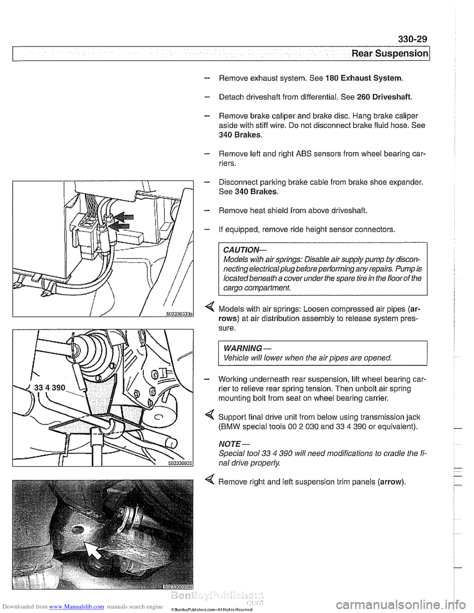
Models with air springs: Loosen compressed air pipes (ar-
rows) at air distribution assembly to release system pres-
sure.
WARNING -
Vehicle will lower when the air pipes are opened. 1
- Working underneath rear suspension, lift wheel bearing car-
rier to relieve rear spring tension. Then unbolt air spring
mounting bolt from seat on wheel bearing carrier.
4 Support final drive unit from below using transmission jack
(BMW special tools 00 2 030 and 33 4 390 or equivalent).
NOTE-
Special tool 33 4 390 will need modifications to cradle the fi-
nal drive properly
4 Remove right and left suspension trim panels (arrow),
Page 728 of 1002
Downloaded from www.Manualslib.com manuals search engine
I Rear Suspension
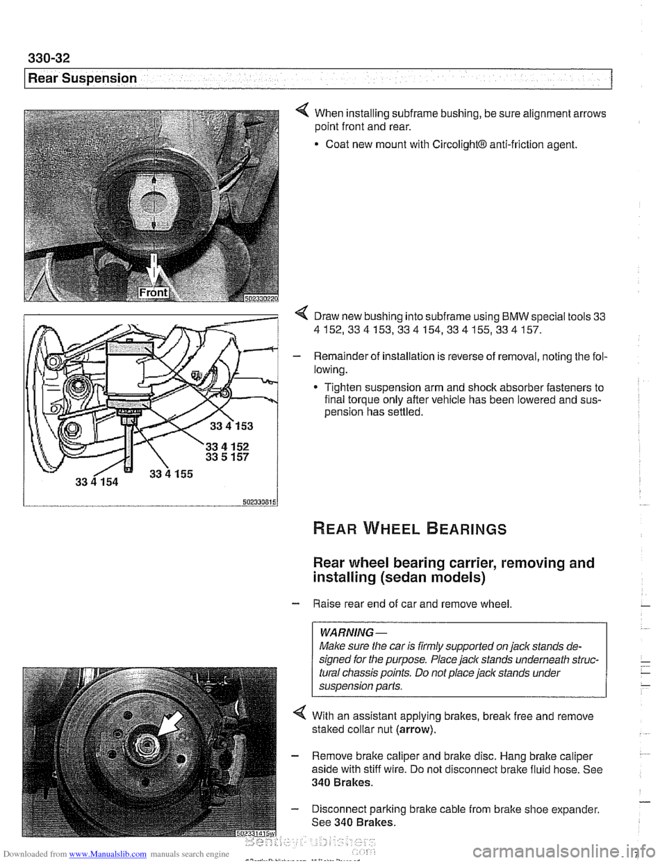
4 When installing subframe bushing, be sure alignment arrows
point front and rear.
Coat new mount with
CircolightB anti-friction agent.
< Draw new bushing into subframe using BMW special tools 33
4152,334153,334154,334155,334157.
- Remainder of installation is reverse of removal, noting the fol-
lowing.
* Tighten suspension arm and shock absorber fasteners to
final torque only after vehicle has been lowered and
sus-
oension has settled.
Rear wheel bearing carrier, removing and
installing (sedan models)
- Raise rear end of car and remove wheel
WARNING-
Make sure the car is firmly supported on jaclc stands de-
signed for the purpose. Place
jaclc stands underneath struc-
tural chassis points. Do not place jaclc stands under
suspension parts.
4 With an assistant applying brakes, break free and remove
staked collar nut (arrow).
- Remove brake caliper and brake disc. Hang brake caliper
aside with stiff wire. Do not disconnect brake fluid hose. See
340 Brakes.
- Disconnect parking brake cable from brake shoe expander.
See 340 Brakes.
Page 733 of 1002
Downloaded from www.Manualslib.com manuals search engine
Rear suspension/
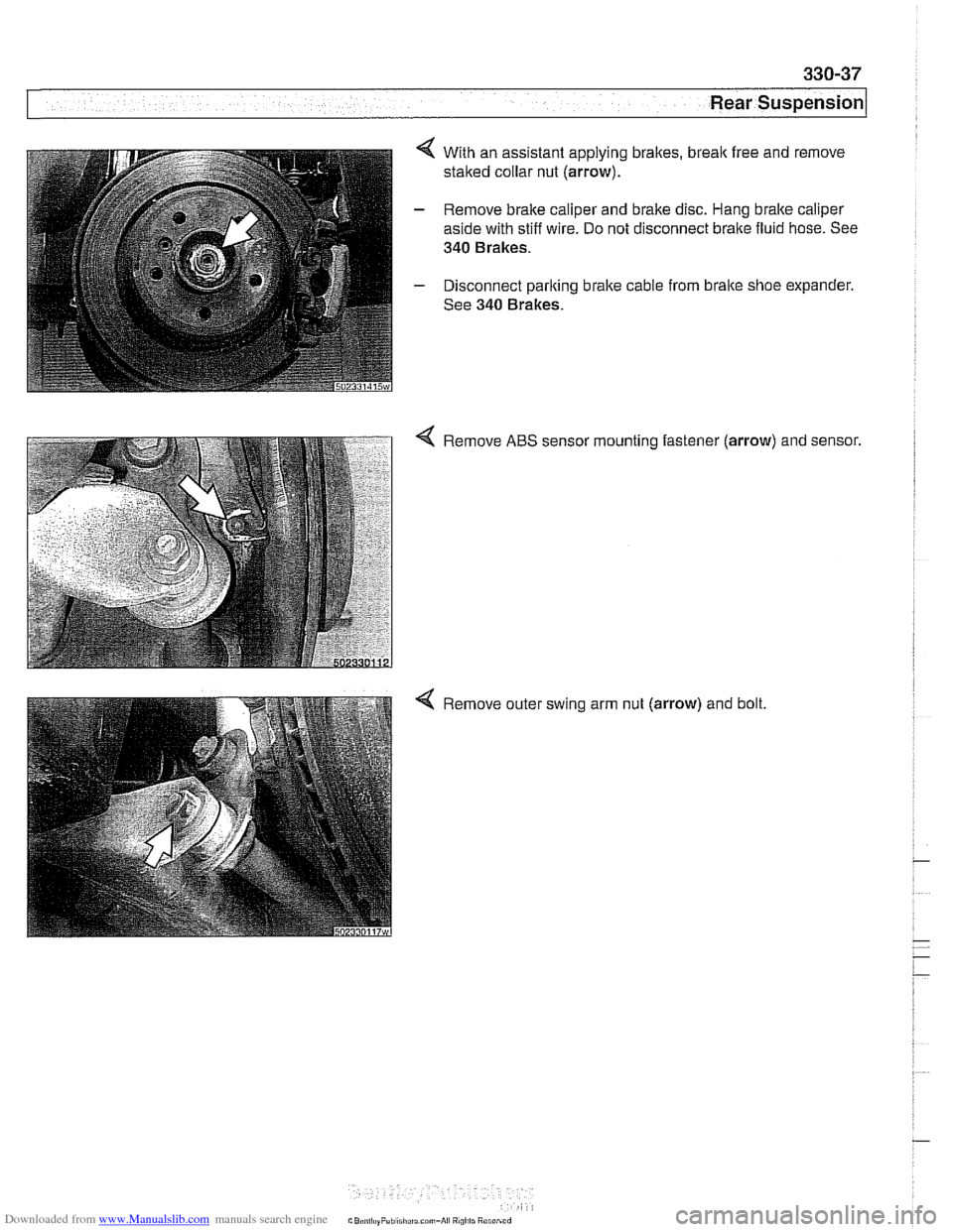
4 With an assistant applying brakes, break free and remove
staked collar nut (arrow).
- Remove brake caliper and brake disc. Hang bralte caliper
aside with stiff wire. Do not disconnect brake fluid hose. See
340 Brakes.
- Disconnect parking brake cable from brake shoe expander.
See 340 Brakes.
Remove ABS sensor mounting fastener
(arrow) and sensor.
Remove outer swing arm nut (arrow) and bolt.