replacing BMW 540i 1997 E39 Owner's Manual
[x] Cancel search | Manufacturer: BMW, Model Year: 1997, Model line: 540i, Model: BMW 540i 1997 E39Pages: 1002
Page 267 of 1002

Downloaded from www.Manualslib.com manuals search engine
Camshaft Timing chain1
Tap locating dowels into cover until they protrude 2 to 3 mm
from sealing surface.
- Using new gaskets, install lower timing chain cover:
Tap cover into position to engage dowels.
Install timing chain cover fasteners and tighten to
5 Nm (44
in-lb).
Drive dowels in flush to front of cover.
. Tighten cover mounting bolts alternately and in stages.
Install cylinder head to timing chain cover fasteners and
tighten.
Tightening torques Lower timing chain cover to block
M7 15 Nm (1 1 ft-lb)
ME 20 Nm (15 it-lb)
- Replace front crankshaft radial seal. See Crankshaft oil
seal, front, replacing
(M52 engine).
Install engine oil pan using
a new gasket. See 119 Lubrica-
tion System.
Mount primary timing chain sprocket to primary
cha~n so that
arrow on sprocket faces up. Mount sprocket to camshafl so
that tapped holes in camshaft are on left side of elongated
holes in sprocket.
4 Install adjustable timing chain tensioner (BMW special tool
11 4 220). Thread tool in finger tight until slack is removed
from chain.
NOTE-
BMW special tool 11 4 220 is an adjustable timing chain ten-
sioner that simulates the function of the hydraulic tensioner.
- Check that elongated holes in primary sprocket are centered
to bolt holes in camshafl and chain is free of slack.
- Install secondary timing chain guide and secondary chain
tensioner. Tighten mounting bolts (tensioner remains
locited
down).
F81.,,l,ryT-iib.l>nii,:oni-Aii Ri"ilti R
Page 293 of 1002
Downloaded from www.Manualslib.com manuals search engine
... -.
rpp- --- Camshaft Timing Chain1
Timing chains, installing
(M52 TU and M54 engines)
CAUTIOI\C
The procedure outlined below assumes that the camshaits
are lockedin the
TDC installation position with speciallocling
tools as shown earliel:
- inspect timing chain sprockets. Inspect guide rail and ten-
sioner rail for damage. Replace any part that is worn
or dam-
aged.
NOTE-
If any sprockets are being replaced due to wear, the chain
should also be replaced.
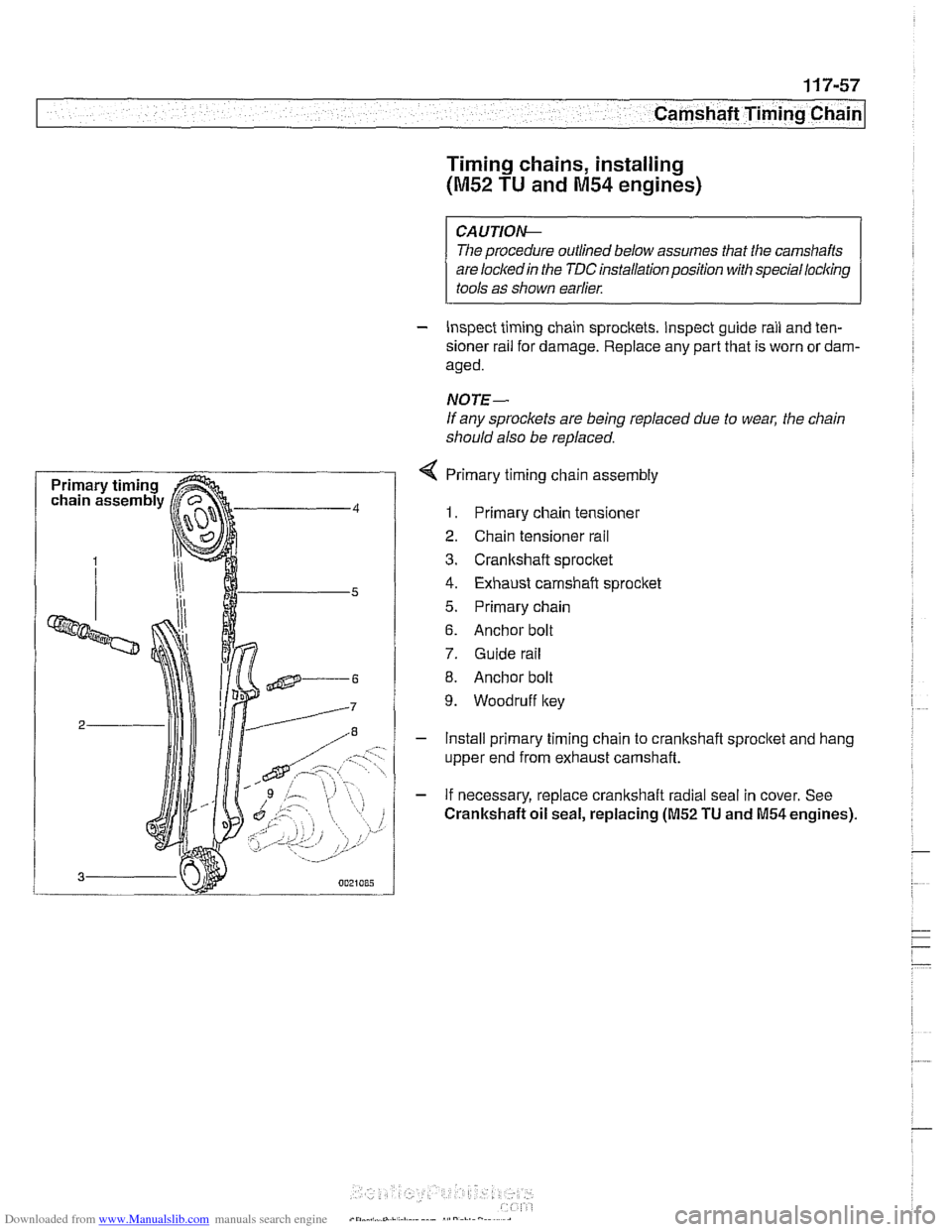
4 Primary timing chain assembly
1. Primary chain tensioner
2. Chain tensioner rail
3. Cranltshaft sprocket
4. Exhaust camshaft sprocket
5. Primary chain
6. Anchor bolt
7. Guide rail
8. Anchor bolt
9. Woodruff key
- Install primary timing chain to crankshaft sprocltet and hang
upper end from exhaust camshaft.
- If necessary, replace crankshaft radial seal in cover. See
Crankshaft oil seal, replacing (M52 TU and M54 engines).
Page 311 of 1002
Downloaded from www.Manualslib.com manuals search engine
Camshaft Timing Chain1
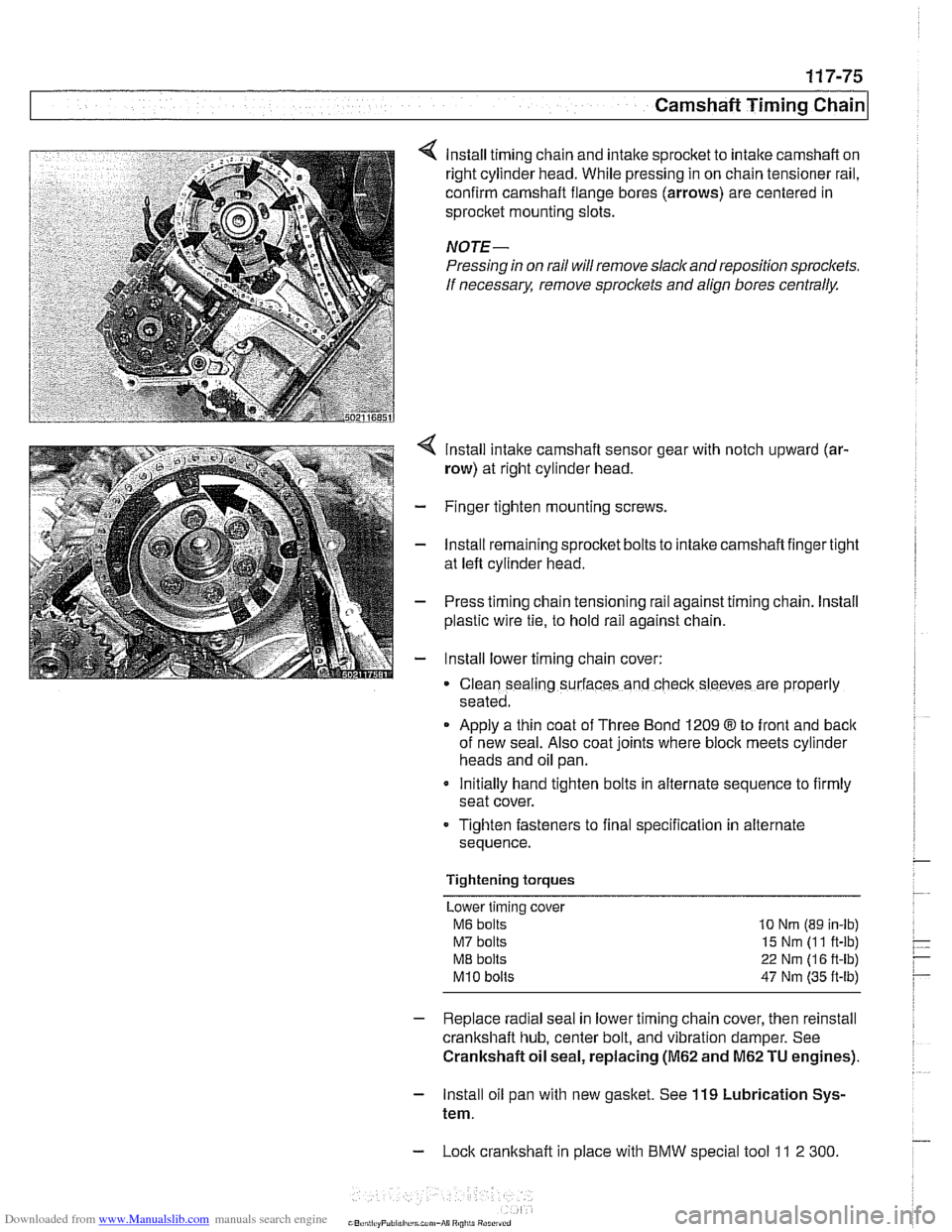
lnstall timing chain and intake sprocket to intake camshaft on
right cylinder head. While pressing in on chain tensioner rail,
confirm camshaft flange bores (arrows) are centered in
sprocket mounting slots.
NOTE-
Pressing in on rail will remove slack and reposition sprockets.
If
necessarx remove sproclets and align bores centrally.
lnstall intake camshaft sensor gear with notch upward (ar-
row) at right cylinder head.
- Finger tighten mounting screws.
- lnstall remaining sprocket bolts to intake camshaft finger tight
at left cylinder head.
- Press timing chain tensioning rail against timing chain. lnstall
plastic wire
tie, to hold rail against chain.
- lnstall lower timing chain cover:
Clean sealing surfaces and check sleeves are properly
seated.
Apply a thin coat of Three Bond 1209
8 to front and back
of new seal. Also coat joints where block meets cylinder
heads and oil pan.
Initially hand tighten bolts in alternate sequence to firmly
seat cover.
Tighten fasteners to final specification in alternate
sequence.
Tightening torques Lower timing cover
M6 bolts 10 Nrn (89 in-lb)
M7 bolts 15 Nm (1 1 ft-lb)
ME bolts 22 Nm (1 6 ft-lb)
M10 bolts 47 Nm (35 ft-lb)
- Replace radial seal in lower timing chain cover, then reinstall
crankshaft hub, center bolt, and vibration damper. See
Crankshaft oil seal, replacing
(M62 and M62 TU engines).
- lnstall oil pan with new gasket. See 119 Lubrication Sys-
tem.
- Lock crankshaft in place with BMW special tool 11 2 300
Page 321 of 1002
Downloaded from www.Manualslib.com manuals search engine
11 9 Lubrication System
General ............................ 11 9-2
Special tools
......................... 11 9-2
..................... Engine lubrication 11 9-3
Troubleshooting .................... 11 9-3
................. Oil pressure. checking 11 9-4
...... Oil pressure warning system. testing 11 9-5
Crankshaft Rear Main Seal ......... .I1 9-6
Crankshaft rear main seal.
replacing (6-cylinder)
.................. 11 9-6
Crankshaft rear main seal. replacing (V-8)
. . 11 9-8
Engine Oil Pan .................... .I1 9-10
Oil pan. removing and
................. installing (6-cylinder) .I1 9-10
Lower oil pan. removing and
installing (V-8)
....................... 1 19-1 3
Upper oil pan. removing and
installing (V-8)
....................... 11 9-1 5
.......... Component Replacement 11 9-20
Oil pressure warning switch. replacing
.................. (6-cylinder and V-8) 11 9-20
Oil level warning switch. replacing
.................. (6-cylinder and V-8) 11 9-21
Oil pump. removing and
................. installing (6-cylinder) 11 9-22
Oil pump. removing and installing (V-8)
. . 11 9-24
..... Oil pressure relief valve (6-cylinder) 119-26
.......... Oil pressure
relief valve (V-8) 11 9-27
Page 326 of 1002
Downloaded from www.Manualslib.com manuals search engine
Lubrication System
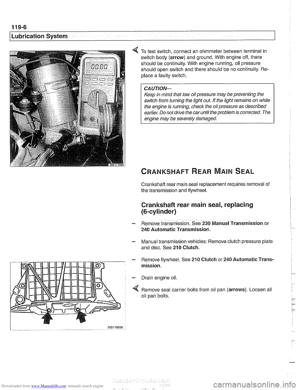
To test switch, connect an ohmmeter between terminal in
switch body (arrow) and ground. With engine off, there
should be continuity. With engine running, oil pressure
should open switch and there should be no continuity. Re-
place a faulty switch.
CAUTION-
Keep in mind that low oil pressure may be preventing the
switch from turning the light out
If the light remains on while
the engine is running, check the oil pressure as described
earlier. Do not drive the car until the problem is corrected. The
engine may be severely damaged.
Crankshaft rear main seal replacement requires removal of
the transmission and flywheel.
Crankshaft rear main seal, replacing
(&cylinder)
- Remove transmission. See 230 Manual Transmission or
240 Automatic Transmission.
- Manual transmission vehicles: Remove clutch pressure plate
and disc. See
210 Clutch.
- Remove flywheel. See 210 Clutch or 240 Automatic Trans-
mission.
- Drain engine oil.
4 Remove seal carrier bolts from oil pan (arrows). Loosen all
oil pan bolts.
Page 328 of 1002
Downloaded from www.Manualslib.com manuals search engine
I Lubrication System -
- Remainder of assembly is reverse of disassembly.
Install flywheel, clutch or torque converter and
transmission.
Fill engine with oil.
- Run engine and check for leaks.
Tightening torques
Oil
drain plug fo oil pan (MI21 25 Nm (18 ft-lb)
Oil pan to engine
block
M6 (8.8 grade) 10 Nm (89 in-ib)
M6 (1 0.9 grade) 12 Nm (9 ft-lb)
M8 (8.8 grade) 22 Nm (1 6 it-lb)
Rear main seal carrier to crankcase
M6 10 Nm (89 in-lb)
ME 22 Nm (16 ft-lb)
Crankshaft rear main seal, replacing (V-8)
- Remove transmission. See 230 Manual Transmission or
240 Automatic Transmission.
- Manual transmission vehicles: Remove clutch pressure plate
and disc. See
210 Clutch.
- Remove flywheel. See 210 Clutch.
- Drain engine oil.
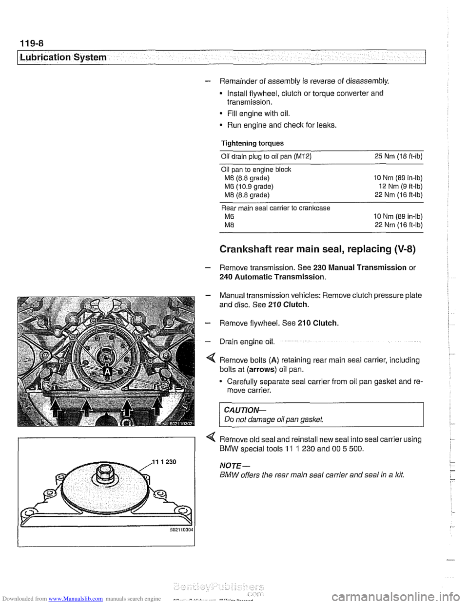
4 Remove bolts (A) retaining rear main seal carrier, including
bolts at (arrows) oil pan.
Carefully separate seal carrier from oil pan gasket and re-
move carrier.
CAUTION-
Do not damage oil pan gasket.
< Remove old seal and reinstall new seal into seal carrier using
) BMW special tools 11 1 230 and 00 5 500.
Page 340 of 1002
Downloaded from www.Manualslib.com manuals search engine
Lubr~cat~on System r- -
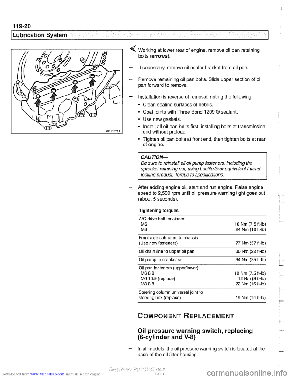
Working at lower rear of engine, remove oil pan retaining
bolts
(arrows).
- If necessary, remove oil cooler bracket from oil pan.
- Remove remaining oil pan bolts. Slide upper section of oil
pan forward to remove.
- Installation is reverse of removal, noting the following:
Clean sealing surfaces of debris.
- Coat joints with Three Bond 1209 O sealant.
Use new gaskets.
Install all oil pan bolts first, installing bolts at transmission
end without preload.
Tighten oil pan bolts at front end, then tighten bolts at rear
of engine.
Be sure to reinstall all oil
pump fasteners, including the
sprocl
speed to
2,500 rpm until oil pressure warning light goes out
(about
5 seconds).
Tightening torques
AIC drive belt tensloner
M6 10 Nm (7.5 it-lb)
M8 24 Nm (18 ft-lb)
Front axle
subframe to chassis
(Use new fasteners) 77 Nm (57 ft-lb)
Oil drain
line to upper oil pan 30 Nm (22 ft-lb)
Oil pump to crankcase 34 Nm (25 ft-lb)
Oil pan fasteners
(upperllower)
M6 8.8 10 Nm (7.5 ft-lb)
M6 10.9 (replace)
I2 Nm (9 ft-lb)
M8 8.8 22 Nm (16 ft-lb)
Steering column universal joint to
steering box (replace) 19 Nm (14 ft-lb)
Oil pressure warning switch, replacing
(&cylinder and V-8)
- In all models, the oil pressure warning switch is located at the
base of the oil filter housing.
Page 341 of 1002
Downloaded from www.Manualslib.com manuals search engine
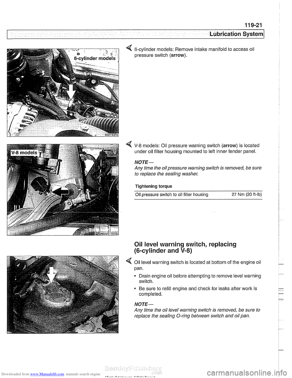
< 6-cylinder models: Remove intake manifold to access oil
pressure switch
(arrow).
V-8 models: Oil pressure warning switch (arrow) is located
under oil filter housing mounted to left inner fender panel.
NOTE-
Any time the oilpressure warning switch is removed, be sure
to replace the sealing washer.
Tightening torque Oil
~ressure switch to oil filter housins 27 Nrn (20 ft-lb)
Oil level warning switch, replacing
(6-cylinder and
V-8)
4 Oil level warning switch is located at bottom of the engine oil
pan.
Drain engine oil before attempting to remove level warning
switch.
Be sure to refill engine and check for leaks after work is
completed.
NOTE-
Any time the oil level warning switch is removed, be sure to
replace the sealing O-ring between switch and oil pan.
Page 349 of 1002
Downloaded from www.Manualslib.com manuals search engine
120 lgnition System
...................... General
Special tools ...................
Warnings and cautions ...........
Engine management .............
................. lgnition system
Ignition system. troubleshooting
....
... Oscilloscope diagnostic diagrams
................ Misfire detection
............. Ignition System Service 120-9
.................... Ignition firing order 120-9
.............. Disabling ignition system 120-10
................... Checking for spark 120-1 0
lgnition coil assembly.
................. testing and replacing 120-1 0
.............. Crankshaftspeedsensor 120-12
............. Camshaft position sensors 120-1 4
...................... Knocksensors 120-16
Page 358 of 1002
Downloaded from www.Manualslib.com manuals search engine
.-
ignition System
Disabling ignition system
The ignition system operates in a lethal voltage range and
should be disabled any time engine service or repair work is
being done that requires the ignition to be switched on.
The engine management system can be disabled by remov-
ing the DME main relay. The relay is located in the electronics
box (E-box) in the left rear of the engine
compartment, be.
neath the interior microfilter housing.
CAUTION- Relay locations may
vary. Use care when identifying relays.
See
610 Electrical Component Locations.
Checking for spark
CAUTION-
If
a spark test is done incorrecth damage to the Engine Con-
trol Module
(ECM) or the ignition coils may result.
NOTE-
Spark plug replacement is covered in 020 Maintenance.
Check~ng for spark is d~fflcult on englnes wlth d~str~butorless
ignition systems.
Try removing the spark plugs and inspecting for differences between them.
A poor-firing plug may be wet with fuel and/or ~. - ~
black and sooty, but not always. If a coil is not operating, the
engine management system will electrically disable the fuel
injector to that cylinder. The key is to look for differences be-
tween cylinders.
Ignition coil assembly, testing and
replacing
C4 UTION-
Use a digital multimeter for the following tests. I
- Remove plastic engine cover from top of valve cover by pry-
ing off bolt covers and removing cover mounting bolts.
- Raise car slowly while constantly checking position of jack
and car.
- Disconnect harness connector from coil. Connect multimeter
between terminal 15
(+) in connector and ground.
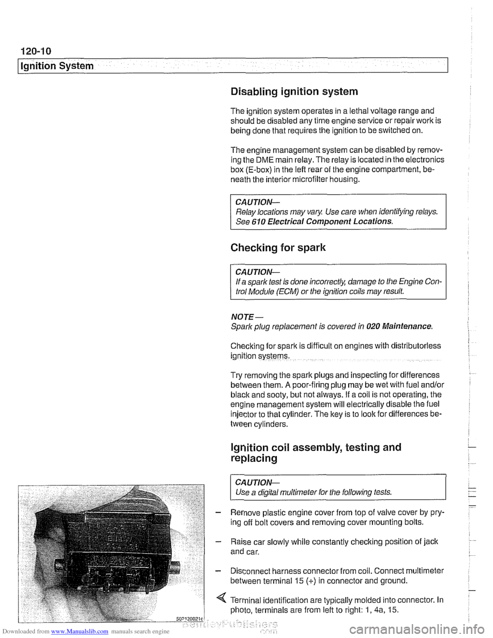
4 Terminal identification are typically molded into connector. In
photo, terminals are from left to right: 1,
4a, 15.