replacing BMW 540i 1997 E39 Repair Manual
[x] Cancel search | Manufacturer: BMW, Model Year: 1997, Model line: 540i, Model: BMW 540i 1997 E39Pages: 1002
Page 458 of 1002
Downloaded from www.Manualslib.com manuals search engine
130-68
Fuel Injection
0
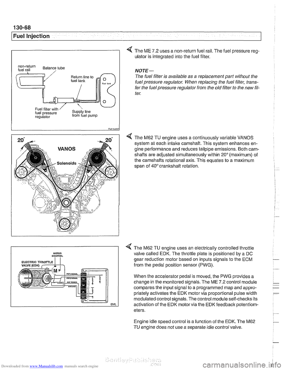
4 The ME 7.2 uses a non-return fuel rail. The fuel pressure reg-
ulator is integrated into the fuel filter.
I iY.,lii,in
4 The M62 TU engine uses a continuously variable VANOS
system at each intake camshaft. This system enhances en-
gine performance and reduces tailpipe emissions. Both cam-
shafts are adjusted simultaneously within
20" (maximum) of
the camshafts rotational axis. This equates to a maximum
span of
40°crankshaft rotation.
regulalor from luel pump
NOTE-
The fuel filter is available as a replacement part without the
fuel pressure regulator. When replacing the fuel filter, trans-
fer the fuel pressure regulator from the old
filter to the new fil-
ter.
Engine idle speed control is a function of the EDK. The M62
TU engine does not use a separate idle control valve.
Mmn CON,ROL
EML
< The M62 TU engine uses an electrically controlled throttle
valve called EDK. The throttle plate is positioned by a DC
gear reduction motor based on inputs signals to the ECM
from the pedal position sensor (PWG).
When the accelerator pedal is moved, the PWG provides a
change in the monitored signals. The ME
7.2 control module
compares the input signal to a programmed map and appro-
priately activates the EDK motor via proportional pulse width
modulated control signals. The control module self-checks its
activation of the EDK motor via the EDK feedbaclc
potentiom-
eters.
Page 461 of 1002
Downloaded from www.Manualslib.com manuals search engine
Fuel Injection I
Engine coolant temperature (ECT) sensor,
testing
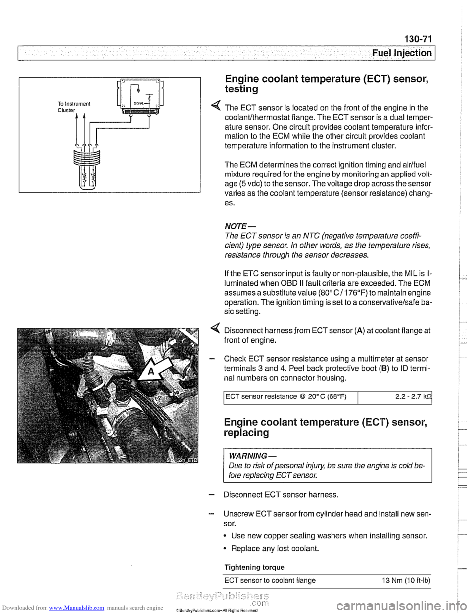
The ECT sensor is located on the front of the engine in the
coolant~thermostat flange. The ECT sensor is a dual temper-
ature sensor. One circuit provides coolant temperature infor-
mation to the ECM while the other circuit provides coolant
temperature information to the instrument cluster.
The ECM determines the correct ignition timing and
airlfuel
mixture required for the engine by monitoring an applied volt-
age
(5 vdc) to the sensor. Thevoltage drop across the sensor
varies as the coolant temperature (sensor resistance) chang-
es.
NOTE-
The ECT sensor is an NTC (negative temperature coeffi-
cient) type sensor. In other words, as the temperature rises,
resistance through the sensor decreases.
If the ETC sensor input is faulty or non-plausible, the MIL is il-
luminated when OBD
II fault criteria are exceeded. The ECM
assumes a substitute value
(80" C/ 176°F) to maintain engine
operation. The ignition timing is set to a
conse~ativelsafe ba-
sic setting.
Disconnect harness from
ECTsensor (A) at coolant flange at
front of engine.
- Check ECT sensor resistance using a multimeter at sensor
terminals
3 and 4. Peel back protective boot (B) to ID termi-
nal numbers on connector housing.
I ECT sensor resistance @ 20" C (68°F) I 2.2 - 2.7 lkCi
Engine coolant temperature (ECT) sensor,
replacing
I WARNING-
/ Due to risk ofpersonal injury, be sure the engine is cold be- I
I fore replacin~~~~sensor. -
-
I
- Disconnect ECT sensor harness.
- Unscrew ECT sensor from cylinder head and install new sen-
sor.
Use new copper sealing washers when installing sensor.
Replace any lost coolant.
Tightening torque
ECT sensor to coolant flange 13 Nm (10 it-lb)
Page 462 of 1002
Downloaded from www.Manualslib.com manuals search engine
130-72
Fuel Injection
I Oxygen sensors, replacing
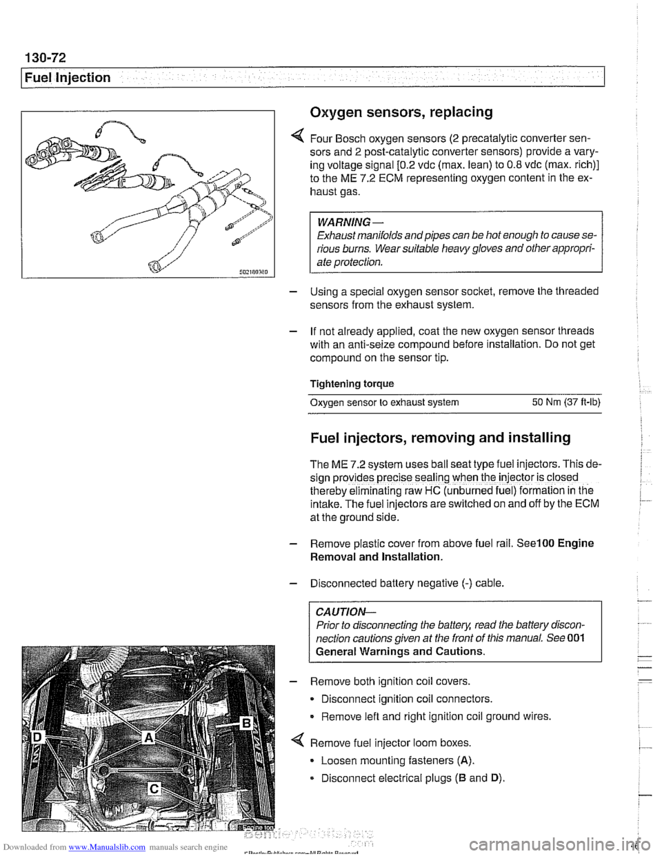
4 Four Bosch oxygen sensors (2 precatalytic converter sen-
sors and
2 post-catalytic converter sensors) provide a vary-
ing voltage signal
[0.2 vdc (max. lean) to 0.8 vdc (max. rich)]
to the ME
7.2 ECM representing oxygen content in the ex-
haust gas.
WARNING-
Exhaust manifolds and pipes can be hot enough to cause se-
rious burns. Wear suitable heavy gloves and other appropri-
ate protection.
- Using a special oxygen sensor socltet, remove the threaded
sensors from the exhaust system.
- If not already applied, coat the new oxygen sensor threads
with an anti-seize compound before installation. Do not get
compound on the sensor tip.
Tightening torque
Oxygen sensor to exhaust system
50 Nm (37 ft-lb)
Fuel injectors, removing and installing
The ME 7.2 system uses ball seat type fuel injectors. This de-
sign
prov:des precise seal'ng when the iniector is closed
therebv eiminalinq raw HC (unb~rned fue ) formalion in tne
intake.-~he fuel inkctors areswitched on and off by the ECM
at the ground side.
- Remove plastic cover from above fuel rail. See100 Engine
Removal and Installation.
- Disconnected battery negative (-) cable.
CAUTION-
Prior to disconnecting the battea read the battery discon-
nection cautions given at the front of this manual. See 001
General Warnings and Cautions.
- Remove both ignition coil covers.
Disconnect ignition coil connectors.
Remove left and right ignition coil ground wires,
4 Remove fuel injector loom boxes.
Loosen mounting fasteners
(A).
Disconnect electrical plugs (B and D).
Page 475 of 1002
Downloaded from www.Manualslib.com manuals search engine
Fuel Tank and Fuel Pump
Warnings and cautions
Observe the following warnings and cautions when servicing
the fuel system.
WARNING-
* The fuel system is designed to retain pressure even when
the ignition is off. When working with the fuelsystem, loos-
en the fuel lines slowly to allow residual
fuel pressure to
dissipate. Avoid spraying fuel. Use shop rags to capture
leaking fuel.
Before beginning any work on the fuel system, place a
fire extinguisher in the vicinity of the work area.
Fuel is highly flammable. When working around fuel, do
not disconnect any wires that could cause electrical
sparks. Do not smoke or worknearheaters or other fire
hazards.
* Always unscrew the fuel tank cap to release pressure
in the
tanlc before working on the tank or lines.
When disconnecting a fuel hose, wrap shop rag around
end of hose to prevent spray of fuel under pressure.
Do not use a work light with an incandescent bulb near
any fuel. Fuel may spray on the hot bulb causing a fire.
0 Make sure the worlc area is properly ventilated.
CAUTION-
- Prior to disconnecting the battery, read the battery discon-
nection cautions given in
001 General Cautions an4
Warnings.
Before
making any electrical tests with the ignition
turned on, disable the ignition system as described in
120 Ignition System. Be sure the battery is discon-
nected when replacing components.
To prevent damage to the ignition system or other DME
components, including the engine control module
(ECM), always connect and disconnect wires and test
equipment with the ignition off.
Cleanliness is essential when
worl~ing with the fuel sys-
tem. Thoroughly clean the fuel line unions before dis-
connecting any of the lines.
Use only clean tools. Keep removed parts clean and
sealed or covered with a clean, lint-free cloth, especial-
ly if completion of the repair is delayed.
Do not move the car while the fuel system is open.
Avoid using high pressure compressed air to blow out
lines and components. High pressure can rupture inter-
nal seals and gaskets.
Always replace seals, O-rings and hose clamps.
Page 479 of 1002
Downloaded from www.Manualslib.com manuals search engine
.- -
Fuel Tank and Fuel purnpl
Fuel pump power consumption, testing
To achieve accurate test results, the battery voltage at the
fuel pump connector should be
12.6 volts. Charge the battery
as necessary.
A higher than normal power consumption may indicate a
worn fuel pump, which may cause intermittent fuel starvation
due to pump overheating and seizure. The only remedy is
pump replacement.
A lower than normal power consumption
may indicate a blockage. Be sure to check that the return line
and the pump pickup are not obstructed before replacing the
pump.
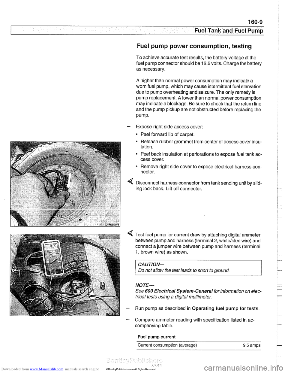
- Expose right side access cover:
Peel forward lip of carpet.
Release rubber grommet from center of access cover insu-
lation.
Peel back insulation at perforations to expose fuel tank ac-
cess cover.
Remove right side cover to expose electrical harness con-
nector.
Disconnect harness connector from tank sending unit by slid-
ing lock back. Lift off connector.
Test fuel pump for current draw by attaching digital ammeter
between pump and harness (terminal
2, whitelblue wire) and
connect a jumper wire between pump and harness (terminal
1, brown wire) as shown.
CAUTION-
Do not allow the test leads to short to ground.
NOTE-
See 600 Electrical Systern-General for information on elec-
trical tests
using a digital multirneter.
Run pump as described in Operating fuel pump for tests.
- Compare ammeter reading with specification listed in ac-
companying table.
Fuel
pump current
Current consumption (average) 9.5 amps
Page 485 of 1002
Downloaded from www.Manualslib.com manuals search engine
.-
err- .- Fuel Tank and Fuel Pump
FUELPUMP AND FUELLEVELSENDER
E39 models use a two-lobed fuel tank. Each lobe of the tank
has its own fuel level sending unit. Each sender has a float
connected to a variable resistance wipercontact. To equalize
fuel level between the two
tank lobes, a siphon pump is in-
stalled in the left lobe.
When replacing asender or fuel pump, always replace hose
clamps,
gasltets and O-rings.
WARNING
-
When removing the fuel level sender or the fuel pump, the
fuel tank should be drained to
1/4 capacity or below as de-
scribed later in this repair group.
NOTE-
The compensating siphon pump maintains the fuel level be-
tween the right and left tank lobes. If fuel level sender resis-
tances are not approximately the same on left and right,
remove the senders and visually inspect the level in each
lobe. If the levels are different, check the siphon pump.
Fuel level sender resistances
Float position
l~est results (Q
Down (empty) 150- 70
Up (full) 1401 -415
Fuel level sender (right side) and fuel
pump, removing
and installing
- Drain fuel from tank as described later.
- Disconnect negative cable from battery.
CAUTION-
Prior to disconnecting the battery, read the battery discon-
nection cautions given in
001 General Cautions and
Warnings.
- To access top of fuel tank, remove rear seat lower cushion by
lifting front edge
off catches.
Page 487 of 1002
Downloaded from www.Manualslib.com manuals search engine
.- .
Fuel Tank and Fuel Pump
- To reinstall:
Use new sealing ring at tank collar.
* Align tab of sending unit with matching recess in opening
of tank.
Be sure that fuel line connections point in same direction
as they came out.
Reconnect harness connector and hose.
Fill tank and check for leaks by running engine.
Install access cover and its mounting fasteners.
CAUTIOI\C
After finishing repairs but before starting engine, be sure
there is at least
5 liters (1.5 gallons) of fuel in the tank. The
NOTE-
It is common practice to replace the fuel filter when the fuel
pump
unit is replaced. See 020 Maintenance.
Tightening torque
Tank collar locking ring to tank 35 Nm (26 lb-ft)
Fuel level sender (left side),
removing and installing
The procedure for removing and replacing the left side fuel
level sender is
simllar to that used for the r~ght side. There is
no fuel pump on the left side.
- Remove rear seat lower cushion by lifting off catches at front.
- Expose left side access cover:
- Peel forward lip of carpet.
Release rubber grommet from center of access cover
insulation.
Peel back insulation at
perforations to expose fuel tank
access cover.
Remove cover to expose electrical harness connector.
WARNING-
Fuel may be spilled. Do not smoke or work near heaters or
other fire hazards.
When disconnecting fuel hose, wrap shop rag around
end of hose to prevent spray of fuel under pressure.
Page 497 of 1002
Downloaded from www.Manualslib.com manuals search engine
176 Radiator and Cooling System
General ........................... .I7 0.2
Special tools
........................ .I7 0.2
Cooling system overview
(M52 TU shown. others similar) ......... .I7 0.3
Coolant pump
....................... .I7 0.3
Thermostat
......................... .I7 0.3
Mechanical thermostat (M52 engine)
..... .I7 0.4
Electrically heated thermostat
.......... .I7 0.4
Radiator and expansion tank
........... .I7 0.4
Mechanical cooling fan with viscous clutch
.I7 0.4
Electric (auxiliary) cooling fan ........... .I7 0.4
Transmission fluid heat exchanger
....... .I7 0.5
Warnings and cautions
................ .I7 0.7
Troubleshooting ................... .I7 0.7
Cooling system inspection
............. .I7 0.8
Cooling system pressure test
........... .I7 0.9
Combustion chamber leak test
......... .I7 0.10
Thermostat
........................ .I7 0.1 0
Cooling System Service ........... 170-10
Coolant. draining and filling
(6-cylinder models)
.................. 170-1 0
Coolant. draining and filling (V-8 models)
. 170-12
Cooling system. bleeding
............. 170-14
Mechanical (viscous clutch) cooling fan.
removing and installing
............... 170-14
Electric cooling fan.
removing and installing
............... 170-15
Thermostat. removing and installing
(M52engine) ....................... 170-16
Thermostat. removing and installing
(M52 TU or M54 engine) .............. 170-17
Thermostat. removing and installing (V-8 models)
....................... 170-1 8
Coolant pump. replacing (6-cylinder models)
.................. 170-1 9
Coolant pump. replacing (V-8 models) ... 170-20
Radiator. removing and installing
....... 170-22
Expansion tank. removing and
installing . . 170-24
Page 507 of 1002
Downloaded from www.Manualslib.com manuals search engine
170-1 1
Radiator and Cooling system/
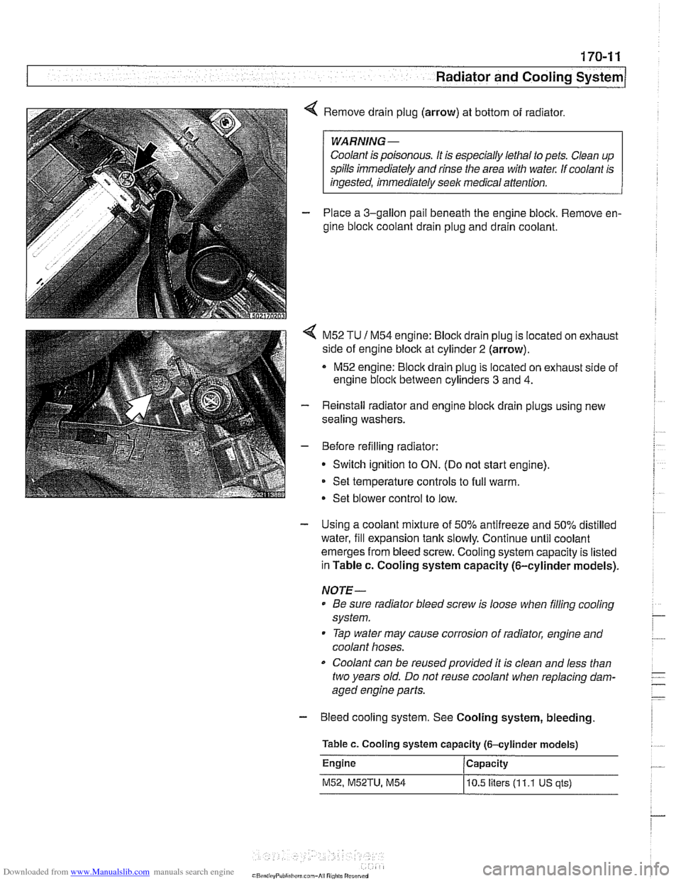
4 Remove drain plug (arrow) at bottom of radiator.
Coolant is poisonous. It is especially lethal to pets. Clean up
spills immediately and rinse the area with
wate,: If coolant is
- Place a 3-gallon pail beneath the engine block. Remove en-
gine block coolant drain plug and drain coolant.
< M52 TU 1 M54 engine: Bloclc drain plug is located on exhaust
side of engine block at cylinder
2 (arrow).
M52 engine:
Bloclc drain plug is located on exhaust side of
engine
bloclc between cylinders 3 and 4.
- Reinstall radiator and engine block drain plugs using new
sealing washers.
- Before refilling radiator:
Switch ignition to
ON. (Do not start engine).
Set temperature controls to full warm.
Set blower control to low.
- Using a coolant mixture of 50% antifreeze and 50% distilled
water, fill expansion tank slowly. Continue until coolant
emerges from bleed screw. Cooling system capacity is listed
in Table c. Cooling system capacity (6-cylinder models).
NOTE-
Be sure radiator bleed screw is loose when filling cooling
system.
Tap water may cause corrosion of radiator, engine and
coolant hoses.
Coolant can be reusedprovided it is clean and less than
two years old. Do not reuse coolant when replacing dam-
aged engine parts.
- Bleed cooling system. See Cooling system, bleeding
Table c. Cooling system capacity (6-cylinder models)
Engine Capacity
M52, M52TU, M54
10.5 liters (1 1.1 US qls)
Page 509 of 1002
Downloaded from www.Manualslib.com manuals search engine
170-1 3
Radiator and Cooling ~vsteml
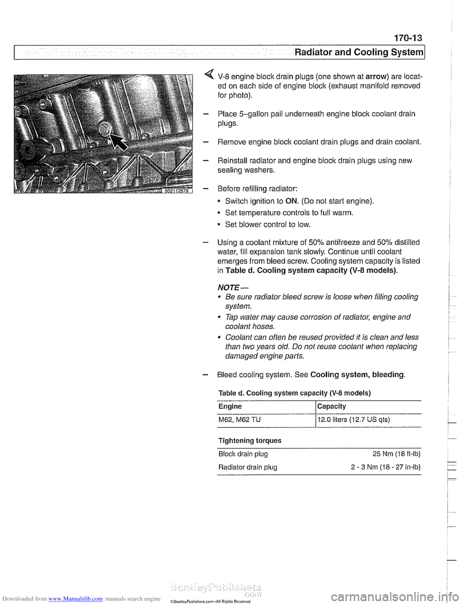
< V-8 engine bloclc drain plugs (one shown at arrow) are locat-
ed on each side of engine block (exhaust manifold removed
for photo).
- Place 5-gallon pail underneath engine block coolant drain
plugs.
- Remove engine bloclc coolant drain plugs and drain coolant.
- Reinstall radiator and engine block drain plugs using new
sealing washers.
- Before refilling radiator:
Switch ignition to
ON. (Do not start engine)
Set temperature controls to full warm.
- Set blower control to low.
- Using a coolant mixture of 50% antifreeze and 50% distilled
water, fill expansion tank slowly. Continue until coolant
emerges from bleed screw. Cooling system capacity is listed
in Tabled. Cooling system capacity
(V-8 models).
NOTE- Be sure radiator bleed screw is loose when filling cooling
system.
Tap water may cause corrosion of radiator, engine and
coolant hoses.
Coolant can often be reused provided it is clean and less
than two years old. Do not reuse coolant when replacing
damaged engine parts.
- Bleed cooling system. See Cooling system, bleeding
Tabled. Cooling system
capacity (V-8 models)
M62, M62 TU 12.0 liters (12.7 US qts)
Tightening torques
Block drain plug
25 Nm (18 ft-lb)
Radiator drain plug
2 - 3 Nm (18 - 27 in-lb)