replacing BMW 540i 1997 E39 Owner's Guide
[x] Cancel search | Manufacturer: BMW, Model Year: 1997, Model line: 540i, Model: BMW 540i 1997 E39Pages: 1002
Page 359 of 1002
Downloaded from www.Manualslib.com manuals search engine
Ignition System
- Turn ignition on and check for battery voltage,
If battery voltage is not present,
checlt wire between termi-
nal
15 and the unloader relay. See ELE Electrical Wiring
Diagrams.
- Turn ignition off.
Remove coil and inspect coil housing for hairline
cracks or
leaking casting material. Replace any
cracked or leaking coil.
NOTE-
A leaky coil may indicate a faulty Engine Control Module
(ECM). Check ECM before installing a new coil.
CAUTION-
Note location of coilground straps before coil removal; rein-
stall in the same location.
Use a multimeter to test:
Coil primary resistance at coil terminals.
Sparlt plug connector resistance.
* Compare results to specification in Table c. lgnition coil
resistance.
Table c. Ignition coil resistance
Coil secondary
resistance
Spark plug connector:
Bosch 1 .O I( ohm t 20%
1.8 ir ohm t 20%
Component
Co~l prlmary
resistance
- Replace ignition coil or sparlt plug connector if resistance
readings do not meet specifications.
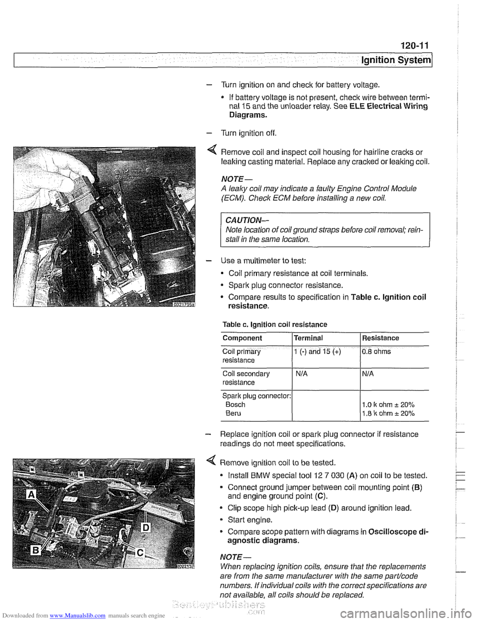
4 Remove ignition coil to be tested.
Install
BMW special tool 12 7 030 (A) on coil to be tested.
Connect ground jumper between coil mounting point
(B)
and engine ground point (C).
Clip scope high pick-up lead (D) around ignition lead.
Start engine.
Compare scope pattern with diagrams in Oscilloscope
di-
agnostic diagrams.
NOTE-
When replacing ignition coils, ensure that the replacements
Terminal
1 (-) and 15 (+)
are
from the same manufacturer with the same partlcode
numbers. If individual coils with the correct specifications are
not available. all coils should be
re~laced.
Resistance
0.8 ohms
Page 360 of 1002
Downloaded from www.Manualslib.com manuals search engine
120-1 2
ignition System
Crankshaftspeedsensor
Crankshaft speed sensor, replacing (M52, M52 TU and
M54 engines)
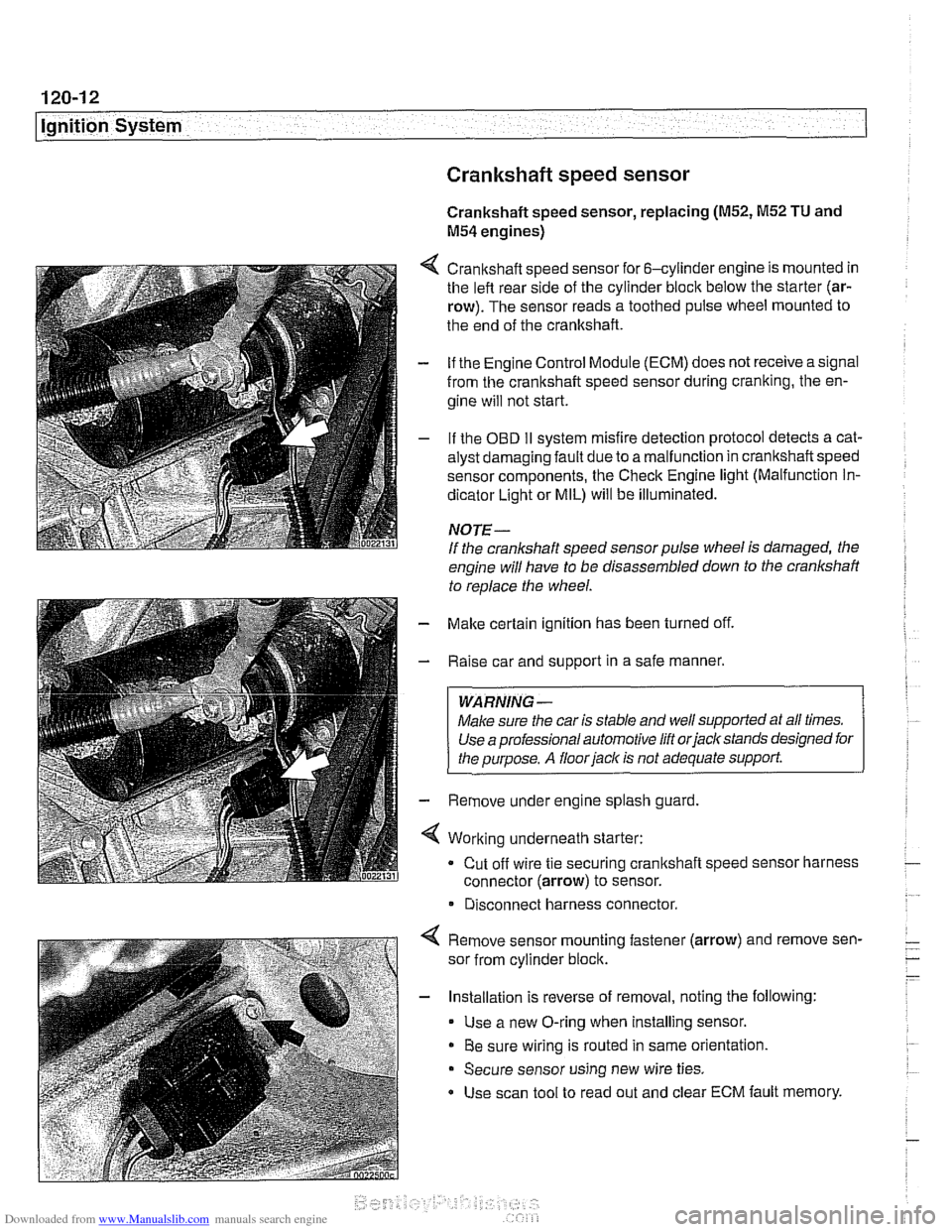
4 Crankshaft speed sensor for 6-cylinder engine is mounted in
the left rear side of the cylinder block below the starter (ar-
row). The sensor reads a toothed pulse wheel mounted to
the end of the crankshaft.
- if the Engine Control Module (ECM) does not receive a signal
from the crankshaft speed sensor during cranking, the en-
gine will not start.
- If the OBD II svstem misfire detection ~rotocol detects a cat- - - ~~
alysr oarnagin; faLlt oJe to a ma I-nclion in crandshafi speeo
sensor components. Ine Check Engine
lignr (Malfuncrion In-
dicator Light or MIL) will be illuminated.
NOTE-
If the crankshaft speed sensor pulse wheel is damaged, the
engine will have to be disassembled down to the crankshaft
to
reolace the wheel.
- Make certain ignition has been turned off.
- Raise car and support in a safe manner.
WARNING -
Make sure the car is stable and well supported at all times.
Use a professional automotive lift orjacltstands designed for
the ouroose.
A floor iaclc is not adequate support.
- Remove under engine splash guard
4 Working underneath starter:
Cut off wire tie securing crankshaft speed sensor harness
connector (arrow) to sensor.
* Disconnect harness connector.
4 Remove sensor mounting fastener (arrow) and remove sen-
sor from cylinder block.
- Installation is reverse of removal, noting the following:
Use a new O-ring when installing sensor.
Be sure wiring is routed in same orientation.
Secure sensor using new wire ties.
Use scan tool to read out and clear ECM fault memory.
Page 361 of 1002
Downloaded from www.Manualslib.com manuals search engine
ignition System
Crankshaft speed sensor, replacing (M62 and M62TU
engines)
The crankshaft speed sensor reads a toothed pulse wheel
mounted on the flywheel.
If the Engine Control Module(ECM)
does not receive an impulse signal from the crankshaft speed
sensor during
cranking, the engine will not start. If the OBD II
system misfire detection protocol detects a catalyst damag-
ing fault due to a malfunction in the crankshaft speed sensor
components, the Check Engine light (Malfunction
Indicator
Light or MIL) will be Illuminated.
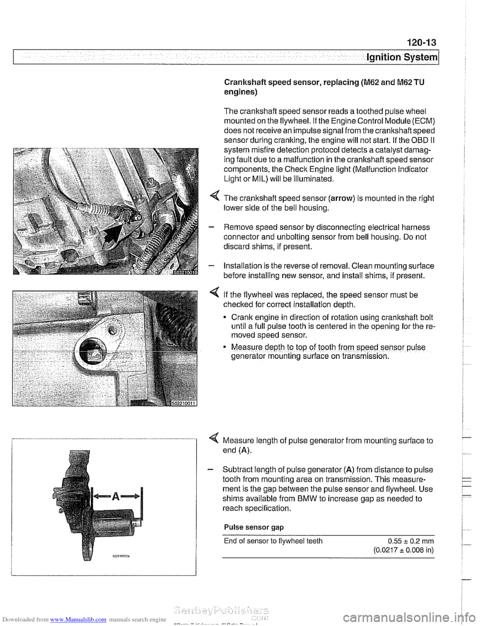
4 The crankshaft speed sensor (arrow) is mounted in the right
lower side of the bell housing.
- Remove speed sensor by disconnecting electrical harness
connector and unbolting sensor from bell housing. Do not
discard shims, if present.
- Installation is the reverse of removal. Clean mounting surface
before installing new sensor, and install shims, if present.
< If the flywheel was replaced, the speed sensor must be
checked for correct installation depth.
* Crank engine in direction of rotation using crankshaft bolt
until a full pulse tooth is centered in the opening for the re-
moved speed sensor.
Measure depth ro top of tooth from speed sensor p~lse
generator mounting s~rface on transmission.
4 Measure length of pulse generator from mounting surface to
end (A).
- Subtract length of pulse generator (A) from distance to pulse
tooth from mounting area on transmission. This measure-
ment is the gap between the pulse sensor and flywheel. Use
shims available from BMW to increase gap as needed to
reach specification.
Pulse sensor
gap
End of sensor to flywheel teeth 0.55 + 0.2 rnrn
(0.0217 t 0.008 in)
Page 362 of 1002
Downloaded from www.Manualslib.com manuals search engine
I Ignition System
Camshaft position sensors
The camshaft position sensors are used by the englne man-
agement system for VANOS control, sequential fuel injection
and knock control.
Intake camshaft position sensor, replacing
(M52,M52 TU
and M54 engines)
- Make certain ignition has been turned off.
- Remove plastic cover from above fuel injectors by prying off
bolt covers and removing cover mounting bolts.
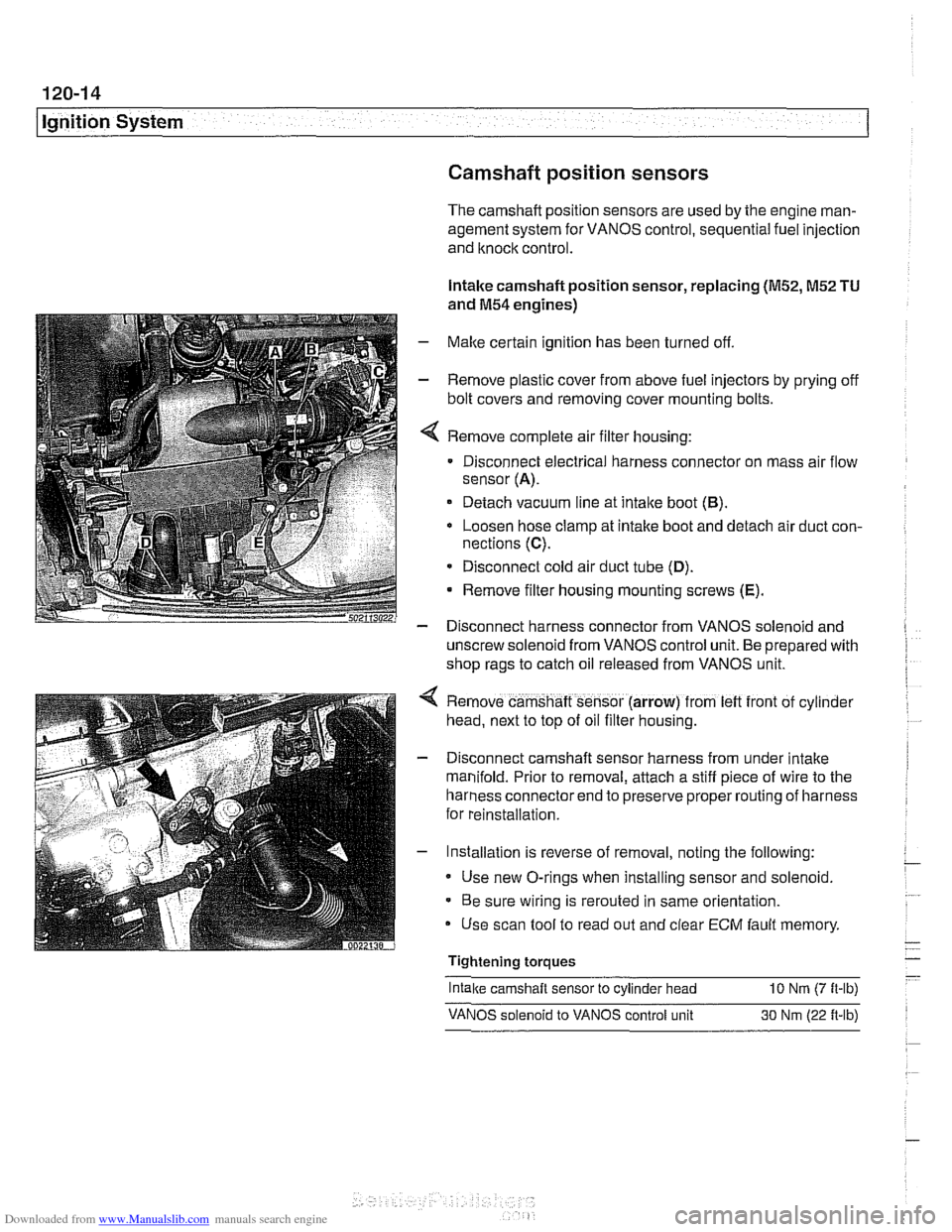
Remove complete air filter housing:
Disconnect electrical harness connector on mass air flow
sensor
(A).
Detach vacuum line at intake boot (B).
Loosen hose clamp at intake boot and detach air duct con-
nections
(C).
* Disconnect cold air duct tube (D).
Remove filter housing mounting screws (E).
- Disconnect harness connector from VANOS solenoid and
unscrew solenoid from VANOS control unit. Be prepared with
shop rags to catch oil released from VANOS unit.
Remove camshaft sensor (arrow) from
left front of cyl~nder
head, next to top of oil filter housing.
Disconnect camshaft sensor harness from under intake
manifold. Prior to removal, attach a stiff piece of wire to the
harness connector end to preserve proper routing of harness
for reinstallation.
Installation is reverse of removal, noting the following:
Use new O-rings when installing sensor and solenoid.
Be sure wiring is rerouted in same orientation.
Use scan tool to read out and clear
ECM fault memory
Tightening torques
-
Intake camshaft sensor to cylinder head 10 Nrn (7 ft-lb)
VANOS solenoid to VANOS control unit 30 Nm (22 ft-lb)
Page 363 of 1002
Downloaded from www.Manualslib.com manuals search engine
120-15
Ignition system1
Exhaust camshaft position sensor, replacing
(M52 TU and M54 engines)
- Make sure ignition has been turned off.
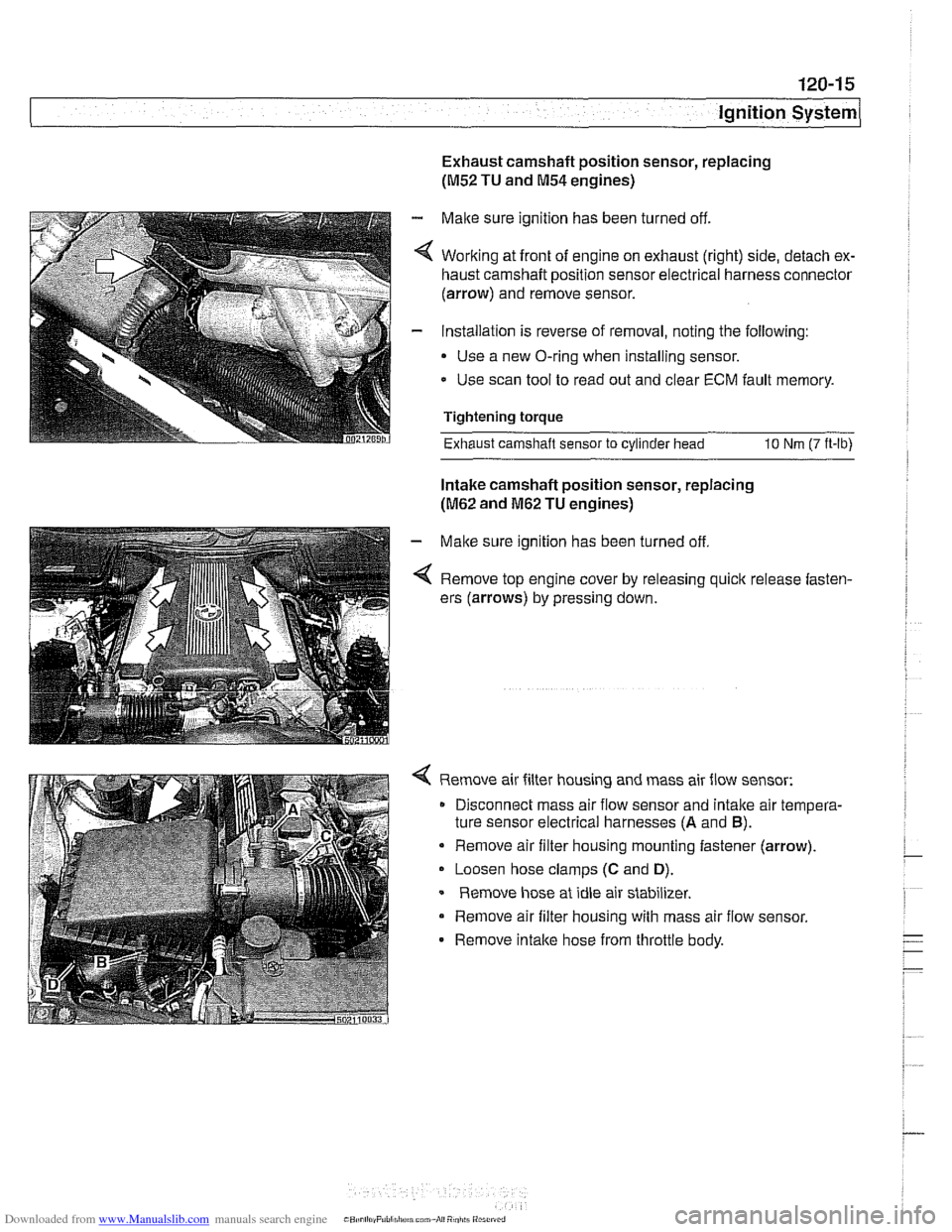
4 Working at front of engine on exhaust (right) side, detach ex-
haust camshaft position sensor electrical harness connector
(arrow) and remove sensor.
- Installation is reverse of removal, noting the following:
Use a new O-ring when installing sensor.
- Use scan tool to read out and clear ECM fault memory.
Tightening torque
Exhaust camshaft sensor
to cylinder head 10 Nm (7 ft-lb)
Intake camshaft position sensor, replacing
(M62 and M62 TU engines)
- Make sure ignition has been turned off
4 Remove top engine cover by releasing quick release fasten-
ers (arrows) by pressing down.
4 Remove air filter housing and mass air flow sensor:
Disconnect mass air flow sensor and
intalte air tempera-
ture sensor electrical harnesses
(A and B).
Remove air filter housing mounting fastener (arrow).
Loosen hose clamps
(C and D).
Remove hose at idle air stabilizer.
Remove air filter housing with mass air flow sensor.
- Remove intalte hose from throttle body.
Page 364 of 1002
Downloaded from www.Manualslib.com manuals search engine
120-1 6
Ignition System
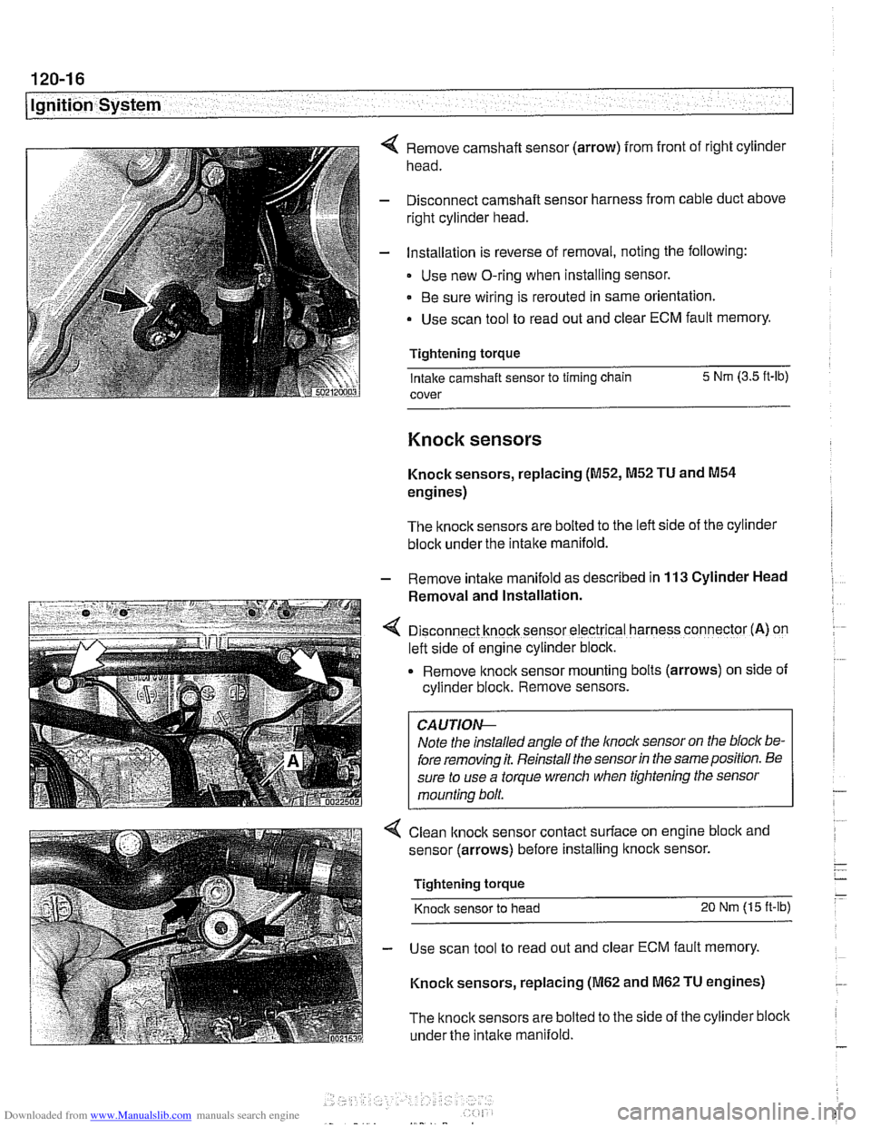
Remove camshaft sensor (arrow) from front of right cylinder
head.
Disconnect camshaft sensor harness from cable duct above
right cylinder head.
Installation is reverse of removal, noting the following:
Use new O-ring when installing sensor.
Be sure wiring is rerouted in same orientation.
Use scan tool to read out and clear ECM fault memory.
Tightening torque Intake camshaft sensor to timing chain 5 Nm
(3.5 ft-lb)
cover
Knock sensors
Knock sensors, replacing (M52, M52 TU and M54
engines)
The knock sensors are bolted to the left side of the cylinder
block under the intake manifold.
- Remove intalte manifold as described in 113 Cylinder Head
Removal and Installation.
D~sconnect knock sensor electrical harness connector (A) on
left side of engine cylinder block.
Remove knock sensor
mount~ng bolts (arrows) on side of
cyllnder block. Remove sensors.
Note the installed angle of the
lnocl~ sensor on the bloc/( be-
fore removing it. Reinstall the sensor
in the same position. Be
sure to use a torque wrench when tightening the sensor
mounting bolt.
< Clean lknock sensor contact surface on engine bloclc and
sensor (arrows) before installing
ltnock sensor.
Tightening torque
Knock sensor to head 20 Nm (15 ft-lb)
- Use scan tool to read out and clear ECM fault memory.
Knock sensors, replacing
(M62 and M62 TU engines)
The
knock sensors are bolted to the side of the cylinder block
under the
intake manifold.
Page 367 of 1002
Downloaded from www.Manualslib.com manuals search engine
121-1
121 Battery. Starter. Alternator
General ........................... .I2 1.2
Special tools ........................ .I2 1.2
Engine electrical system ............... .I2 1.2
Battery Safety Terminal ............... .I2 1.3
Warnings and cautions ................. 121 -4
Battery ............................ 121-5
Battery testing ...................... .I2 1.5
Hydrometer testing ................... .I2 1.5
Battery open-circuit voltage test ......... .I2 1.6
Battery load voltage test ................ 121 -6
Closed-circuit current measurement ..... .I2 1.7
Battery charging ...................... 121 -9
Battery safety terminal, replacing ......... 121-9
Alternator (generator) ............. .I2 1.10
Alternator. basic .................... .I2 1.11
Alternator with multi-function
control (MFR)
...................... .I2 1.11
Water-cooled alternator ............... 121 -12
Charging System Troubleshooting . 121-12
Charging system quick-check .......... 121-13
Charging system. checking ............ 121-13
Alternator. removing and installing
(6-cylinder engine)
.................. 121 -1 5
Alternator. removing and installing
(M62 engine. air cooled)
.............. 121-16
Alternator. removing and installing
(M62 TU engine. water cooled) ......... 121-1 8
Starter ........................... 121 -1 9
Starter troubleshooting ............... 121 -1 9
Starter. removing and installing
(6-cylinder engine)
.................. 121-20
Starter. removing and installing
(V-8 engine)
........................ 121 -21
Solenoid switch. removing and installing . . 121-23
Page 375 of 1002
Downloaded from www.Manualslib.com manuals search engine
121-9
Battery, Starter, ~lternatorl
Battery charging
Discharged batteries can be recharged using a batterycharg-
er. Remove the battery from the trunk during charging.
Prolonged charging causes electrolyte evaporation to a level
that can damage the battery. It is best to use a low-current
charger
(6 amperes or less) to prevent battery damage
caused by overheating.
WARNING -
Hydrogen gas given off by the battery during charging is ex-
plosive. Do not smoke.
Keep open flames away from the top
ofthe batte~ and prevent electrical sparks by turning off the
battery charger before connecting or disconnecting it.
Battery electrolyte (sulfuric acid) can damage the car. If
electrolyte is spilled, clean the area with a solution
ofbak-
ing soda and water.
Always allow a frozen battery to thaw before attempting
to recharge it.
Always disconnect both battery cables and remove bat-
tery from vehicle during battery charging. Do not ex-
ceed
16.5 charging voltage at the battery
Battery safety terminal, replacing
If the battery safety terminal has been triggered, investigate
and correct the cause prior to replacement.
- Working in right side of luggage compartment, remove bat-
tery trim panel.
- Disconnect negative (-) battery terminal and cover with
insulator.
- Disconnect positive (+) cable from battery.
- Release positive (+) cable from cable brackets on luggage
compartment wall. Lay new repair cable parallel to positive
cable.
- Mark off length of new cable on old cable. Allow 10 cm
(2.5 in) of slack.
- Saw through old cable.
Do not use bolt cutters or similar tools to cut through cable.
A cable end that has been squashed
flat will not fit into the
Page 378 of 1002
Downloaded from www.Manualslib.com manuals search engine
Battery, Starter, Alternator
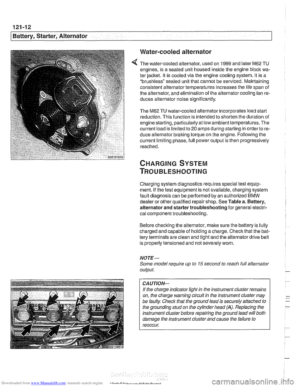
Water-cooled alternator
The water-cooled alternator, used on 1999 and later M62 TU
engines, is a sealed unit housed inside the engine block wa-
ter jacket. It is cooled via the engine cooling system. It is a
"brushless" sealed unit that cannot be serviced. Maintaining
consistent alternator temperatures increases the life span of
the alternator, and elimination of the alternator cooling fan re-
duces alternator noise
significantly.
The M62 TU water-cooled alternator incorporates load start
reduction. This function is intended to shorten the duration of
engine starting, particularly at low ambienttemperatures. The
current load is limited to
20 amps during starting in order to re-
duce alternator braking torque on the engine. Following the
current limiting phase, full power output is then progressively
reached.
Charging system diagnostics requires special test equip-
ment. If the test equipment is not available, charging system
fault diagnosis can be performed by an authorized
BMW
dealer or other qualified repair shop. See Table a. Battery,
alternator and starter troubleshooting for general electri-
cal component troubleshooting.
Before checking the alternator, make sure the battery is fully
charged and capable of holding a charge. Check that the bat-
tery terminals are clean and tight and the alternator drive belt
is properly tensioned and not severely worn.
NOTE-
Some model require up to 15 second to reacli full alternator
output.
CA UTIOG
If the charge indicator light in the instrument cluster remains
on, the charge warning circuit in the instrument cluster may
be faulty. Check that the ground lead is securely
affached to
the grounding stud on the cylinder head
(A). Replacing the
instrument cluster before repairing the ground lead will both
damage the instrument cluster and cause the failure to
reoccur.
Page 391 of 1002
Downloaded from www.Manualslib.com manuals search engine
130-1
130 Fuel injection
General ........................... .I3 0.2
Tools and test equipment .............. .I3 0.3
Warnings and cautions ................ .I3 0.5
Fuel Supply ....................... .I3 0.6
Relieving system fuel pressure .......... .I3 0.6
Siemens MS 41 . 1. ................... 1 30-7
ECM relay. testing .................... .I3 0.7
Mass air flow (MAF) sensor.
checking and replacing
................ .I3 0.9
Engine coolant temperature (ECT) sensor.
testing and replacing
.................. 130-10
Intake air temperature (IAT) sensor.
testing and replacing
................. .I3 0.1 1
Throttle position sensor (TPS).
testing and replacing
.................. 130-1 2
ldle speed control valve.
checking and replacing
............... .I3 0.1 3
Fuel injectors. checking and replacing .... 130-15
Evaporative emissions. overview ....... .I3 0.1 6
Secondary air injection. overview ....... .I3 0-17
Engine control module (ECM).
removing and installing
................ 130-18
Siemens MS 41.1 ECM pin assignments . .I3 0.19
Siemens MS 42.0 and MS 43.0. ..... .I3 0.23
ECM relay. testing ................... .I3 0.27
Mass air flow (MAF) sensor.
checking and replacing
............... .I3 0.28
Engine coolant temperature (ECT) sensor.
testing and replacing
................. .I3 0.30
Intake air temperature (IAT) sensor.
testing and replacing
................. .I3 0.31
MS 42.0 throttle valve assembly. replacing . 130-32
MS 43.0 throttle valve assembly. replacing . 130-35
Throttle cable. adjusting (MS 42.0) ...... .I3 0.38
ldle speed control valve. checking
and replacing
....................... .I3 0.38
Evaporative emissions control diagrams . . 130- 39
Evaporative emissions control.
(MS
42.0 and MS 43.0). .............. .I3 0.39
Engine control module (ECM).
removing and installing
................ 130-40
Siemens MS 42.0 and MS 43.0
ECM pin assignments ................. 130-41
Bosch M5.2 (M62 up to 911997)
BOSC~ M5.2.1 (M62 911997 to 911998) 130-46
M5.2 system features ................. 130-47
M5.2.1 system features ............... 130-47
ECM relay. testing ................... 130-49
Oxygen sensors. checking ............. 130-51
Fuel injectors. checking and replacing .... 130-52
Mass air flow (MAF) sensor. replacing .... 130-53
ldle speed control valve. testing
and replacing
....................... 130-54
Throttle position sensor (TPS).
testing and replacing
................. 130-55
Engine coolant temperature (ECT) sensor.
testing and replacing
................. 130-55
Intake air temperature (IAT) sensor.
testing and replacing
................. 130-57
Auxiliary throttle valve (ADS) (M62 and
M62 TU engine). replacing ..... 130-57
Evaporative system pressure
leak diagnosis. overview
(5.2.1 only) ..... 130-58
Bosch 5.2 ECM pin assignments
(M62 UP to 911 997) ................... 130-59
~osch 5.2.1 ECM pin assignments
(M62 911 997 to 911 998) ............... 130-62
BOSC~ ME 7.2 ..................... 1 30-66
ME 7.2 system overview ............... 130-67
EDK adaptation ..................... 130-69
ECM relay. checking .................. 130-69
Engine coolant temperature
(ECT) sensor. testing
................. 130-71
Engine coolant temperature
(ECT) sensor. replacing
............... 130-71
Oxygen sensors. replacing ............. 130-72
Fuel injectors. removing and installing .... 130-72
Mass air flow (MAF) sensor.
removing and installing
................ 130-73
Evaporative system pressure
leak diagnosis. overview
............... 130-74
Secondary air injection. overview ........ 130-75
Bosch ME 7.2 ECM pin assignments .... 130-76