replacing BMW 540i 1997 E39 Repair Manual
[x] Cancel search | Manufacturer: BMW, Model Year: 1997, Model line: 540i, Model: BMW 540i 1997 E39Pages: 1002
Page 421 of 1002
Downloaded from www.Manualslib.com manuals search engine
Fuel Injection
- Installation is reverse of removal:
Use new copper sealing washers when installing sensor.
Replace any lost coolant.
Tightening torque
Temperature sensor to cylinder head
13 Nm (10 ft-lb)
Intake air temperature (IAT) sensor,
testing and replacing
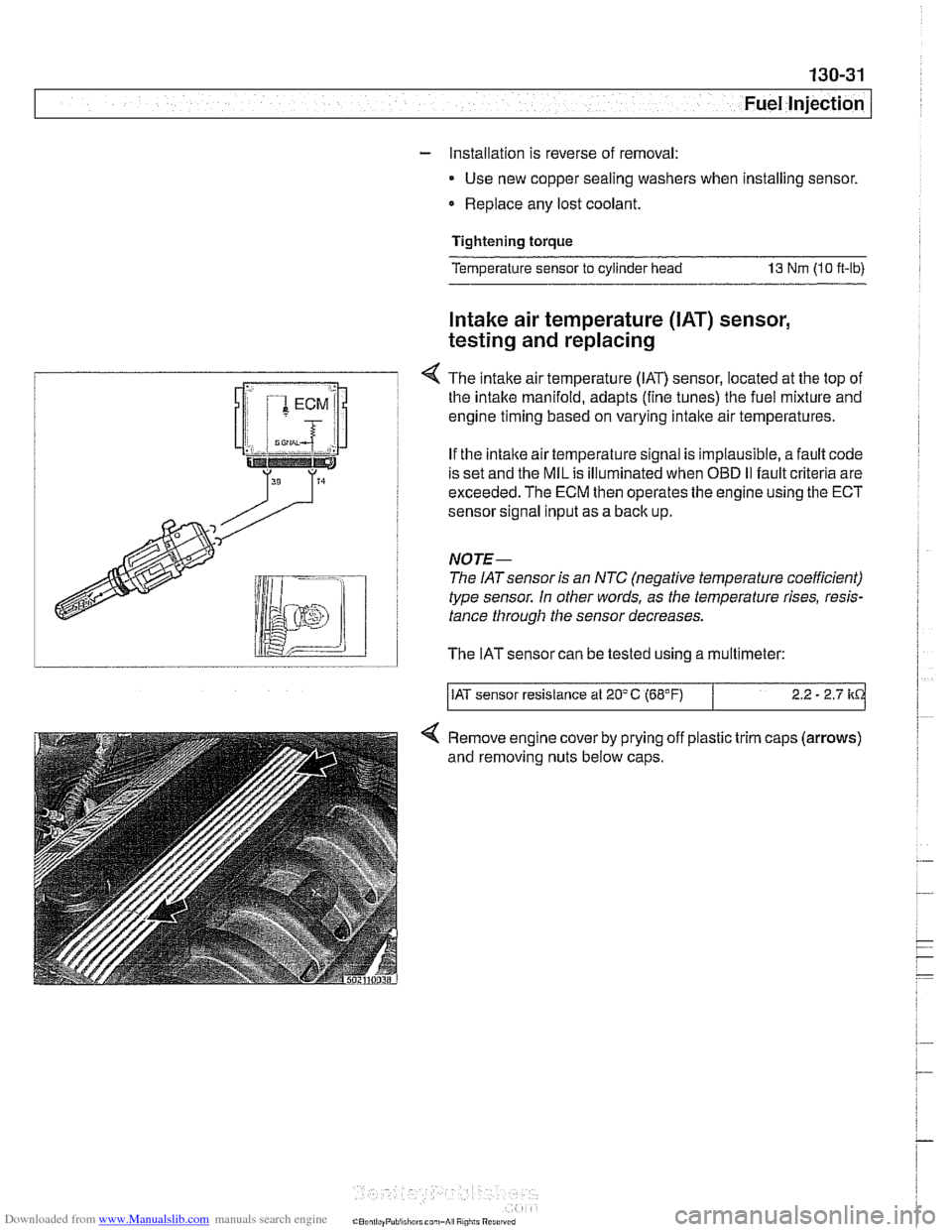
4 The intake airtemperature (IAT) sensor, located at the top of
I the intake manifold, adapts (fine tunes) the fuel mixture and i
T engine timing based on varying intake air temperatures.
i If the intaite air temperature signal is implausible, a fault code
! is set and the MIL is illuminated when OBD I1 fault criteria are
I exceeded. The ECM then operates the engine using the ECT
i sensor sional inout as a back uo.
type sensor. In other words,
a> the temperature rises, resis-
tance through the sensor decreases.
lid I The IATsensor can be tested using a multimeter:
/IAT sensor resistance at 20'C (68°F) 2.2 - 2.7 kd
Remove engine cover by prying off plastic trim caps (arrows)
and removing nuts below caps.
Page 422 of 1002
Downloaded from www.Manualslib.com manuals search engine
Fuel Injection
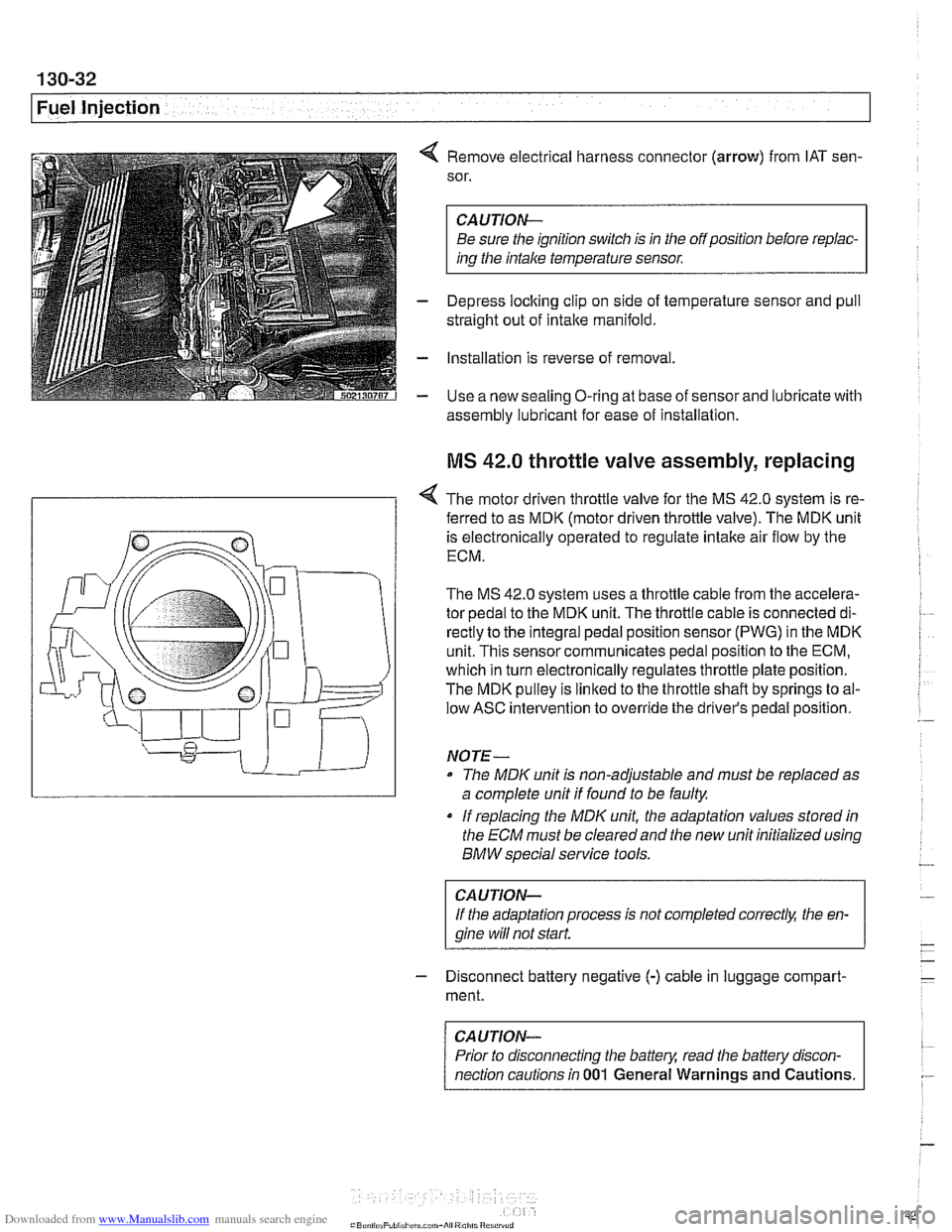
4 Remove electrical harness connector (arrow) from IAT sen-
sor.
CAUTION-
Be sure the ignition switch is in the off position before repiac-
ins the intake temperature sensor.
- Depress loclting clip on side of temperature sensor and pull
straight out of intake manifold.
- Installation is reverse of removal
- Use a new sealing O-ring at base of sensor and lubricate with
assembly lubricant for
ease of installation
MS 42.0 throttle valve assembly, replacing
< The motor driven throttle valve for the MS 42.0 system is re-
- ferred to as MDK (motor driven throttle valve). The MDK unit
is electronically operated to regulate intake air flow by the
ECM.
The
MS 42.0 system uses a throttle cable from the accelera-
tor pedal to the MDK unit. The throttle cable is connected di-
rectly to the integral pedal position sensor
(PWG) in the MDK
unit. This sensor communicates pedal position to the ECM,
which in turn electronically regulates throttle plate position.
The MDK pulley is linked to the throttle shaft by springs to al-
low ASC intervention to override the driver's pedal position.
NO TE -
The MDIC unit is non-adjustable and must be replaced as
a complete unit if found to be faulty.
if replacing the
MDK unit, the adaptation values stored in
the ECM must be clearedand the new unit initialized using
BMW special service tools.
CAUTION-
If the adaptation process is not completed correct& the en-
gine wiii
not start.
- Disconnect battery negative (-) cable in luggage compart-
ment.
CAUTION-
Prior to disconnecting the battern read the battely discon-
nection cautions in
001 General Warnings and Cautions.
Page 425 of 1002
Downloaded from www.Manualslib.com manuals search engine
Fuel Injection
MS 43.0 throttle valve assembly, replacing
The electronic throttle valve assembly forthe MS43.0 system
is referred to as
EDK (electronic throttle valve). There is no
mechanical (cable) link between the accelerator pedal and
the throttle plate.
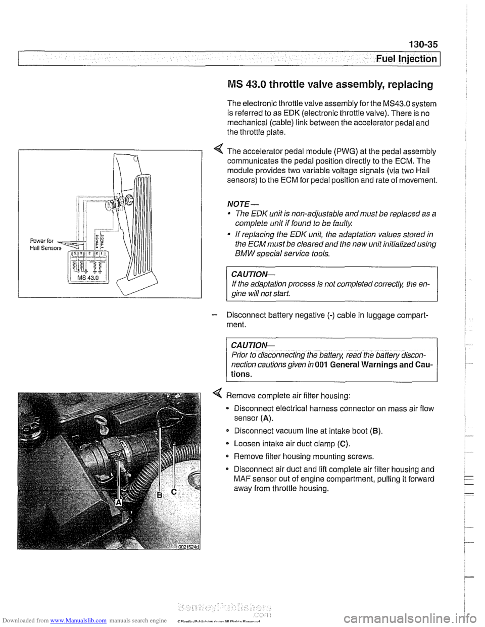
< The accelerator pedal module (PWG) at the pedal assembly
communicates the pedal position directly to the ECM. The
module provides two variable voltage signals (via two Hail
sensors) to the ECM for pedal position and rate of movement.
NOTE-
The EDK unit is non-adjustable and must be replaced as a
complete unit if found to be faulty
If replacing the
EDK unit, the adaptation values stored in
the
ECM must be cleared and the new unit initialized using
BMW special service tools.
CAUTIOIG
If the adaptation process is not completed correctk the en-
qine will not start
- Disconnect battery negative (-) cable in luggage compart-
ment.
CAUTION-
Prior to disconnecting the battery, read the battery discon-
nection cautions given in
001 General Warnings and Cau-
tions.
< Remove complete air filter housing:
- Disconnect electrical harness connector on mass air flow
sensor
(A).
Disconnect vacuum line at intake boot (6).
Loosen intaite air duct clamp (C).
Remove filter housing mounting screws.
Disconnect air duct and lift complete air filter housing and
MAF sensor out of engine compartment, pulling it forward
away from throttle housing.
Page 428 of 1002
Downloaded from www.Manualslib.com manuals search engine
130-38
Fuel Injection
Throttle cable, adjusting
(MS 42.0)
The throttle assembly on MS 42.0 cars uses a throttle cable.
The cable should be adjusted any time it is disconnected or
replaced. This procedure requires the factory scan tool or an
equivalent to read and adjust throttle angle. It is recommend-
ed the procedure be done by an authorized
BMW dealer ser-
vice department
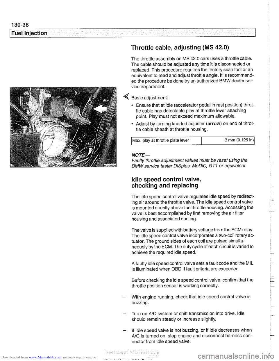
Basic adjustment:
Ensure that at idle (accelerator pedal in rest position) throt-
tle cable has detectable play at throttle lever attaching
point. Play must not exceed maximum allowable.
Adjust by turning knurled adjuster
(arrow) on end of throt-
tle cable sheath at throttle housing.
NOTE-
Faulty throttle adjustment values must be reset using the
BMW service tester
DISplus, MoDiC, GTI or equivalent.
Max.
play at throttle plate lever
ldle speed control valve,
checking and replacing
3 mm (0.125 in)
The Idle speed control valve regulates Idle speed by red~rect-
ing air around the throttle valve. The ldle speed control valve
is mounted
d~rectly above the throttle housing. Accessing the
valve is best accomplished by
flrst removing the air fllter
housing and associated ducting.
Thevalve is supplied with batteryvoltage from the ECM relay.
The idle speed control valve incorporates a two-coil rotary ac-
tuator. The ground sides of each coil are pulsed simulta-
neously by the ECM. The duty cycle of each circuit is varied to
achieve the required idle speed.
A faulty idle speed control valve sets a fault code and the MIL
is illuminated when
OED II fault criteria are exceeded.
Before checking the idle speed control valve, confirm that the
throttle position sensor is working correctly.
- With engine running, check that idle speed control valve is
buzzing.
- Turn on AIC system or shift transmission into drive. ldle
should remain steady or increase slightly.
- If idle speed valve is not buzzing, or if idle decreases when
AIC is turned on, stop engine and disconnect harness con-
nector from idle speed valve.
Page 430 of 1002
Downloaded from www.Manualslib.com manuals search engine
130-40
Fuel Injection
Engine control module (ECM),
removing and installing
The ECM uses stored functions and processing programs to
process the input signals from the sensors. These input sig-
nals are used to calculate the control (output) signals to the
actuators
(e.g., ignition coils, injectors).
NOTE-
Consult an authorized BMW dealer before replacing the
ECM.
- Disconnect negative (-) battery cable. Wait approximately
one minute.
CAUTION-
Prior to disconnecting the batteg read the battery discon-
nection cautions
in 001 General Warnings and Cautions.
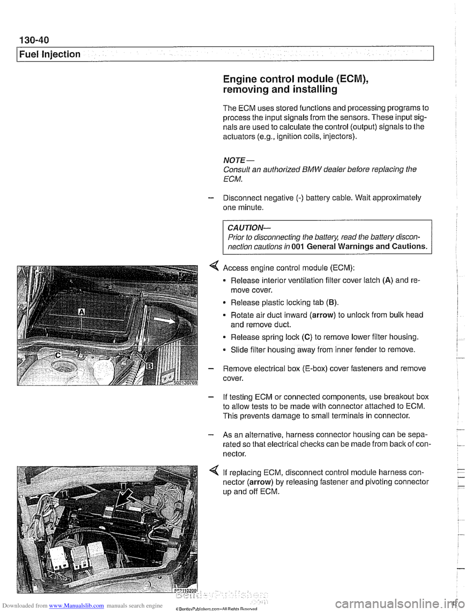
4 Access engine control module (ECM):
Release
interlor ventilation filter cover latch (A) and re-
move cover.
Release plastic loclting tab
(B).
Rotate air duct inward (arrow) to unloclt from bulk head
and remove duct.
Release spring lock
(C) to remove lower filter housing.
Slide
f~lter hous~ng away from inner fender to remove.
- Remove electrical box (E-box) cover fasteners and remove
cover.
- If testing ECM or connected components, use breakout box
to allow tests to be made with connector attached to ECM.
This prevents damage to small terminals in connector.
- - As an alternative, harness connector housing can be sepa-
rated so that electrical checks can be made from
back of con-
nector.
4 If replacing ECM, disconnect control module harness con-
nector (arrow) by releasing fastener and pivoting connector
up and off ECM.
Page 442 of 1002
Downloaded from www.Manualslib.com manuals search engine
.. .-
/Fuel lnjeciion
NOJE-
With engine oft disconnect harness connector and checlc
heating element resistance between white wires on the sen-
sor side of harness. If the element is electrically open (no
continuity), replace sensor.
- If oxygen sensor does not produce a fluctuating voltage and
preheater circuit is
OK, replace sensor.
NOJE-
If not already applied, coat oxygen sensor threads w~th anti-
seize compound before installat~on. Do not get the com-
pound on the sensor tip.
Tightening torque Oxygen sensor to exhaust system
55 Nm (41 ft-lb)
Fuel injectors, checking and replacing
The fuel iniectors are switched on and off (oaened and
closed)
by'the ECM. The injectors are connkcted to acom-
mon power source. A ground signal from the ECM is used to
open and close the injectors.
CA U JIOG
Use only a digital multimeter or an LED injector tester when
testing injectors or wiring. Use of an analog
VOM or incan-
descent test light may damaqe the engine controlmodule.
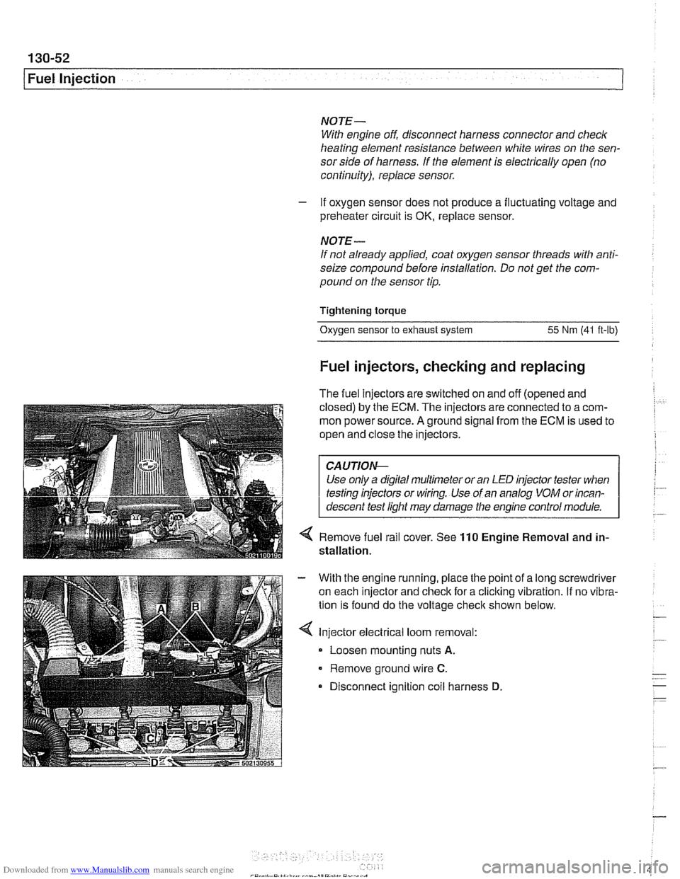
4 Remove fuel rail cover. See 110 Engine Removal and in-
stallation.
With the engine running, place the point of a long screwdriver
on each injector and check for a cliclting vibration.
If no vibra-
tion is found do the voltage
checit shown below.
Injector electrical loom removal:
- Loosen mounting nuts A.
Remove ground wire C.
Disconnect ignition coil harness D
Page 443 of 1002
Downloaded from www.Manualslib.com manuals search engine
Fuel Injection I
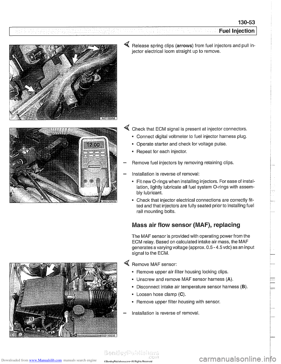
4 Release spring clips (arrows) from fuel injectors and pull in-
jector electrical loom straight up to remove.
4 Check that ECM signal is present at injector connectors.
- Connect digital voltmeter to fuel injector harness plug.
Operate starter and
check for voltage pulse.
* Repeat for each injector.
- Remove fuel injectors by removing retaining clips
- Installation is reverse of removal:
Fit new O-rings when installing injectors. For ease of instal-
lation, lightly lubricate all fuel system O-rings with assem-
bly lubricant.
Check that injector electrical connections are correctly fit-
ted and that
injectors are fully seated prior to installing iuel
rail mounting bolts.
Mass air flow sensor (MAF), replacing
The MAF sensor is provided with operating power from the
ECM relay. Based on calculated intake air mass, the MAF
generates
avarying voltage (approx. 0.5 - 4.5 vdc) as an input
signal to the ECM.
4 Remove MAF sensor:
Remove upper air filter housing locking clips.
Unscrew and remove MAF sensor harness
(A).
Disconnect intake air temperature sensor harness (B).
Loosen hose clamp (C).
Remove upper filter housing with sensor.
- Installation is reverse of removal
Page 444 of 1002
Downloaded from www.Manualslib.com manuals search engine
130-54
I Fuel Injection ldle speed control valve,
testing and replacing
ldle speed is maintained by the ECM through the idle speed
control valve. The idle control function compensates for en-
gine load and engine operating conditions. ldle speed is
adaptive through the ECM and no adjustments can be made.
Before checking valve, confirm that throttle position sensor is
working correctly.
NOTE-
The test given below is an electrical check only. It does not
check the mechanical operation of the valve. If the valve is
sticking, hanging up or is sluggish in operation, substituting a
Inown good valve is the best way to check it.
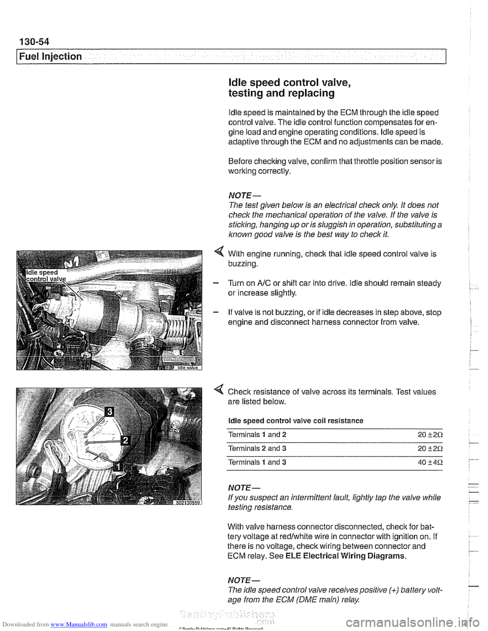
With engine running, check that idle speed control valve is
buzzing.
Turn on
AIC or shift car into drive. ldle should remain steady
or increase slightly.
If valve is not buzzing, or if idle decreases in step above, stop
engine and disconnect harness connector from valve.
4 Check resistance of valve across its terminals. Test values
are listed below.
ldle speed control valve coil resistance
Terminals
1 and 2 20 +2%
Terminals 2 and 3 20 +2Q
Terminals 1 and 3 40 +4%
NOTE-
If you suspect an intermittent fault, lightly tap the valve while
testing resistance.
With valve harness connector disconnected, check for bat-
tery voltage at redlwhite wire in connector with ignition on.
If . ~~ ~~
there is no voltage, check wiring between connector and 7 ECM relay. See ELE Electrical Wiring Diagrams.
NOTE- - The idle speed control valve receivespositive (+) battery volt-
age from the ECM (DME main) relay
Page 445 of 1002
Downloaded from www.Manualslib.com manuals search engine
Fuel Injection
- If voltage is present as described above, check wiring be-
tween ECM and valve. If no wiring faults are found, check
ECM signal to valve.
- When replacing idle speed control valve, clean and inspect
all sealing areas.
. Inspect sealing ring in throttle body and replace if neces-
sary.
Throttle position sensor (TPS),
testing and replacing
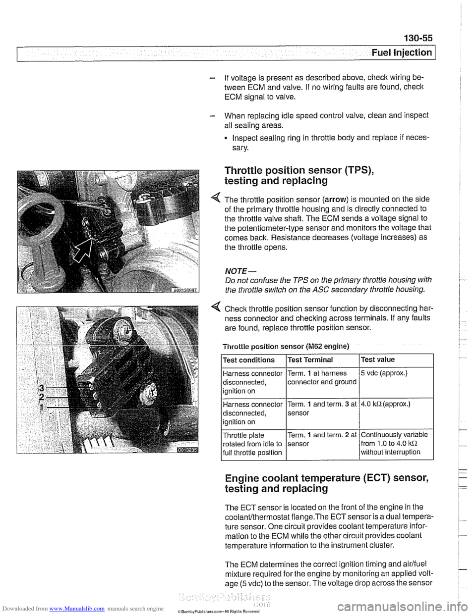
The throttle position sensor (arrow) is mounted on the side
of the primary throttle housing and is directly connected to
the throttle valve shaft. The ECM sends a voltage signal to
the potentiometer-type sensor and monitors the voltage that
comes back. Resistance decreases (voltage increases) as
the throttle opens.
NOTE-
Do not confuse the TPS on the primary throttle housing with
the throttle switch on the
ASC secondary throttle housing.
4 Check throttle position sensor function by disconnecting har-
ness connector and checking across terminals. If any faults
are found, replace throttle position sensor.
Engine coolant temperature (ECT) sensor,
testing and replacing
Throttle position sensor (M62 engine)
The ECT sensor is located on the front of the engine in the
coolanVthermostat flange.The ECTsensor is a dual tempera-
ture sensor. One circuit provides coolant temperature infor-
mation to the ECM while the other circuit provides coolant
temperature information to the instrument cluster.
The ECM determines the correct ignition timing and
airlfuel
mixture required for the engine by monitoring an applied volt-
age
(5 vdc) to the sensor. The voltage drop across the sensor
Test
value
5 vdc (approx.)
4.0 kR(approx.)
Continuously variable
from
1.0 to 4.0 kR
without interruption
Test
conditions
Harness connector
disconnected, ignition on
Harness connector
disconnected,
ignition on
Throttle plate rotated from idle to
full throttle position Test Terminal
Term.
1 at
harness
connector and ground
Term.
1 and term. 3 at
sensor
Term.
1 and term. 2 at
sensor
Page 447 of 1002
Downloaded from www.Manualslib.com manuals search engine
Fuel Injection
Intake air temperature
([AT) sensor,
testing and replacing
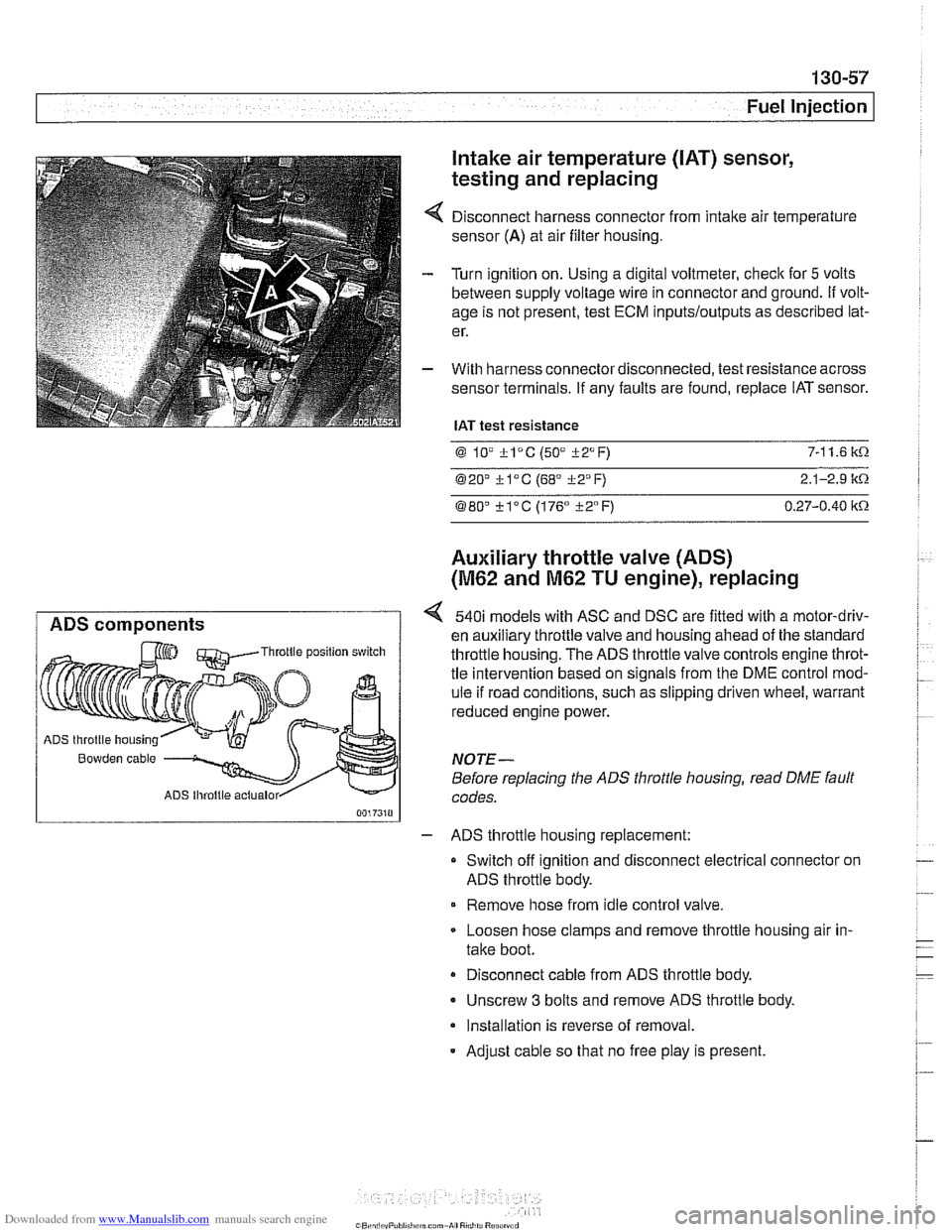
Disconnect harness connector from intake air temperature
sensor
(A) at air filter housing.
Turn ignition on. Using a digital voltmeter, check for
5 volts
between supply voltage wire in connector and ground.
If volt-
age is not present, test ECM
inputs/outputs as described lat-
er.
With harness connector disconnected, test resistance across
sensor terminals. If any faults are found, replace IAT sensor.
IAT test resistance
0 lV *lac (50" i-2°F) 7-1 1.6 k.0.
020' kl°C (68' 322°F) 2.1-2.9 it.0.
080" ?lac (176" i-2°F) 0.27-0.40 itn
Auxiliary throttle valve (ADS)
(M62 and M62 TU engine), replacing
ADS components 540i models with ASC and DSC are fitted with a motor-driv-
en auxiliary throttle valve and housing ahead of the standard Throttle position switch throttle housing. The ADS throttle valve controls engine throt-
tle intervention based on signals from the DME control mod-
ule if road conditions, such as slipping driven wheel, warrant
reduced engine power.
ADS throttle housing
Bowden cable NOTE-
Before replacing the ADS throttle housing, read DME fault
ADS lhroltle actualor codes.
- ADS throttle housing replacement:
Switch off ignition and disconnect electrical connector on
ADS throttle body.
Remove hose from idle control valve.
Loosen hose clamps and remove throttle housing air in-
take boot.
Disconnect cable from ADS throttle body.
- Unscrew 3 bolts and remove ADS throttle body.
Installation is reverse of removal.
- Adjust cable so that no free play is present.