replacing BMW 540i 1997 E39 Service Manual
[x] Cancel search | Manufacturer: BMW, Model Year: 1997, Model line: 540i, Model: BMW 540i 1997 E39Pages: 1002
Page 399 of 1002
Downloaded from www.Manualslib.com manuals search engine
Fuel Injection I
Mass air flow (MAF) sensor,
checking and replacing
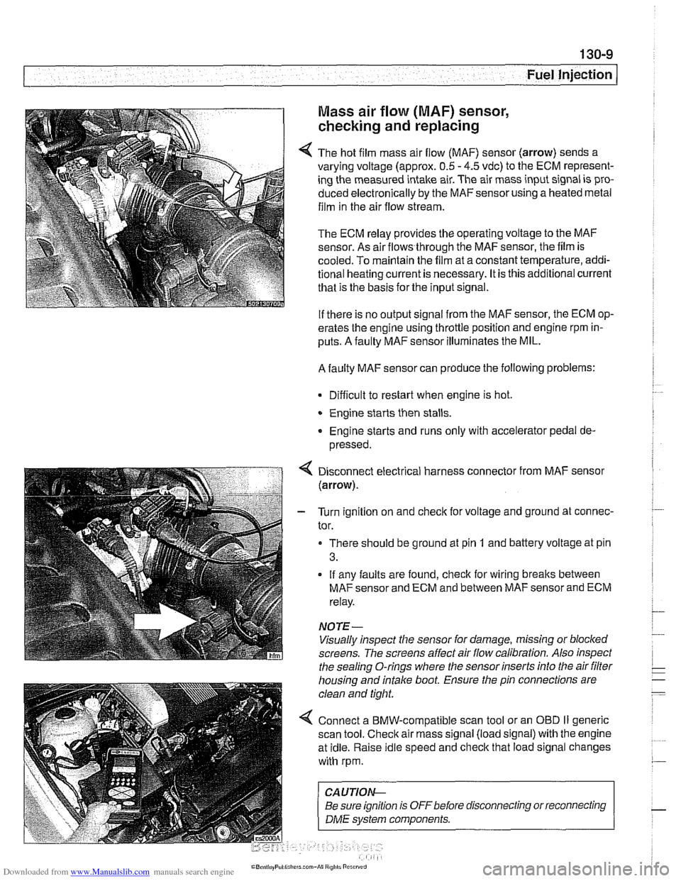
4 The hot film mass air flow (MAF) sensor (arrow) sends a
varying voltage (approx.
0.5 - 4.5 vdc) to the ECM represent-
ing the measured intake air. The air mass input signal is pro-
duced electronically by the
MAFsensorusing a heated metal
film in the air flow stream.
The ECM relay provides the operating voltage to the MAF
sensor. As air flows through the MAF sensor, the film is
-
cooled. To maintain the film at a constant temperature, addi-
tional heating current is necessary. It is this additional current
that is the basis for the input signal.
If there is no output signal from the MAF sensor, the ECM op-
erates the engine using throttle position and engine rpm in-
puts. A faulty MAF sensor illuminates the MIL.
A faulty MAF sensor can produce the following problems:
Difficult to restart when engine is hot.
Engine starts then stalls.
Engine starts and runs only with accelerator pedal de-
pressed.
Disconnect electrical harness connector from MAF sensor
(arrow).
- Turn ignition on and check for voltage and ground at connec-
tor.
There should be ground at pin
1 and battery voltage at pin
3.
If any faults are found, check for wiring breaks between
MAF sensor and ECM and between MAF sensor and ECM
relay.
NOTE-
Visually inspect the sensor for damage, missing or blocked
screens. The screens affect air flow calibration. Also inspect
the sealing O-rings where the sensor inserts into the air
filter
housing and intake boot. Ensure the pin connections are
clean and tight.
4 Connect a BMW-compatible scan tool or an OBD II generic
scan tool. Check air mass signal (load signal) with the engine
at idle. Raise idle speed and check that load signal changes
with rpm.
CA UTIOI\C
Be sure ignition is OFFbefore disconnecting or reconnecting r
1 DME svstem components. 1
Page 400 of 1002
Downloaded from www.Manualslib.com manuals search engine
130-1 0
Fuel Injection
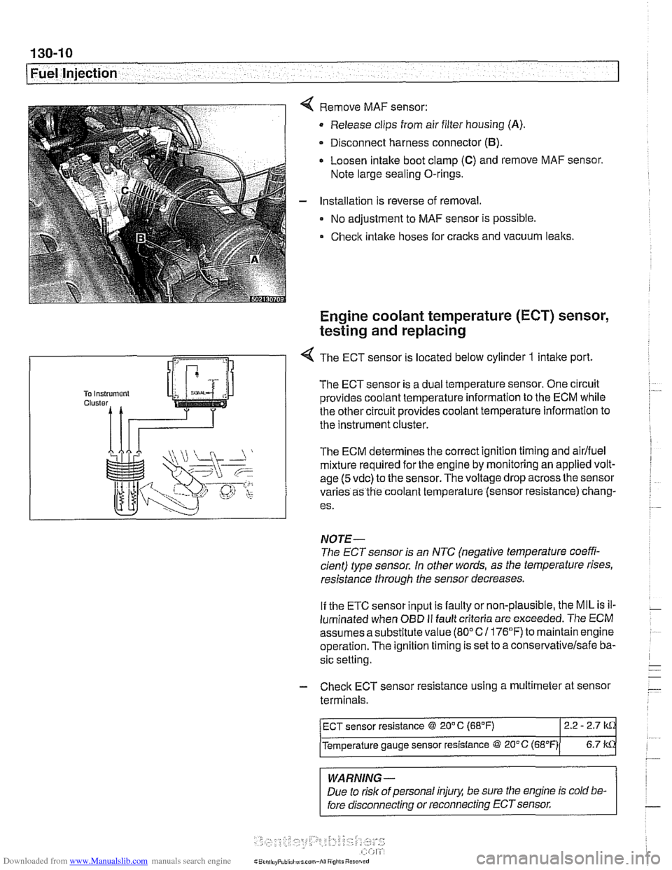
Remove MAF sensor:
Release clips from air filter housing
(A).
Disconnect harness connector (B).
Loosen intake boot clamp (C) and remove MAF sensor.
Note large sealing O-rings.
Installation is reverse of removal.
No adjustment to MAF sensor is possible.
Check intake hoses for cracks and vacuum leaks.
Engine coolant temperature (ECT) sensor,
testing and replacing
R
1 -4 The ECT sensor is located below cylinder 1 intake port
The ECT sensor is a dual temperature sensor. One circuit
provides coolant temperature information to the ECM while
the other circuit provides coolant temperature information to
the instrument cluster.
The ECM determines the correct ignition timing and
airlfuel
mixture required for the engine by monitoring an applied volt-
age
(5 vdc) to the sensor. The voltage drop across the sensor
varies as the coolant temperature (sensor resistance) chang-
es.
NOTE-
The ECT sensor is an NTC (negative temperature coeffi-
cient) type sensor. in other words, as the temperature rises,
resistance through the sensor decreases.
If the ETC sensor input is faulty or non-plausible, the MIL is il-
luminated when
OED II fault criteria are exceeded. The ECM
assumes asubstitute value
(80°C1 176°F) to maintainengine
operation. The ignition timing is set to a
conse~ativelsafe ba-
sic setting.
- Check ECT sensor resistance using a multimeter at sensor
terminals.
-
WARNING -
Due to risk of personal injury, be sure the engine is cold be-
fore disconnecting or reconnecting ECT sensor.
ECT sensor resistance @ 20" C (68°F) 2.2 - 2.7
Temperature gauge sensor resistance @ 20°C (~B"F)( 6.7 k
Page 401 of 1002
Downloaded from www.Manualslib.com manuals search engine
Fuel Injection
CAUTION-
Be sure ignition is OFF before disconnecting or reconnecting
DME system components.
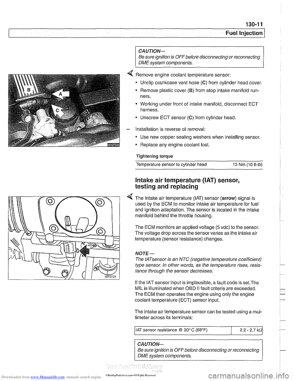
Remove engine coolant temperature sensor:
Unclip crankcase vent hose
(C) from cylinder head cover.
Remove plastic cover
(6) from atop intake manifold run-
ners.
Working under front of intake manifold, disconnect ECT
harness.
Unscrew ECT sensor
(C) from cylinder head.
Installation is reverse of removal:
Use new copper sealing washers when installing sensor.
Replace any engine coolant lost.
Tightening torque
Temperature sensor to cylinder head
13 Nm (10 it-lb)
Intake air temperature ([AT) sensor,
testing and replacing
4 The intake air temperature (IAT) sensor (arrow) signal is
used by the ECM to monitor intake air temperature for fuel
and
igntion adaptation. The sensor is .ocared in rne 'ntane
man:lold behind the throttle housng.
The ECM monitors an applied voltage (5 vdc) to the sensor
The voltage drop across the sensor varies as the intake air
temperature (sensor resistance) changes.
NOJE-
The IATsensor is an NTC (negative temperature coefficient)
type sensor. In other words, as the temperature rises, resis-
tance through the sensor decreases.
If the IAT sensor input is implausible, a
fault code is set.The
MIL is illuminated when OED II fault criteria are exceeded.
The ECM then operates the engine using only the engine
coolant temperature (ECT) sensor input.
The intake air temperature sensor can be tested using a
mul-
timeter across its terminals:
/ IAT sensor resistance @ 20" C (68°F) / 2.2 - 2.7 lkCk
~ -- ~~ -
CAUTION--
Be sure ignition is
OFFbefore disconnecting or reconnecting
DME system components.
Page 402 of 1002
Downloaded from www.Manualslib.com manuals search engine
130-1 2
Fuel Injection
- Disconnect intake air boot from throttle housing. Unbolt throt-
tle housing and lay aside. It is not necessary to disconnect
throttle cable or electrical harness connectors from throttle housing.
- Remove electrical harness connector from IAT sensor.
- Unclip temperature sensor and remove from intake manifold.
- Installation is reverse of removal. Use a new gasket at throttle
housing.
Throttle position sensor (TPS),
testing and replacing
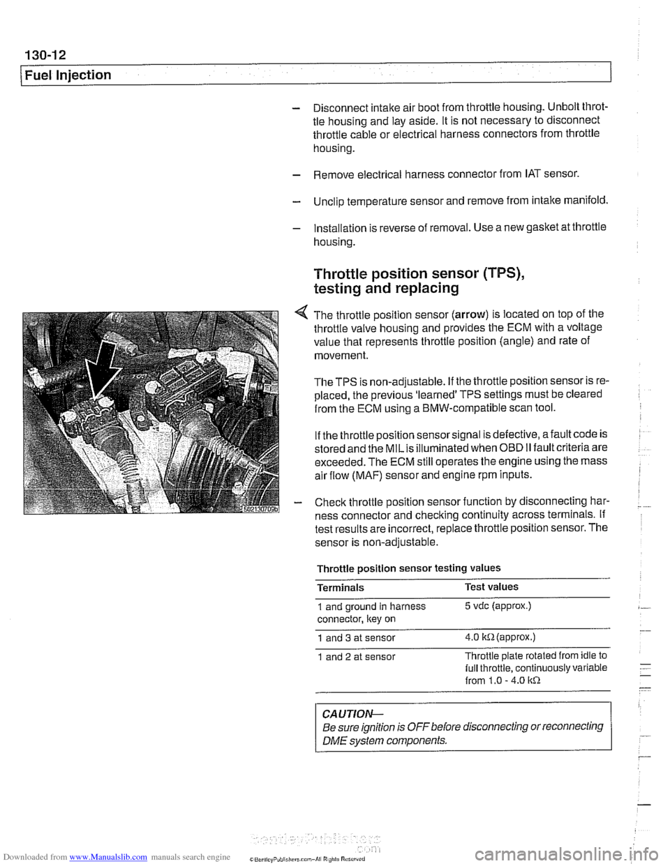
4 The throttle position sensor (arrow) is located on top of the
throttle valve housing and provides the ECM with a voltage
value that represents throttle position (angle) and rate of
movement.
TheTPS is non-adjustable. If the throttle position sensor is re-
placed, the previous 'learned' TPS settings must be cleared
from the ECM using a BMW-compatible scan tool.
If the throttle position sensor signal is defective, afault code is
stored and the
MILis illuminated when OBD II fault criteria are
exceeded. The ECM still operates the engine using the mass
air flow
(MAF) sensor and engine rpm inputs.
- Check throttle position sensor function by disconnecting har-
ness connector and checking continuity across terminals. If
test results are incorrect,
replace throttle position sensor. The
sensor is non-adjustable.
Throttle
~osition sensor testina values -
Terminals Test
values
1 and ground in harness 5 vdc (approx.)
connector, ltey on
1 and 3 at sensor 4.0 itR(appr0x.)
1 and 2 at sensor Throttle
plate rotated from idle to
lull throttle, continuously variable
from 1.0
- 4.0 1tR
CAUTION-
Be sure ignition is OFF before disconnecting or reconnecting
DME svstem components. r
Page 403 of 1002
Downloaded from www.Manualslib.com manuals search engine
130-1 3
Fuel Injection I
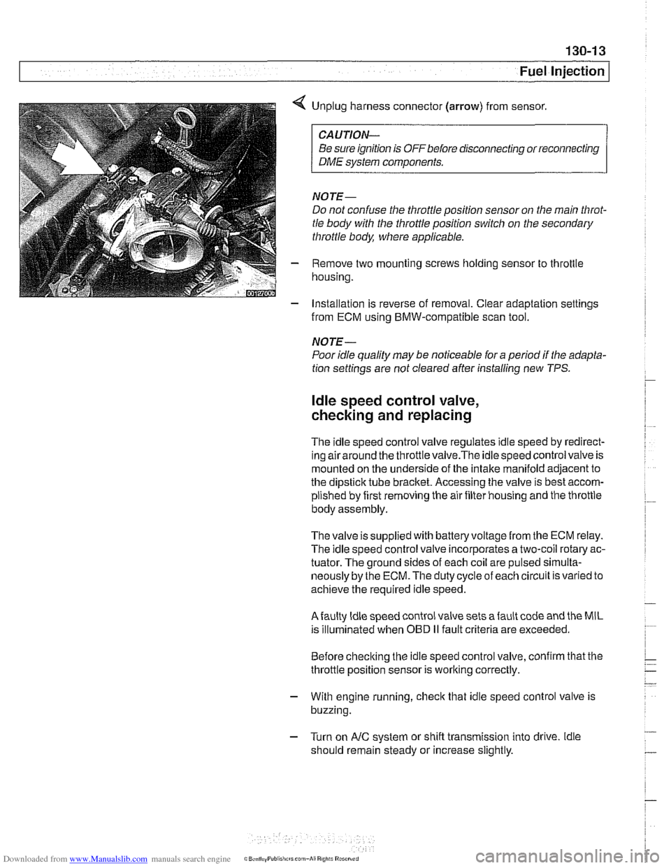
< Unplug harness connector (arrow) from sensor.
CAUTION-
Be sure ignition is OFF before disconnecting or reconnecting
DME system components.
NOTE-
Do not confuse the throttle position sensor on the main Nirot-
tle body with the throttle position switch on the secondary
throttle body, where applicable.
- Remove two mounting screws holding sensor to throttle
housing.
- Installation is reverse of removal. Clear adaptation settings
from ECM using BMW-compatible scan tool.
NOTE-
Poor idle quality may be noticeable for a period if the adapta-
tion settings are not cleared after installing new TPS.
ldle speed control valve,
checking and replacing
The idle speed control valve regulates idle speed by redirect-
inq airaround the throttlevalve.The idlespeed control valve is
mounted on the underside of the intake manifold adjacent to
the dipstick tube bracket. Accessing the valve is best accom-
plished by first removing the air filter housing and the throttle
body assembly.
The valve issupplied with
batteryvoltagefrom the ECM relay.
The idle speed control valve incorporates a two-coil rotary ac-
tuator. The ground sides of each coil are pulsed
sirnulta-
neously by the ECM. The duty cycle of each circuit is varied to
achieve the required idle speed.
Afaulty ldle speed control valve sets afault code and the MIL
is illuminated when
OED II fault criteria are exceeded.
Before checking the idle speed control valve, confirm that the
throttle position sensor is working correctly.
- With engine running, check that idle speed control valve is
buzzing.
- Turn on AIC system or shift transmission into drive. ldle
should remain steady or increase slightly.
Page 405 of 1002
Downloaded from www.Manualslib.com manuals search engine
Fuel injectors, checking and replacing
The fuel injectors are electronically controlled solenoid valves
that provide precisely metered and atomized fuel into the en-
gine intake ports.
The injectors receive voltage from the ECM relay. The ECM
controls the opening by activating the ground circuit
forthe in-
jector valve solenoids. The ECM varies the duration (in milli-
seconds) of "opening" time to regulate the
airlfuel ratio.
For a quick
check of the injectors, run the engine and touch
each injector with a screwdriver or stethoscope. You should
feel a vibration or hear a buzzing
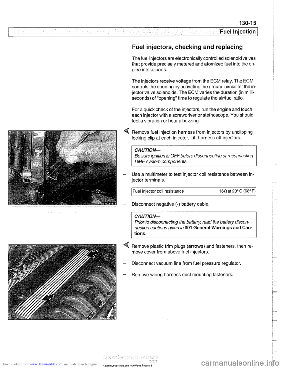
Remove fuel injection harness from injectors by unclipping
locking clip at each injector. Lift harness off injectors.
CA U JIOG
Be sure ignition is OFF before disconnecting or reconnecting
DME system components.
Use a multimeter to test injector coil resistance between in-
jector terminals.
l~uel injector coil resistance 16R at 20" C (68" F)
Disconnect negative
(-) battery cable
CAUTIOG
Prior to disconnecting the battery, read the battery discon-
nection cautionsgiven
in 001 General Warnings and Cau-
tions.
4 Remove plastic trim plugs (arrows) and fasteners, then re.
move cover from above fuel injectors.
- Disconnect vacuum line from fuel pressure regulator.
- Remove wiring harness duct mounting fasteners.
Page 408 of 1002
Downloaded from www.Manualslib.com manuals search engine
130-1 8
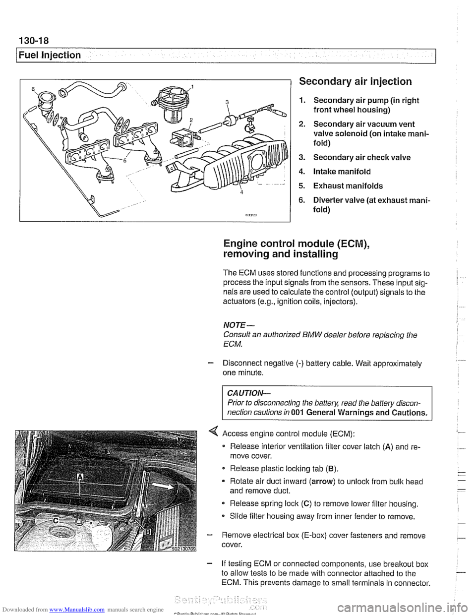
1 Fuel injection Secondary air injection
1. Secondary air pump (in right
front wheel housing)
2. Secondary air vacuum vent
valve solenoid (on intake mani-
fold)
3. Secondary air check valve
4. Intake manifold
5. Exhaust manifolds
6. Diverter valve (at exhaust mani-
fold)
Engine control module (ECM),
removing and installing
The ECM uses stored functions and processing programs to
process the input signals from the sensors. These input sig-
nals are used to calculate the control (output) signals to the
actuators
(e.g., ignition coils, injectors).
NOTE-
Consult an authorized BMW dealer before replacing the
ECM.
- Disconnect negative (-) battery cable. Wait approximately
one minute.
Prior to disconnecting the
battely, read the battery discon-
nection cautions in
001 General Warnings and Cautions.
Access engine control module (ECM):
Release interior ventilation filter cover latch
(A) and re-
move cover.
Release plastic locking tab
(B).
Rotate air duct inward (arrow) to unloclc from bulk head
and remove duct.
Release spring lock
(C) to remove lower filter housing.
Slide filter housing away from inner fender to remove.
- Remove electrical box (E-box) cover fasteners and remove
cover.
- If testing ECM or connected components, use breakout box
to allow tests to be made with connector attached to the
ECM. This prevents damage to small terminals in connector.
Page 409 of 1002
Downloaded from www.Manualslib.com manuals search engine
Fuel Injection I
- As an alternative, harness connector housing can be sepa-
rated so that electrical
checlts can be made from backof con-
nector.
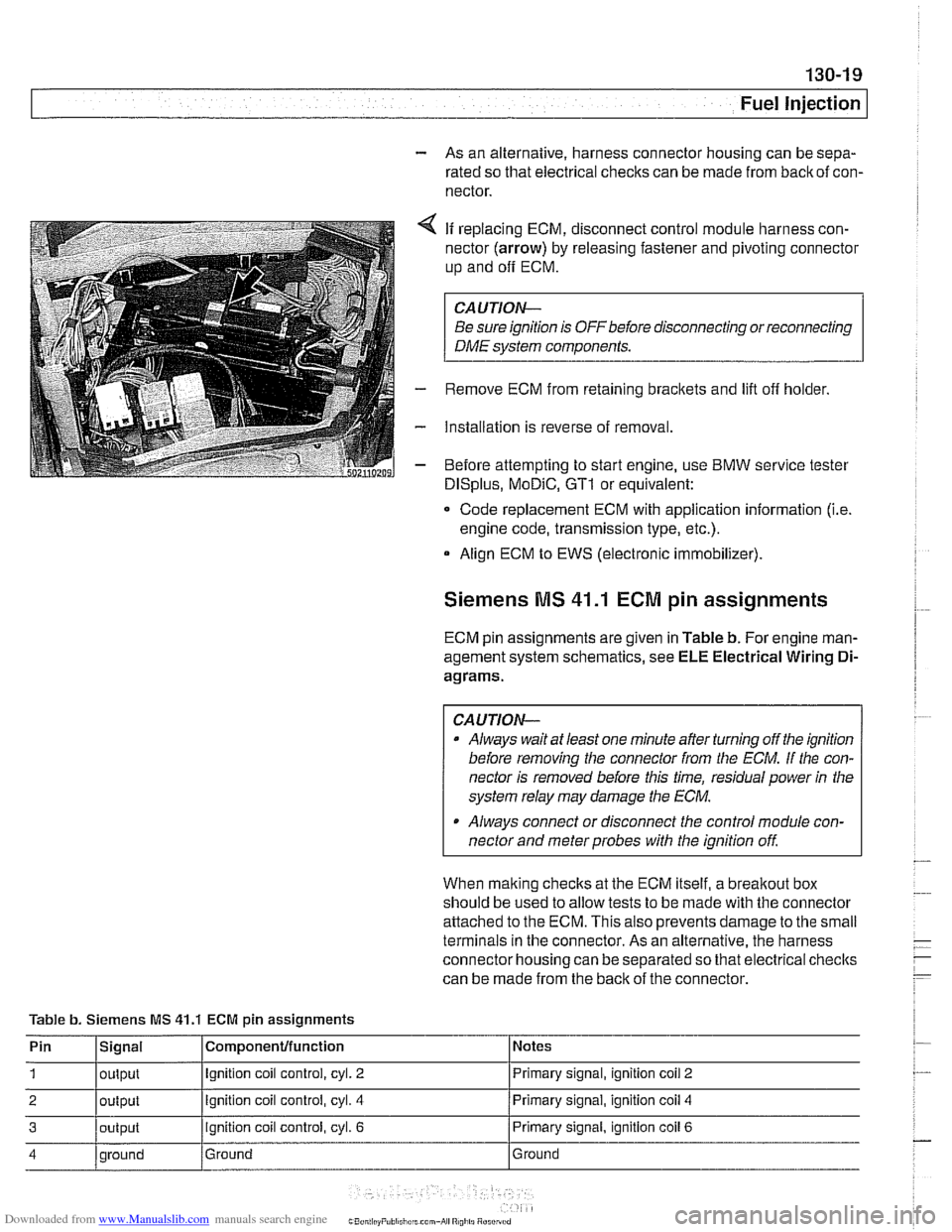
4 If replacing ECM, disconnect control module harness con-
nector (arrow) by releasing fastener and pivoting connector
up and
off ECM.
CAUTION-
Be sure ignition is OFF before disconnecting or reconnecting
DME system components.
- Remove ECM from retaining brackets and lift off holder.
- Installation is reverse of removal.
- Before attempting to start engine, use BMW service tester
DISplus, MoDiC, GTI or equivalent:
- Code replacement ECM with application information (i.e.
engine code, transmission type, etc.).
Align ECM to EWS (electronic immobilizer).
Siemens MS 41.1 ECM pin assignments
ECM pin assignments are given in Table b. For engine man-
agement system schematics, see ELE Electrical Wiring
Di-
agrams.
CAUTION-
a Always wait at least one minute after turning off the ignition
before removing the connector from the
ECM. If the con-
nector is removed before this time, residual power
in the
system relay may damage the
ECM.
Always connect or disconnect the control module con-
nector and meter probes with the ignition
off
When malting checks at the ECM itself, a breakout box
should be used to allow tests to be made with the connector
attached to the ECM. This also prevents damage to the small
terminals in the connector. As an alternative, the harness
connector housing can be separated so that electrical checlts
can be made from the back of the connector.
Table b. Siemens MS
41.1 ECM pin assignments
Pin
1
2
3
4
Signal
output
output
output
qround Componenfffunction
Ignition coil control, cyl. 2
Ignition coil control, cyl. 4
ignition coil control, cyl. 6
Ground Notes
Primary signal,
ignition
coil 2
Primary signal, ignition coil 4
Primary signal, ignition coil 6
Ground
Page 418 of 1002
Downloaded from www.Manualslib.com manuals search engine
130-28
Fuel Injection
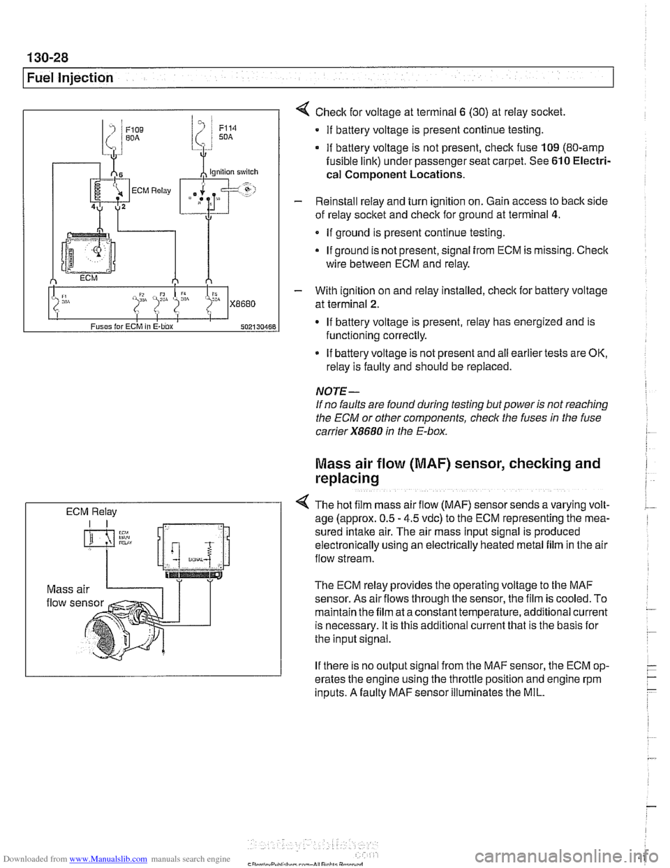
ECM Relay
4 Check for voltage at terminal 6 (30) at reiay socket
If battery voltage is present continue testing.
if battery voltage is not present, check fuse 109 (80-amp
fusible link) under passenger seat carpet. See 610 Electri-
cal
Component Locations.
- Reinstall relay and turn ignition on. Gain access to back side
of reiay socket and check for ground at terminal
4.
If ground is present continue testing.
If ground is not present, signal
from ECM is missing. Check
wire between ECM and relay.
- With ignition on and reiay installed, check lor battery voltage
at terminal
2.
If battery voltage is present, relay has energized and is
functioning correctly.
If battery voltage is not present and
ail earlier tests are OK,
relay is faulty and should be replaced.
NOTE-
If no faults are found during testing but power is not reaching
the ECM or other components, check the fuses
in the fuse
carrier
X8680 in the E-box.
Mass air flow (MAF) sensor, checking and
replacing
4 The hot f~lm mass air flow (MAF) sensor sends a varying volt-
age (approx. 0.5 - 4.5 vdc) to the ECM representing the mea-
sured
Intake air. The alr mass input signal is produced
electron~caily uslng an electrically heated metal fllm in the air
flow stream.
The ECM relay provides the operating voltage to the MAF
sensor. As air
flows through the sensor, the film is cooled. To
maintain the film at a constant temperature, additional current
is necessary. It is this additional current that is the basis lor
the input signal.
If there is no output signal from the MAF sensor, the ECM op-
erates the engine using the throttle position and engine rpm
inputs. A faulty MAF sensor illuminates the MIL.
Page 420 of 1002
Downloaded from www.Manualslib.com manuals search engine
Fuel Injection
Engine coolant temperature
(ECT) sensor,
testing and replacing
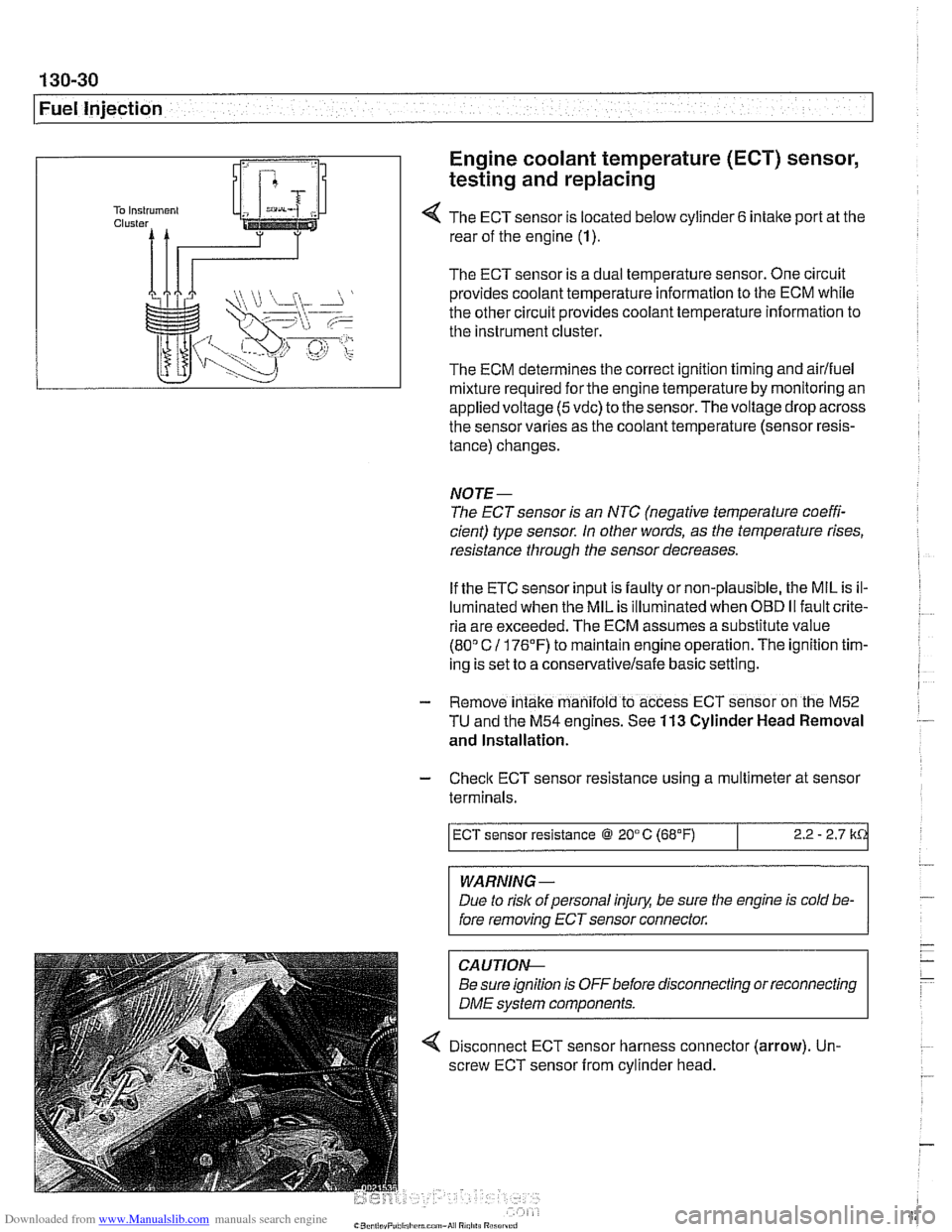
4 The ECT sensor is located below cylinder 6 intake port at the
rear of the engine (1).
The ECT sensor is a dual temperature sensor. One circuit
provides coolant temperature information to the ECM while
the other circuit provides coolant temperature information to
the instrument cluster.
The ECM determines the correct ignition timing and airlfuel
mixture required
forthe engine temperature by monitoring an
appliedvoltage
(5vdc) to the sensor.Thevoltage drop across
the sensor varies as the coolant temperature (sensor resis-
tance) changes.
NOTE-
The ECT sensor is an NTC (negative temperature coeffi-
cient) type sensor. In other words, as the temperature rises,
resistance through the sensor decreases.
If the ETC sensor input is faulty or non-plausible, the MIL is il-
luminated when the MIL is illuminated when
OED II fault crite-
ria are exceeded. The ECM assumes a substitute value
(80" C 11 76'F) to maintain engine operation. The ignition tim-
ing is set to a
conservativelsafe basic setting.
- Remove intake manifold to access ECT sensor on the M52
TU and the M54 engines. See 113 Cylinder Head Removal
and Installation.
- Check ECT sensor resistance using a multimeter at sensor
terminals.
WARNING -
Due to rislc of personal injury, be sure the engine is cold be-
fore removing ECT sensor connector.
ECT sensor resistance @ 20°C (68°F)
CAUTIOI\C
Be sure ignition is OFFbefore disconnecting or reconnecting
DME svstem components.
2.2 - 2.7 k
4 Disconnect ECT sensor harness connector (arrow). Un-
screw ECT sensor from cylinder head.