Wir BMW 540i 1997 E39 Manual PDF
[x] Cancel search | Manufacturer: BMW, Model Year: 1997, Model line: 540i, Model: BMW 540i 1997 E39Pages: 1002
Page 381 of 1002
Downloaded from www.Manualslib.com manuals search engine
Battery, Starter, ~lternatorl
Alternator, removing and installing
(6-cylinder engine)
A replacement alternator should have the same rating as the
original. Alternator manufacturer and ampere rating are nor-
mally marked on the alternator housing.
- Disconnect negative (-) battery cable.
CAUTION-
Prior to disconnecting the batteg read the battery discon-
nection cautions given
in 001 General Warnings and Cau-
I tions.
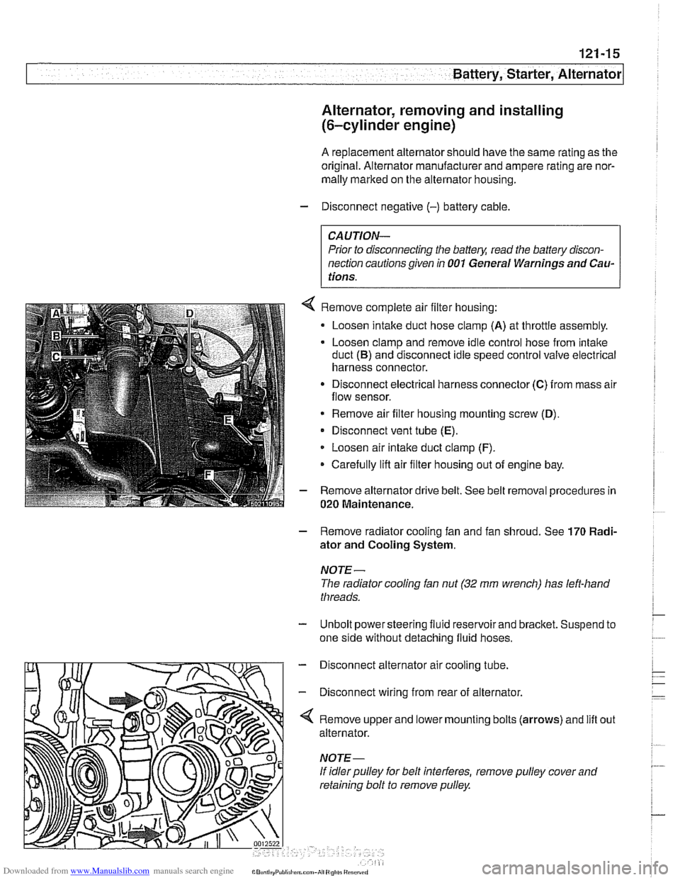
Remove complete air filter housing:
Loosen intake duct hose clamp
(A) at throttle assembly.
Loosen clamp and remove idle control hose from intake
duct
(B) and disconnect idle speed control valve electrical
harness connector.
Disconnect electrical harness connector
(C) from mass air
flow sensor.
* Remove air filter housing mounting screw (D),
Disconnect vent tube (E).
Loosen air intake duct clamp (F).
Carefully lifl air filter housing out of engine bay.
Remove alternator drive belt. See belt removal procedures in
020 Maintenance.
- Remove radiator cooling fan and fan shroud. See 170 Radi-
ator and Cooling System.
NOTE-
The radiator cooling fan nut (32 mm wrench) has left-hand
threads.
- Unbolt power steering fluid reservoir and bracket. Suspend to
one side without detaching fluid hoses.
- Disconnect alternator air cooling tube.
- Disconnect wiring from rear of alternator.
'4 Remove upper and lower mounting bolts (arrows) and lift
alternator.
If idler pulley for belt interferes, remove pulley cover and
retaining bolt to remove pulley. out
Page 382 of 1002
Downloaded from www.Manualslib.com manuals search engine
121-16
Battery, Starter, Alternator
- installation is reverse of removal.
Tightening torques Belt tensloner to engine block
M8 (8.8 grade) 22
Nm (16 ft-ib)
Fan clutch to coolant pump
with BMW special tool 11
5 040 30 Nm (22
ft-lb)
without BMW special tool
11 5 040 40 Nm
(29 ft-ib)
Pulley to alternator 70
Nm (44 ft-lb)
Terminal 30
(B+) wire to alternator (M8) 13 Nm (10 ft-ib)
Alternator, removing and installing
(M62 engine, air cooled)
A replacement alternator should have the same rating as the
original. Alternator manufacturer and ampere rating are nor-
mally
marked on the alternator housing.
- Disconnect negative (-) battery cable.
CAUTION-
Prior to disconnecting the battery, read the battery discon-
nection cautions
001 General Warnings and Cautions.
- Remove cooling fan and alternator drive belt. See 020 Main-
tenance.
- Pry out trim caps and remove fasteners from plastic cover on
left head. Lift off cover.
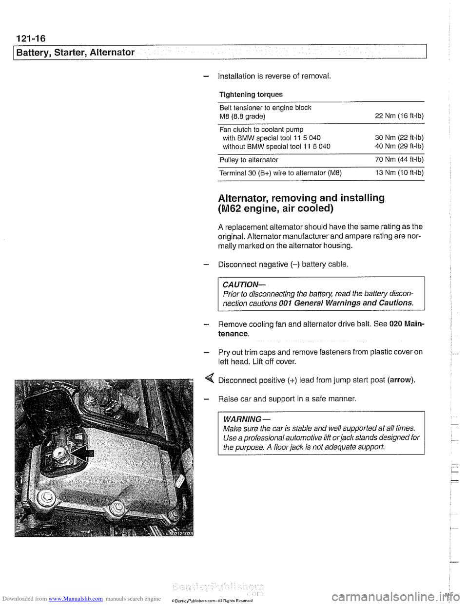
Disconnect positive
(+) lead from jump start post (arrow).
Raise car and support in a safe manner.
WARNING-
Make sure the car is stable and well supported at aN times.
Use a professional automotive lift
orjack stands designed for
the purpose.
A floorjack is not adequate support.
Page 383 of 1002
Downloaded from www.Manualslib.com manuals search engine
121-17
Bauery, Starter, Alternator
- Remove engine splash shield from underneath car.
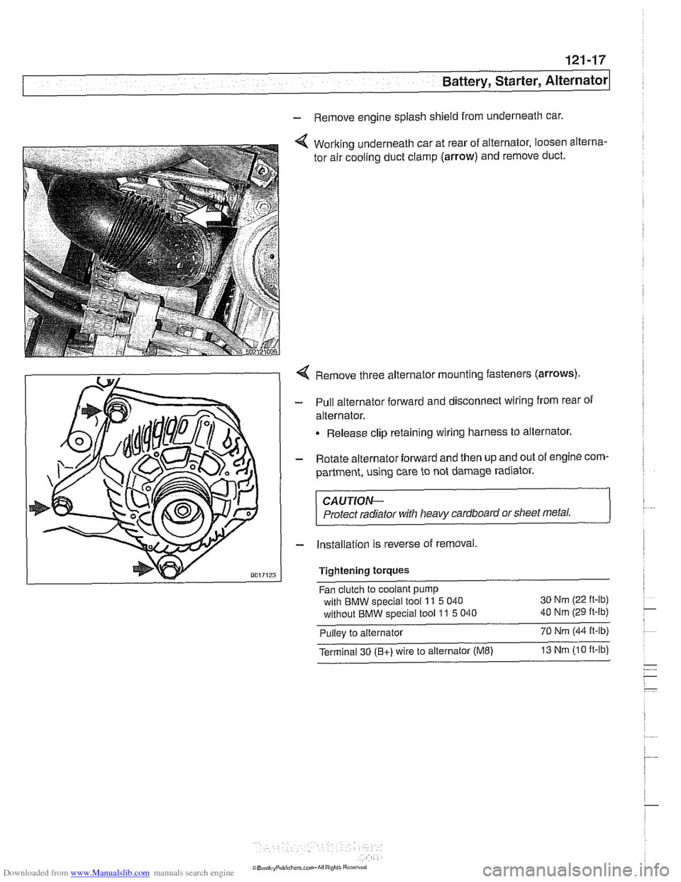
Working underneath car at rear of alternator, loosen alterna-
tor air cooling duct clamp
(arrow) and remove duct.
Remove three alternator mounting fasteners
(arrows)
Pull alternator forward and disconnect wiring from rear of
alternator.
Release clip retaining wiring harness to alternator.
Rotate alternator forward and then up and out of engine com-
partment, using care to not damage radiator.
CAUTIOe
Protect radiator with heavy cardboard or sheet metal.
Installation is reverse of removal,
Tightening
torques
Fan clutch to coolant pump
with BMW special tool
11 5 040 30
Nm (22 ft-lb)
without BMW special tool 11 5 040 40 Nm (29 ft-lb)
Pullev to alternator 70 Nm 144 it-lb) -,
Terminal 30 (Bt) wire to alternator (ME) 13 Nm 110 ft-lb
Page 385 of 1002
Downloaded from www.Manualslib.com manuals search engine
Battery, Starter, Alternator
- Installation is reverse of removal, noting the following:
Replace alternator rubber sealing O-ring.
* Fill and bleed cooling system as described in 170 Radiator
and Cooling System.
Tightening torques
Fan clutch to coolant pump
with
BMW special tool 11 5 040 30 Nm (22 ft-lb)
without
BMW special tool 11 5 040 40 Nm (29 ft-lb)
Terminal 30 (Bc) wire to alternator (ME) 13 Nm (10 ft-lb)
STARTER
Starter troubleshooting
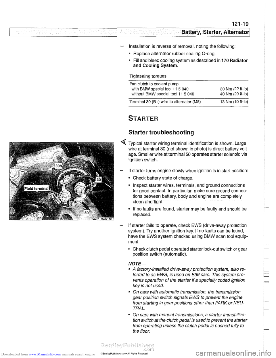
Typical starter wiring terminal identification is shown. Large
wire at terminal
30 (not shown in photo) is direct battery volt-
age. Smaller wire at terminal
50 operates starter solenoid via
ignition switch.
If starter turns engine slowly when ignition is in start position:
Check battery state of charge.
Inspect starter wires, terminals, and ground
connectlons
for good contact. In particular, make sure ground connec-
tions between battery, body and
englne are completely
clean and tight.
If no faults are found, starter may be faulty and should be
replaced.
- If starter fails to operate, check EWS (drive-away protection
system). Try another ignition key.
If no faults can be found,
have the EWS system checked using
BMW scan tool equip-
ment.
Checkclutch pedal operated
starter lock-out switch or gear
position switch (automatic).
NOTE-
* A factory-installed drive-away protection system, also re-
ferred to as
EWS, is used on E39 cars. This system pre-
vents operation of the starter if a specially coded ignition
key is not used.
On cars with automatic transmission, the transmission
gear position switch signals
EWS to prevent the engine
from starting in gear positions other than PARK or NEU-
TRAL.
On cars with manual transmissions, a starter immobiliza-
tion switch
at the clutch pedal is used to prevent the starter
from operating unless the clutch pedal is pushed fully to
the floor.
Page 386 of 1002
Downloaded from www.Manualslib.com manuals search engine
I Battery, Starter, Alternator
- Check for battery voltage at terminal 50 of starter motor with
key in start position. If voltage is not present, check wiring be-
tween ignition switch and starter terminal. Check the EWS
system and other inputs that disrupt terminal
56 to the start-
er. See ELE Electrical
Wiring Diagrams. If voltage is
present and no other visible wiring faults can be found, prob-
lem is most likely in starter motor.
Starter, removing and installing
(6-cylinder engine)
The starter is removed from below. Access to starter bolts is
difficult. Be sure to have the proper tools on hand before pro-
ceeding.
NOTE-
Access to the starter wiring is very limited. Forbetteraccess,
it may be necessary to remove the intake manifold.
- Disconnect negative (-) battery cable.
CAUTIOI\C
Prior to disconnecting the battern read the baltery discon-
nection cautions
in OOlGeneral Cautions and Warnings.
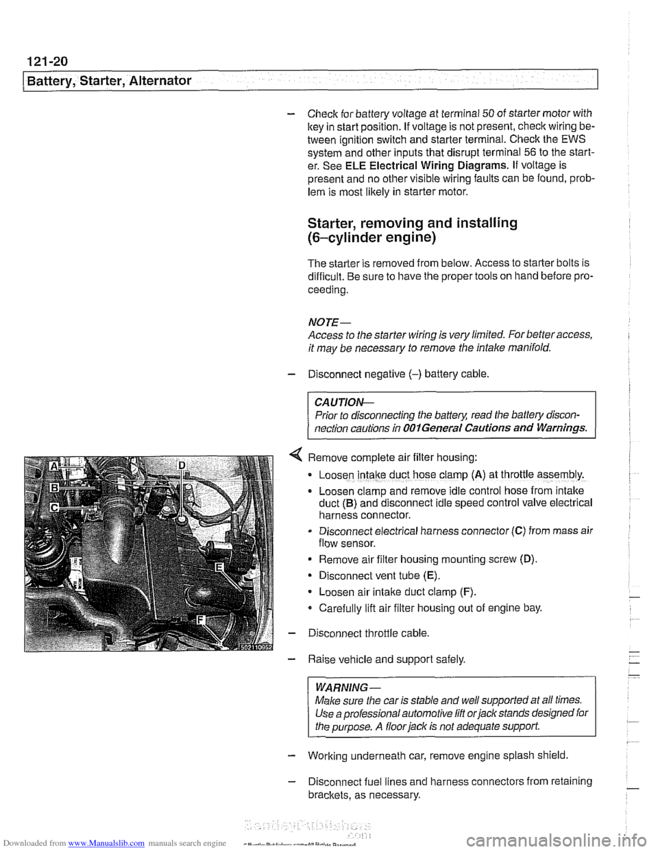
Remove complete air filter hous~ng:
Loosen intake duct hose clamp (A) at throttle assembly.
Loosen clamp and remove idle control hose from intake
duct
(B) and disconnect idle speed control valve electrical
harness connector.
Disconnect electrical harness connector
(C) from mass air
flow sensor.
Remove air filter housing mounting screw (D)
Disconnect vent tube
(E).
Loosen air intake duct clamp (F).
Carefully lift air filter housing out of engine bay.
Disconnect throttle cable.
Raise vehicle and support safely.
WARNING-
Make sure the car is stable and well supported at all times.
Use a professional automotive
lift orjack stands designed for
the purpose. A
floorjaclc is not adequate support
- Working underneath car, remove engine splash shield
- Disconnect fuel lines and harness connectors from retaining
brackets, as necessary.
Page 387 of 1002
Downloaded from www.Manualslib.com manuals search engine
Battery, Starter, ~lternatorl
- Disconnect wiring from starter.
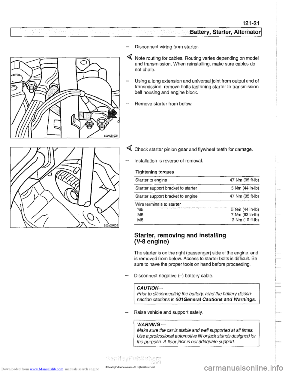
4 Note routing for cables. Routing varies depending on model
and transmission. When reinstalling, make sure cables do
not chafe.
- Using a long extension and universal joint from output end of
transmission, remove bolts fastening starter to transmission
bell housing and engine block.
- Remove starter from below
4 Checlc starter pinion gear and flywheel teeth for damage.
- Installation is reverse of removal.
Tightening torques
Starter to engine 47 Nrn (35 It-lb)
Starter sipport bracket to starter 5 Nrn (44 in-lb)
Starter support
bracket to engine 47 Nrn (35 ft-lb)
Wlre terminals to slarter
M5 5 Nrn (44 in-lb)
M6 7 Nrn (62 in-lb)
M8 13 Nrn (10 ft-lb)
Starter, removing and installing
(V-8 engine)
The starter is on the right (passenger) side of the engine, and
is removed from below. Access to starter bolts is difficult. Be
sure to have the proper tools on hand before proceeding.
- Disconnect negative (-) battery cable
CA UTIOW-
Prior to disconnecting the battery, read the battev discon-
nection cautions in
OOlGeneral Cautions and Warnings. -
- Raise vehicle and support safely.
/ WARNING- 1 ~ ~~ ~~ ~~~ ~
Make sure the car is stable and well supported at all times.
Use a professional automotive lift orjacltstands designed for
I the purpose. A floor jack is not adequate support I
Page 388 of 1002
Downloaded from www.Manualslib.com manuals search engine
-
Battery, Starter, Alternator
- Working underneath car, remove engine splash shield.
- Remove heat shield from starter.
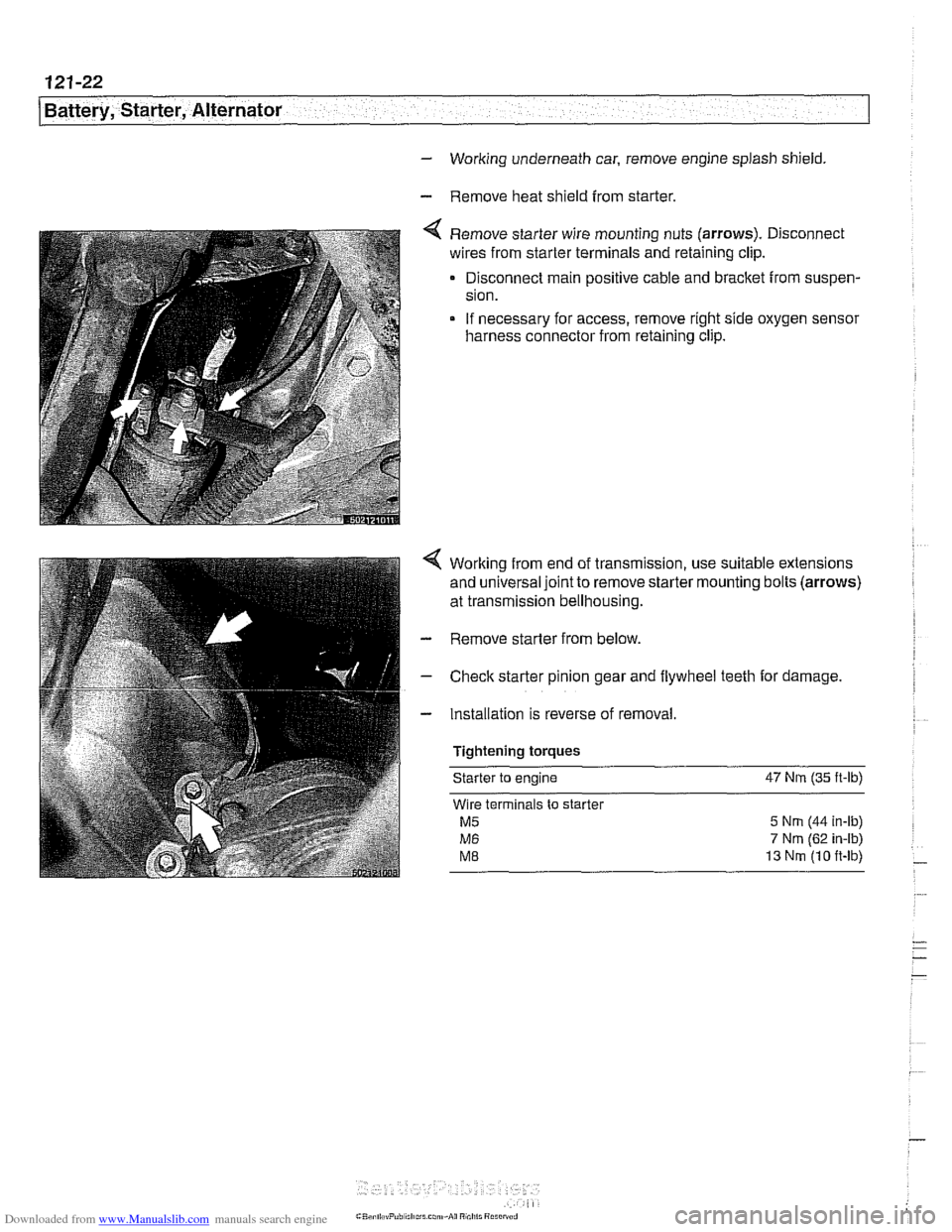
Remove starter wire mounting nuts (arrows). Disconnect
wires from starter terminals and retaining clip.
Disconnect main positive cable and bracket from suspen-
sion.
If necessary for access, remove right side oxygen sensor
harness connector from retaining clip.
Working from end of transmission, use suitable extensions
and universal joint to remove starter mounting bolts (arrows)
at transmission bellhousing.
- Remove starter from below.
- Check starter pinion gear and flywheel teeth for damage.
- Installation is reverse of removal
Tightening torques Starter
to engine 47 Nrn (35
ft-lb)
Wire terminals to starter
M5 5 Nrn (44 in-ib)
M6 7 Nm (62 in-ib)
ME 13 Nrn (10 ft-lb)
Page 395 of 1002
Downloaded from www.Manualslib.com manuals search engine
Fuel Injection
Warnings and cautions
For personal safety, as well as the protection of sensitive
electronic components, adhere to the warnings and cautions
on the following pages.
WARNING-
Gasoline is highly flammable and its vapors are explosive.
Do not smoke or work on a car near heaters or other fire
hazards when diagnosing and repairing fuel system prob-
lems. Have a fire extinguisher available in case of an emer-
gency
Renew fuel system hoses, clamps and O-rings any
time they are removed.
When working on an open fuel system, wear suitable
hand protection, as prolonged contact
with fuel can
cause illnesses and skin disorders.
* The ignition system produces high voltages that can be
fatal. Avoid contact with exposed terminals. Use ex-
treme caution when
working on a car with the ignition
switched on or the engine running.
CAUTION-
- Disconnecting the battery may erase fault code($ storedin
memory Check for fault codes prior to disconnecting the
battery cables. Read the battery disconnection cautions in
001 General Warnings and Cautions.
a Connect and disconnect the DME system wiring and
1 test equipment leads only when the ignition is switched
off.
Wait at least 1 minute after turning off the ignition be-
fore removing the engine control module (ECM) con-
nector. If the connector is removed before this time,
residualpower in the system relay may damage the
control module.
Fuel system cleaners and other chemical additives oth-
er than those specifically recommended by BMW may
damage the catalytic converter, the oxygen sensor or
other fuel supply components.
* Do not connect any test equipment that delivers a 12-
volt power supply to terminal 15 (+) of the ignition coil.
The current flow may damage the ECM. In general,
connect test equipment only as specified by BMW or
the equipment maker.
Only use a digital
multirneter for electrical tests. Only
use an LED test light for
quiclc tests.
Page 396 of 1002
Downloaded from www.Manualslib.com manuals search engine
130-6
Fuel Injection
Fuel supply to the injection system is provided by a high pres-
sure electric pump mounted inside the fuel tank. The pump is
powered via the fuel pump relay. If the relay is faulty, the fuel
pump will not run and the engine will not start.
NOTE-
* Fuel delivery volume and fuel pressure are critical to prop-
er operation. Fuel pressure direcfly influences fuel deliv-
ery
Fuel pump relay, fuel pressure and fuel volume tests are
given in 160 Fuel Tank and Fuel Pump.
Relieving system fuel pressure
The fuel system retains fuel pressure in the system when the
engine is off. To prevent fuel from spraying on a hot engine,
system fuel pressure should be relieved beforedisconnecting
fuel lines. One method is to tightly wrap
ashop towel around a
fuel line fitting and loosen or disconnect the fitting. Cleanli-
ness is essential when working with fuel components. Thor-
oughly clean the unions before disconnecting fuel lines.
When system faults are detected, a diagnostic trouble code
(DTC) is stored in the engine control module (ECM). The MIL
also iiluminates if an emissions-related fault is detected
When faults arise, or if the malfunction indicator lamp (MIL) is
illuminated, begin troubleshooting by connecting BMW ser-
vice tester
DISplus. MoDiC, GTI or equivalent scan tool. The
capabilities of OBD
II software has the potential to save hours
of diagnostic time and to help avoid incorrect component re-
placement and possible damage to system components.
CAUTION-
- The tests in this section may set fault codes (DTCs) in the
ECM and illuminate the
MIL. Affer all testing is completed,
access and clear DJC fault memory using an
OED I1 or
BMW compatible scan tool. See OBD On-Board Diag-
nostics.
0 Only use a digital multimeter for electrical tests.
. Relay positions can vary Be sure to confirm relay posi-
tion by identifying the wiring in the socket using the wir-
ing diagrams found in ELE Electrical Wiring
Diagrams.
Page 397 of 1002
Downloaded from www.Manualslib.com manuals search engine
Fuel Injection 1
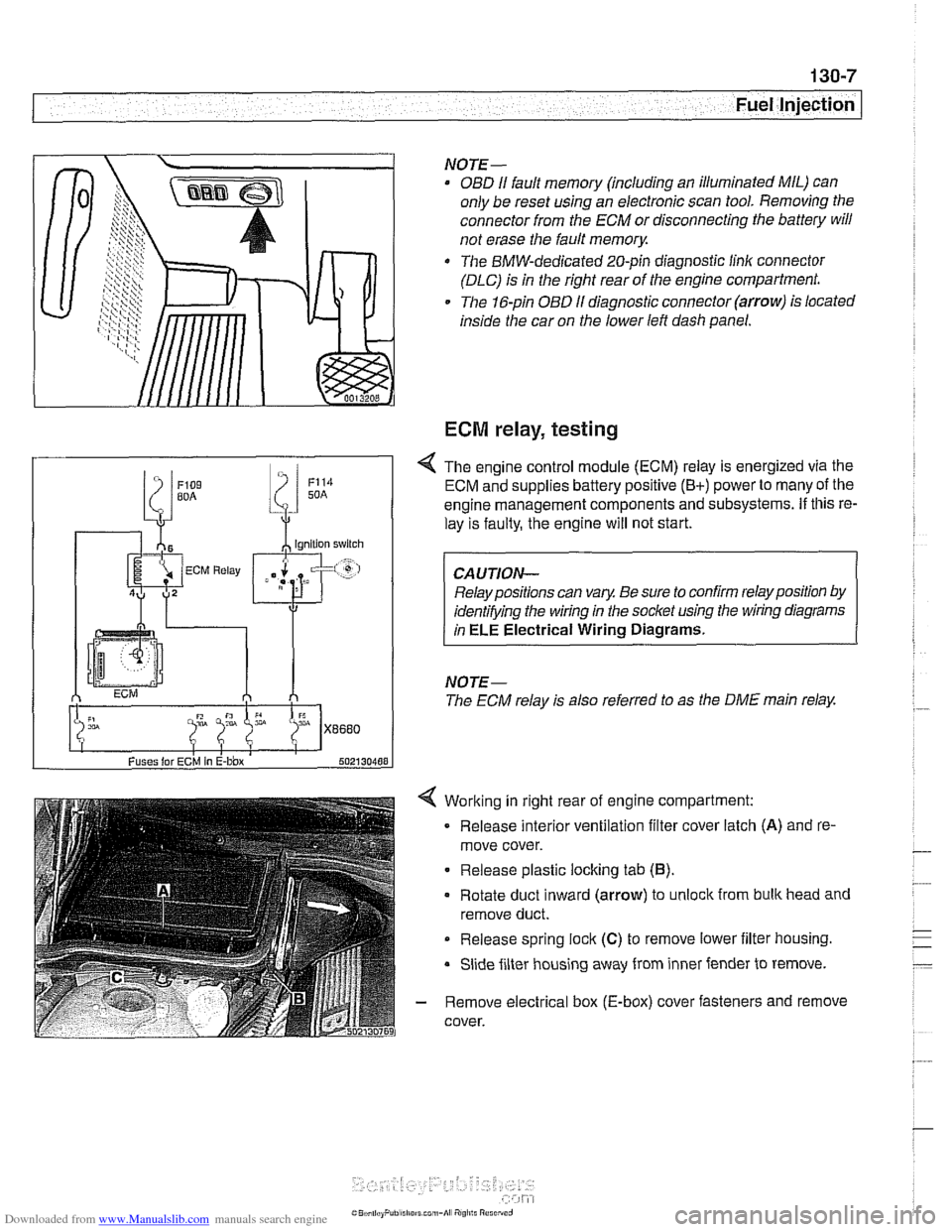
Working in right rear of engine compartment:
Release interior ventilation filter cover latch
(A) and re-
move cover.
Release plastic locking tab
(6).
Rotate duct inward (arrow) to unlock from bulk head and
remove duct.
Release spring
lock (C) to remove lower iilter housing.
Slide filter housing away from inner fender to remove.
- Remove electrical box (E-box) cover fasteners and remove
cover.
NOTE-
OBD I1 fault memory (including an illuminated MIL) can
only be reset using an electronic scan tool. Removing the
connector from the ECM or disconnecting the battery will
not erase the fault
memory.
The BMW-dedicated 20-pin diagnostic linlc connector
(DLC) is in the right rear of the engine compartment.
The 16-pin OBD
I1 diagnostic connector (arrow) is located
inside the car on the lower left dash panel.
ECM relay, testing
Fuses lor ECM In E-bbx 502130488
4 The engine control module (ECM) relay is energized via the
ECM and supplies battery positive
(B+) power to many of the
engine management components and subsystems.
If this re-
lay is faulty, the engine will not start.
Relay positions can vary. Be sure to confirm relay position by
identifying the wiring in the socket using the wiring diagrams
in
ELE Electrical Wiring Diagrams.
NOTE-
The ECM relay is also referred to as the DME main relay.