Wir BMW 540i 1997 E39 Repair Manual
[x] Cancel search | Manufacturer: BMW, Model Year: 1997, Model line: 540i, Model: BMW 540i 1997 E39Pages: 1002
Page 355 of 1002
Downloaded from www.Manualslib.com manuals search engine
120-7
Ignition System
Spark plug electrode gap /Too small /TOO big
Table
b. Ignition secondary voltage diagnostics
Secondary
voltage low
Fuel air mixture
I I Too lean
Secondary
voltage high
Spark plug electrode
Worniburnt
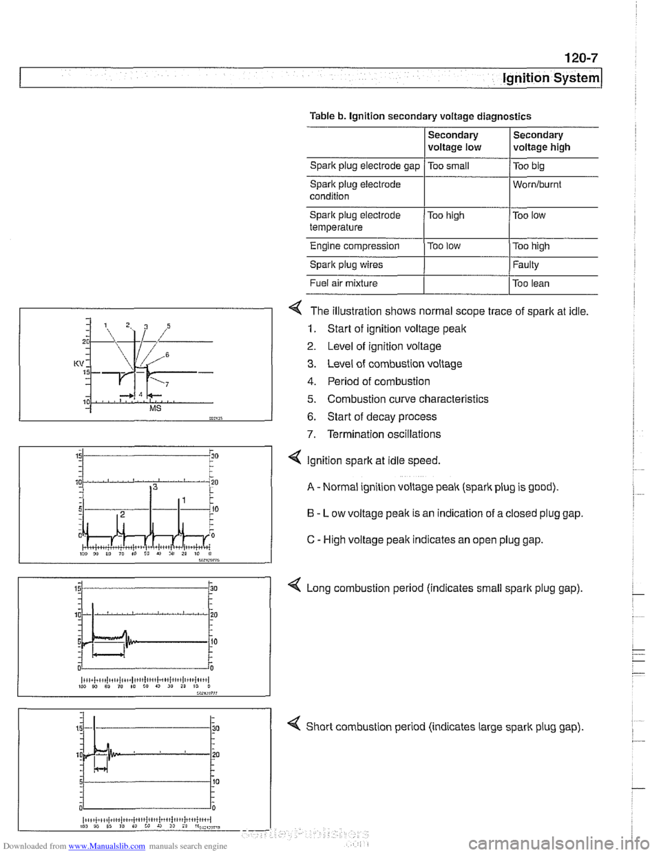
4 The illustration shows normal scope trace of spark at idle.
1. Start of ignition voltage peak
2 Level of ignition voltage
3. Level of combustion voltage
4. Period of combustion
5. Combustion curve characteristics
6. Start of decay process
7. Termination oscillations
Spark plug electrode
temperature
Engine compression
Spark plug wires
4 Short combustion period (indicates large spark plug gap).
Too
high
Too
low
I"" 9, 10 I" to I!, r) i" 21 10 il bW,rn?7G
Too low
Too high
Faulty
4 Ignition spark at idle speed.
A - Normal ignition voltage peak (spark plug is good).
B - Low voltage peak is an indication of a closed plug gap.
C
- High voltage peak indicates an open plug gap.
< Long combustion period (indicates small spark plug gap).
~i,+i!,~,i~tiii~iit~~,t1!lc,',l~~4~l~,~,l,~+~{+',,l 1W W Sl ,@ 10 :o 9 20 21 10 0
Page 356 of 1002
Downloaded from www.Manualslib.com manuals search engine
I lgnition System
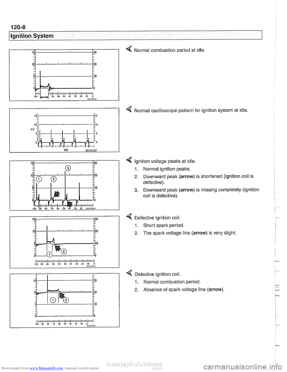
4 Normal combustion period at idle.
4 Normal oscilloscope pattern for ignition system at idle.
15. 15
4 lgnition voltage peaks at idle.
1. Normal ignition peaks.
2. Downward peak (arrow) is shortened (ignition coil is
defective).
3. Downward peak (arrow) is missing completely (ignition
coil is defective).
4 Defective ignition coil.
1. Short spark period.
2. The spark voltage line (arrow) is very slight
< Defective ignition coil.
1. Normal combustion period.
2. Absence of spark voltage line (arrow).
(r+~+~+~(.~i+~/.~~itlt~~(tit~lii~~jt~~~i~ittiii~l IW 10 ED 10 (0 ID U 10 11 70 0 sa,ma,
2 . 15 - .
5 - - - 0
30
.
.
20 .
I0 - -
0
iiiCi;kiW*huiMwiritil~tiii 110 10 00 ro w M A, 30 2" *:,:mu
Page 359 of 1002
Downloaded from www.Manualslib.com manuals search engine
Ignition System
- Turn ignition on and check for battery voltage,
If battery voltage is not present,
checlt wire between termi-
nal
15 and the unloader relay. See ELE Electrical Wiring
Diagrams.
- Turn ignition off.
Remove coil and inspect coil housing for hairline
cracks or
leaking casting material. Replace any
cracked or leaking coil.
NOTE-
A leaky coil may indicate a faulty Engine Control Module
(ECM). Check ECM before installing a new coil.
CAUTION-
Note location of coilground straps before coil removal; rein-
stall in the same location.
Use a multimeter to test:
Coil primary resistance at coil terminals.
Sparlt plug connector resistance.
* Compare results to specification in Table c. lgnition coil
resistance.
Table c. Ignition coil resistance
Coil secondary
resistance
Spark plug connector:
Bosch 1 .O I( ohm t 20%
1.8 ir ohm t 20%
Component
Co~l prlmary
resistance
- Replace ignition coil or sparlt plug connector if resistance
readings do not meet specifications.
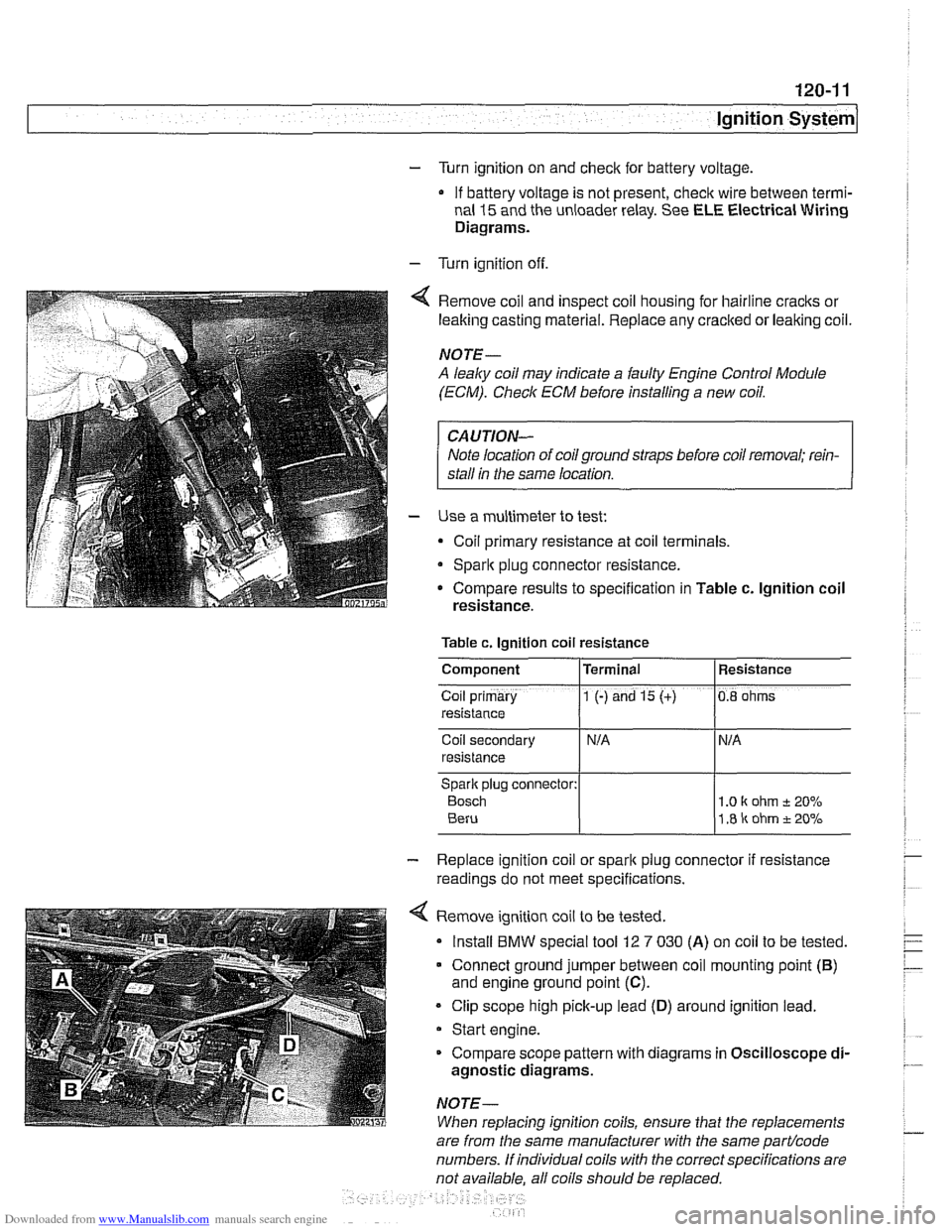
4 Remove ignition coil to be tested.
Install
BMW special tool 12 7 030 (A) on coil to be tested.
Connect ground jumper between coil mounting point
(B)
and engine ground point (C).
Clip scope high pick-up lead (D) around ignition lead.
Start engine.
Compare scope pattern with diagrams in Oscilloscope
di-
agnostic diagrams.
NOTE-
When replacing ignition coils, ensure that the replacements
Terminal
1 (-) and 15 (+)
are
from the same manufacturer with the same partlcode
numbers. If individual coils with the correct specifications are
not available. all coils should be
re~laced.
Resistance
0.8 ohms
Page 360 of 1002
Downloaded from www.Manualslib.com manuals search engine
120-1 2
ignition System
Crankshaftspeedsensor
Crankshaft speed sensor, replacing (M52, M52 TU and
M54 engines)
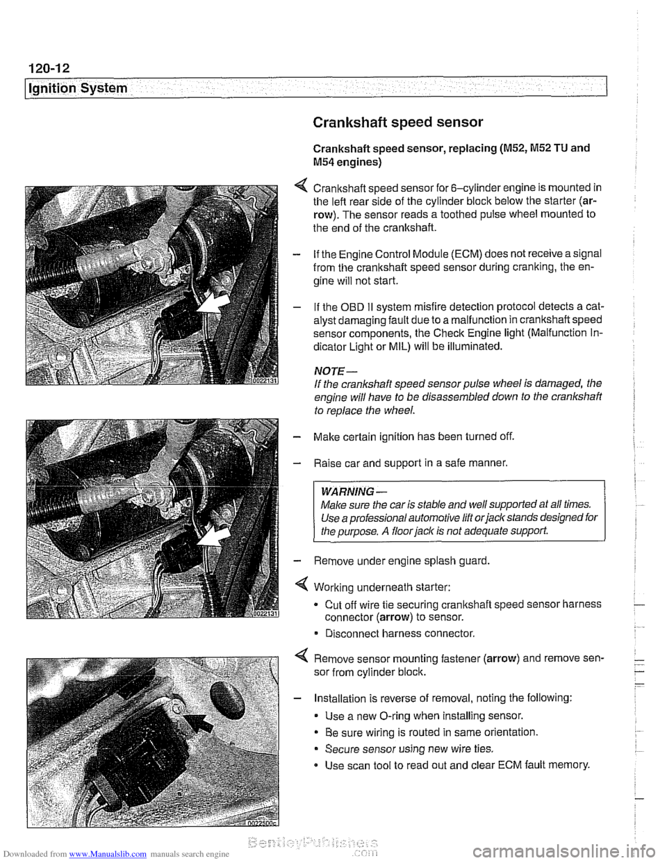
4 Crankshaft speed sensor for 6-cylinder engine is mounted in
the left rear side of the cylinder block below the starter (ar-
row). The sensor reads a toothed pulse wheel mounted to
the end of the crankshaft.
- if the Engine Control Module (ECM) does not receive a signal
from the crankshaft speed sensor during cranking, the en-
gine will not start.
- If the OBD II svstem misfire detection ~rotocol detects a cat- - - ~~
alysr oarnagin; faLlt oJe to a ma I-nclion in crandshafi speeo
sensor components. Ine Check Engine
lignr (Malfuncrion In-
dicator Light or MIL) will be illuminated.
NOTE-
If the crankshaft speed sensor pulse wheel is damaged, the
engine will have to be disassembled down to the crankshaft
to
reolace the wheel.
- Make certain ignition has been turned off.
- Raise car and support in a safe manner.
WARNING -
Make sure the car is stable and well supported at all times.
Use a professional automotive lift orjacltstands designed for
the ouroose.
A floor iaclc is not adequate support.
- Remove under engine splash guard
4 Working underneath starter:
Cut off wire tie securing crankshaft speed sensor harness
connector (arrow) to sensor.
* Disconnect harness connector.
4 Remove sensor mounting fastener (arrow) and remove sen-
sor from cylinder block.
- Installation is reverse of removal, noting the following:
Use a new O-ring when installing sensor.
Be sure wiring is routed in same orientation.
Secure sensor using new wire ties.
Use scan tool to read out and clear ECM fault memory.
Page 362 of 1002
Downloaded from www.Manualslib.com manuals search engine
I Ignition System
Camshaft position sensors
The camshaft position sensors are used by the englne man-
agement system for VANOS control, sequential fuel injection
and knock control.
Intake camshaft position sensor, replacing
(M52,M52 TU
and M54 engines)
- Make certain ignition has been turned off.
- Remove plastic cover from above fuel injectors by prying off
bolt covers and removing cover mounting bolts.
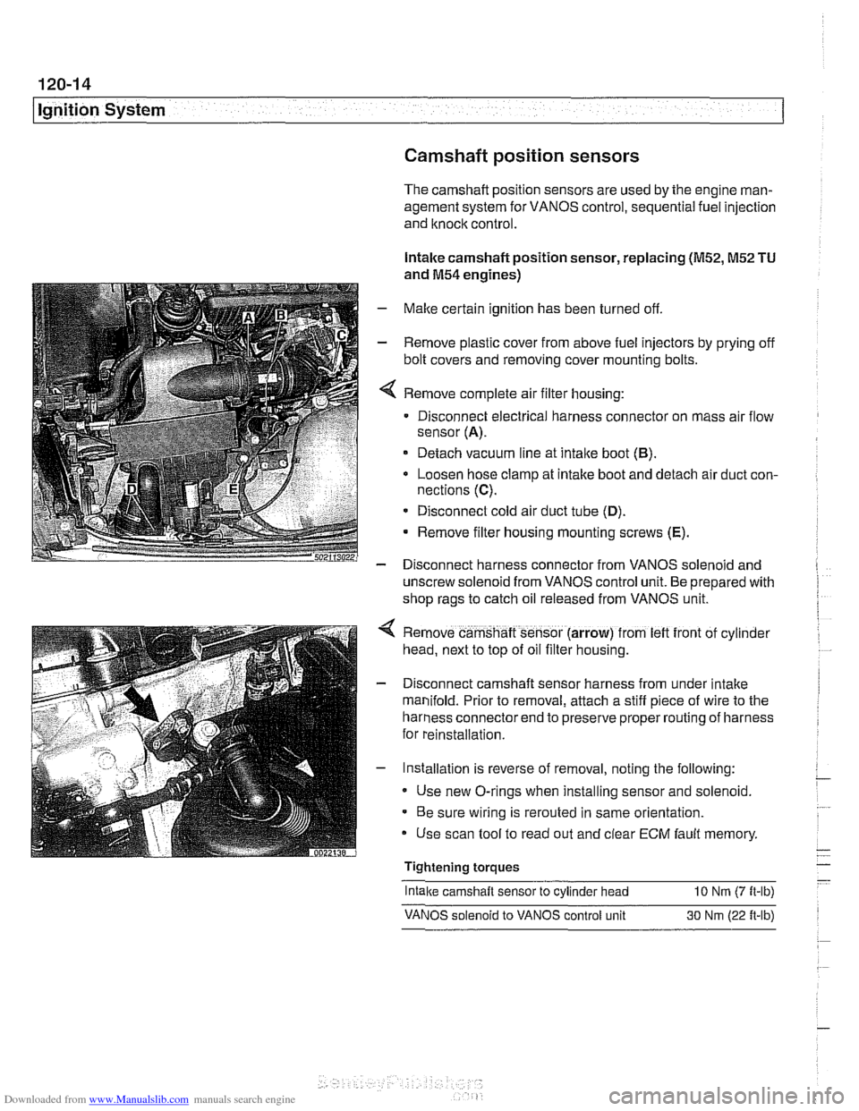
Remove complete air filter housing:
Disconnect electrical harness connector on mass air flow
sensor
(A).
Detach vacuum line at intake boot (B).
Loosen hose clamp at intake boot and detach air duct con-
nections
(C).
* Disconnect cold air duct tube (D).
Remove filter housing mounting screws (E).
- Disconnect harness connector from VANOS solenoid and
unscrew solenoid from VANOS control unit. Be prepared with
shop rags to catch oil released from VANOS unit.
Remove camshaft sensor (arrow) from
left front of cyl~nder
head, next to top of oil filter housing.
Disconnect camshaft sensor harness from under intake
manifold. Prior to removal, attach a stiff piece of wire to the
harness connector end to preserve proper routing of harness
for reinstallation.
Installation is reverse of removal, noting the following:
Use new O-rings when installing sensor and solenoid.
Be sure wiring is rerouted in same orientation.
Use scan tool to read out and clear
ECM fault memory
Tightening torques
-
Intake camshaft sensor to cylinder head 10 Nrn (7 ft-lb)
VANOS solenoid to VANOS control unit 30 Nm (22 ft-lb)
Page 364 of 1002
Downloaded from www.Manualslib.com manuals search engine
120-1 6
Ignition System
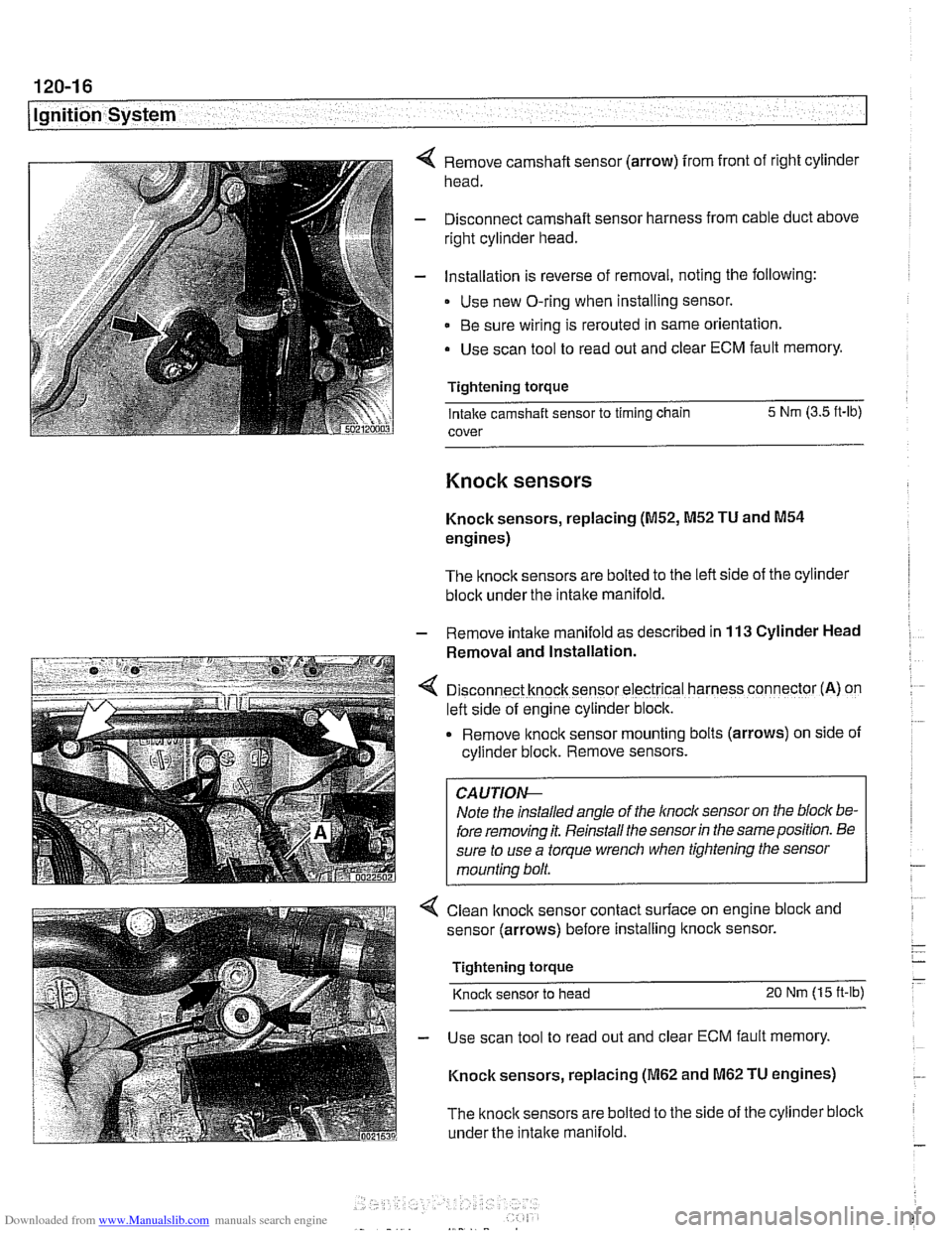
Remove camshaft sensor (arrow) from front of right cylinder
head.
Disconnect camshaft sensor harness from cable duct above
right cylinder head.
Installation is reverse of removal, noting the following:
Use new O-ring when installing sensor.
Be sure wiring is rerouted in same orientation.
Use scan tool to read out and clear ECM fault memory.
Tightening torque Intake camshaft sensor to timing chain 5 Nm
(3.5 ft-lb)
cover
Knock sensors
Knock sensors, replacing (M52, M52 TU and M54
engines)
The knock sensors are bolted to the left side of the cylinder
block under the intake manifold.
- Remove intalte manifold as described in 113 Cylinder Head
Removal and Installation.
D~sconnect knock sensor electrical harness connector (A) on
left side of engine cylinder block.
Remove knock sensor
mount~ng bolts (arrows) on side of
cyllnder block. Remove sensors.
Note the installed angle of the
lnocl~ sensor on the bloc/( be-
fore removing it. Reinstall the sensor
in the same position. Be
sure to use a torque wrench when tightening the sensor
mounting bolt.
< Clean lknock sensor contact surface on engine bloclc and
sensor (arrows) before installing
ltnock sensor.
Tightening torque
Knock sensor to head 20 Nm (15 ft-lb)
- Use scan tool to read out and clear ECM fault memory.
Knock sensors, replacing
(M62 and M62 TU engines)
The
knock sensors are bolted to the side of the cylinder block
under the
intake manifold.
Page 368 of 1002
Downloaded from www.Manualslib.com manuals search engine
- -
Battery, Starter, Alternator
This section covers the battery, alternator, starter and associ-
ated components of the electrical system.
Troubleshooting information
forthese components isfound in
Table a. Battery, alternator and starter troubleshooting.
For additional electrical troubleshooting information, see
600 Electrical System-General.
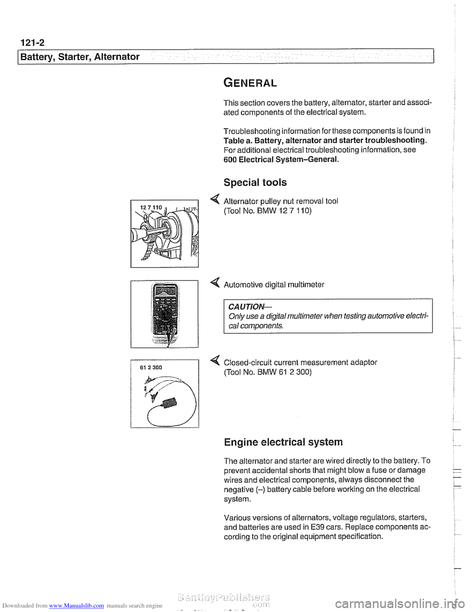
Special tools
4 Automotive digital multimeter
CAUTION-
Only use a digital multirneter when testing automotive electri- I) cal components.
4 Closed-circuit current measurement adaptor
(Tool No.
BMW 61 2 300)
Engine electrical system
The alternator and starter are wired directly to the battery. To
prevent accidental shorts that might blow a fuse or damage
wires and electrical components, always disconnect the
negative
(-) battery cable before working on the electrical
system.
Various versions of alternators, voltage regulators, starters,
and batteries are used in
E39 cars. Replace components ac-
cording to the original equipment specification.
Page 370 of 1002
Downloaded from www.Manualslib.com manuals search engine
.-. .
Battery, Starter, Alternator
Warnings and cautions
WARNING -
Wear goggles, rubber gloves, and a rubber apron when
working around the battery or battery acid (electrolyte).
Battery acid contains sulfuric acid and can cause skin
irritation and burning.
If acid is spilled on your skin or
clothing, flush the area at once with large quantities of
water. If electrolyte gets into your eyes, flush them with
large quantities of clean water for several minutes and
call a physician.
Batteries that are being charged or are fully charged
give off explosive hydrogen gas. Keep sparks and open
flames away. Do not
smoke.
CA UTIOI\C
Only use a digital multimeter when testing automotive elec-
trical components.
. If a repair procedure specifies disconnecting the bat-
tery, follow the instruction for safety reasons.
Prior to disconnecting the battery, read the battery dis-
connection cautions in
001 General Cautions and
Warnings.
Models with MS43 engine management: Allow at least
3 minutes to elapse after turning ignition ley to OFFpo-
sition before disconnecting battery. This willallow sum-
cient tinie to complete the DMJL (fuel tank pressure)
test
* Disconnecting the battery cables may erase fault codes
stored in ECM memory.
Always disconnect the negative
(-) battery cable first
and reconnect it last. Cover the battery post with an in-
sulating material whenever the cable is removed.
Do not disconnect battery, alternator or starter wires
while the engine is running.
0 Never reverse the battery cables. Even a momentary
wrong connection can damage the alternator or other
electrical components.
Do not depend on the color of insulation to tell battery
positive and negative cables apart. Label cables before
removing.
The slide-tilt sunroof may fail to function properly
after
disconnecting and reconnecting the battery. Reinitial-
ize sunroof as described in 540 Sunroof.
Page 379 of 1002
Downloaded from www.Manualslib.com manuals search engine
Battery, Starter, ~lternatorl
Charging system quick-check
Use a digital multimeter to measure voltage across the bat-
tery terminals with key off and then again with engine running.
Battery voltage should be about 12.6 volts with key off and be-
tween 13.5 and 14.5 volts with engine running.
NOTE-
The regulated voltage (engine running) should be between
13.2 and 14.5, depending on temperature andoperating con-
ditions.
If the voltage is higher than 14.8, the voltage regula-
tor or
mulitfunction controller is most likely faulty
Check for clean and tight battery cables. Check ground cable
running from negative
(-) battery terminal to chassis and
ground cable running from engine to chassis. Check alterna-
tor drive belt condition and tension.
Charging system, checking
CAUTIOI\C
* Do not disconnect the battery while the engine is running.
Damage to the alternator and/or engine electronic systems
may result.
Only use a digital multimeter when testing charging
system components.
--7
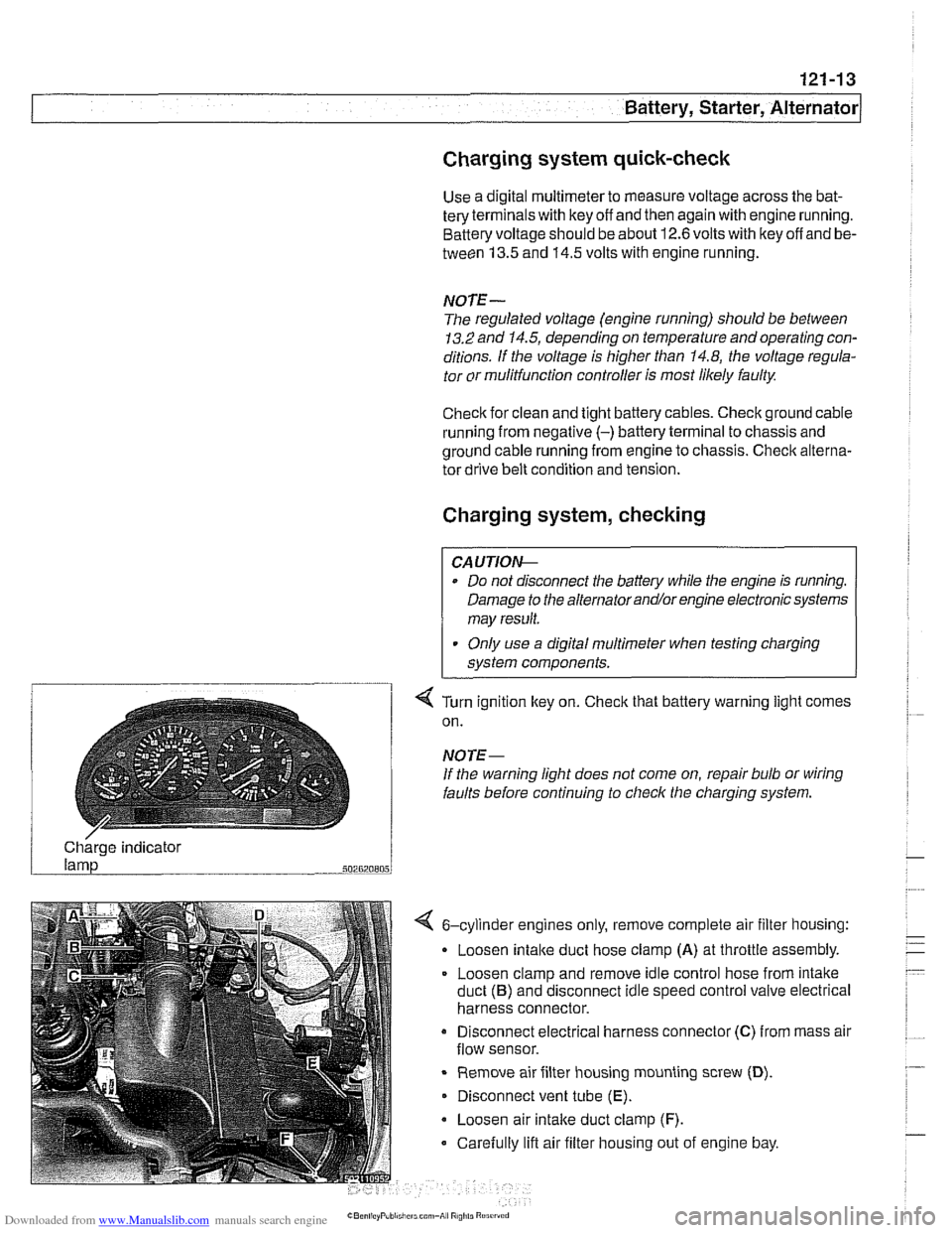
4 Turn ignition key on. Check that battery warning light comes
on.
NOTE-
If the warning light does not come on, repair bulb or wiring
faults before continuing to checlc the charging system.
/ Charge indicator
502820805
4 6-cylinder engines only, remove complete air filter housing:
Loosen
intake duct hose clamp (A) at throttle assembly.
Loosen clamp and remove idle control hose from intake
duct
(B) and disconnect idle speed control valve electrical
harness connector.
Disconnect electrical harness connector
(C) from mass air
flow sensor.
Remove air filter housing mounting screw
(D).
Disconnect vent tube (E).
Loosen air intake duct clamp (F).
Carefully lift air filter housing out of engine bay.
Page 380 of 1002
Downloaded from www.Manualslib.com manuals search engine
- -
/Battery, Starter, Alternator -- - -. - --I
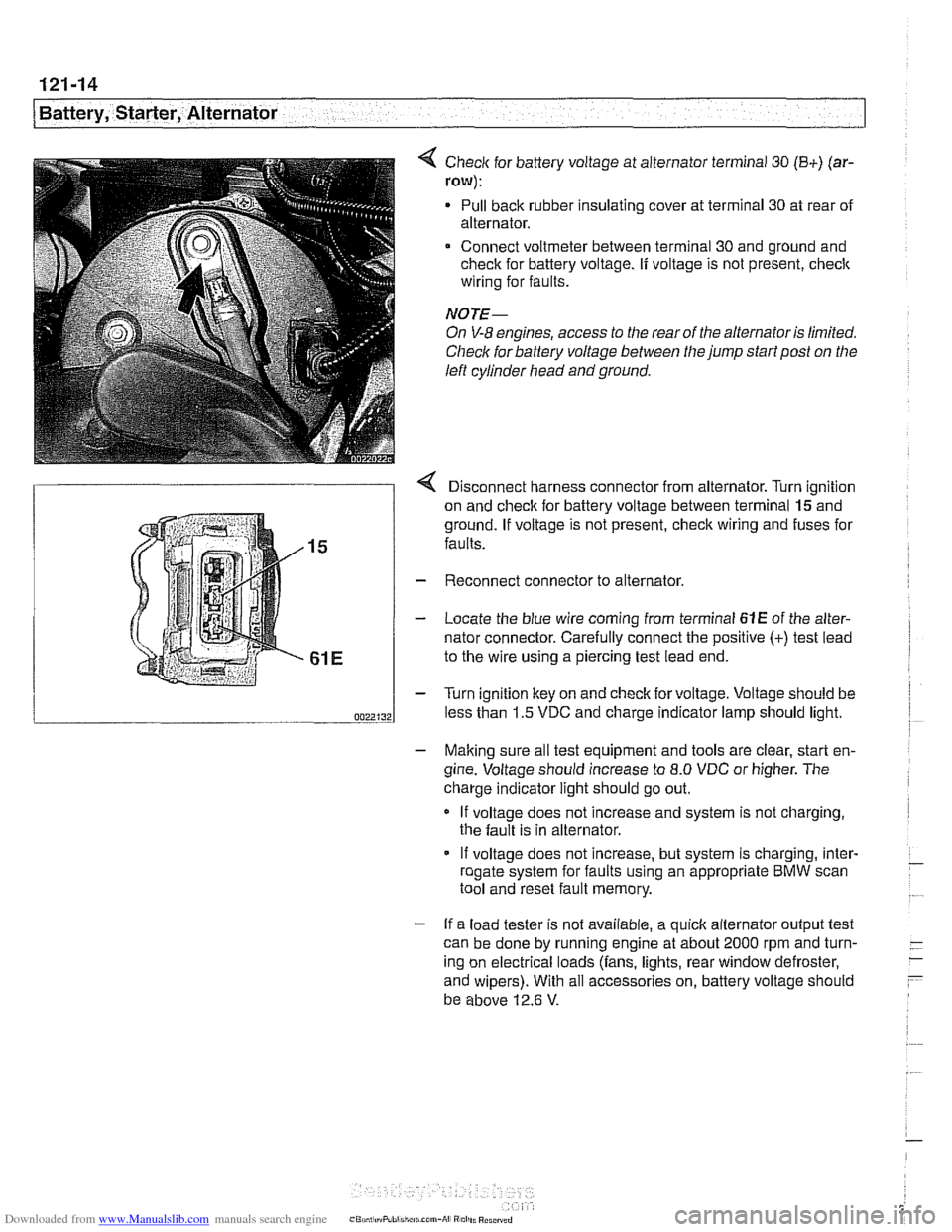
< Check for battery voltage at alternator terminal 30 (B+) (ar-
row):
Pull back rubber insulating cover at terminal 30 at rear of
alternator.
Connect voltmeter between terminal 30 and ground and
check for battery voltage.
If voltage is not present, check
wiring for faults.
NOTE-
On V-8 engines, access to the rear of the alternator is limited.
Check for battery voltage between the jump start post on the
left cylinder head and ground.
r Disconnect harness connector from alternator. Turn ianition
on and check for battery voltage between terminal
lgand
ground. If voltage is not present, check wiring and fuses for
faults.
Reconnect connector to alternator.
Locate the blue wire coming from terminal
61E of the alter-
nator connector. Carefully connect the positive
(+) test lead
to the wire using a piercing test lead end.
Turn ignition key on and check for voltage. Voltage should be
less than 1.5 VDC and charge indicator lamp should light.
- Making sure all test equipment and tools are clear, start en-
gine. Voltage should increase to
8.0 VDC or higher. The
charge indicator light should go out.
If voltage does not increase and system is not charging,
the fault is in alternator.
- If voltage does not increase, but system is charging, inter- - roaate svstem for faults usina an appropriate BMW scan - .. . tool and'reset fault memory.
- If a load tester is not available, a quick alternator output test
can be done by running engine at about 2000 rpm and turn-
- -
ing on electrical loads (fans, lights, rear window defroster, -
- and wipers). With all accessories on, battery voltage should
be above 12.6
V.