Wir BMW 540i 1997 E39 Owners Manual
[x] Cancel search | Manufacturer: BMW, Model Year: 1997, Model line: 540i, Model: BMW 540i 1997 E39Pages: 1002
Page 424 of 1002
Downloaded from www.Manualslib.com manuals search engine
/Fuel Injection
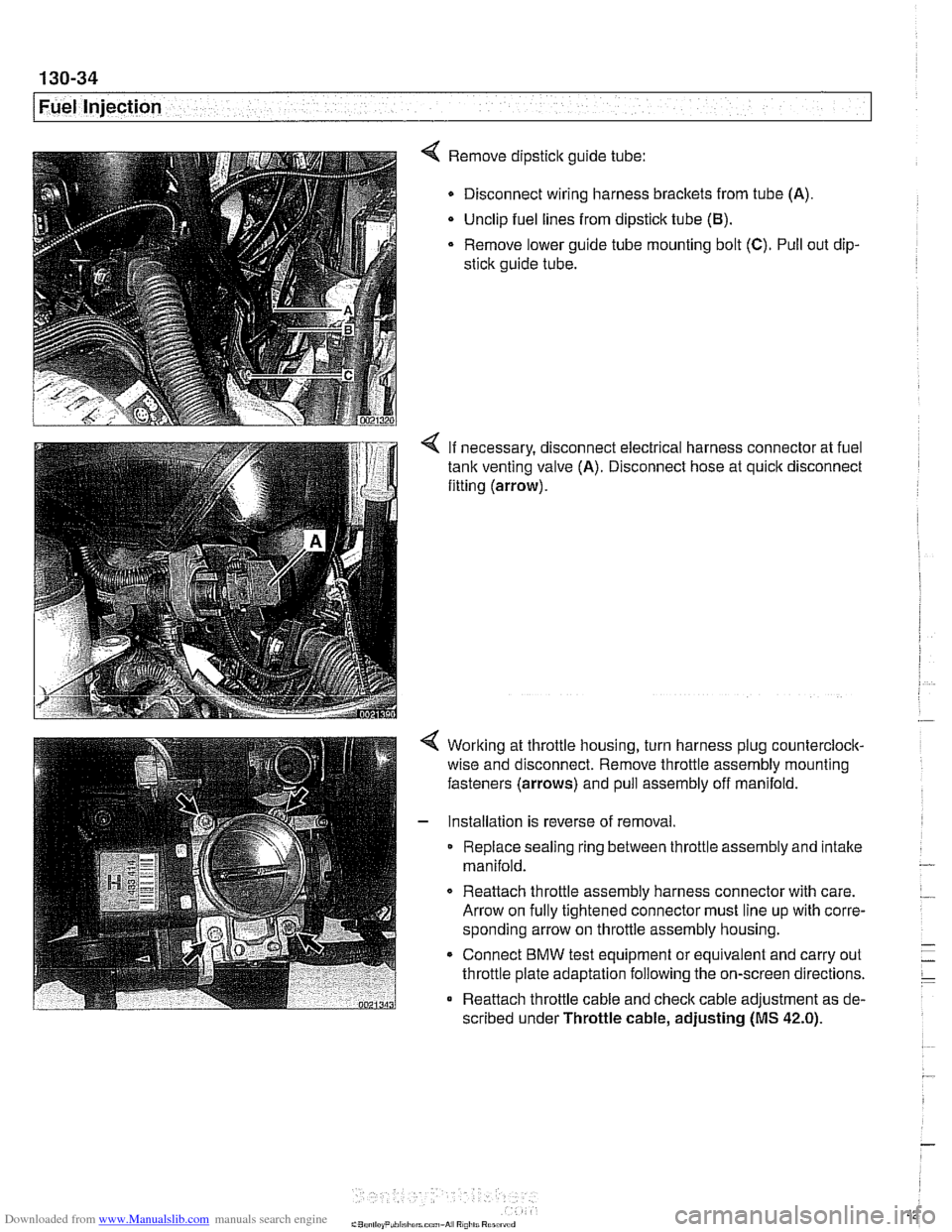
4 Remove dipstick guide tube:
Disconnect wiring harness brackets from tube (A).
Unclip fuel lines from dipstick tube
(El).
Remove lower guide tube mounting bolt (C). Pull out dip-
stick guide tube.
< If necessary, disconnect electrical harness connector at fuel
tank venting valve (A). Disconnect hose at quick disconnect
fitting (arrow).
Working at throttle housing, turn harness plug counterclock-
wise and disconnect. Remove throttle assembly mounting
fasteners (arrows) and pull assembly off manifold.
Installation is reverse of removal
Replace sealing ring between throttle assembly and intake
manifold.
0 Reattach throttle assembly harness connector with care.
Arrow on fully tightened connector must line up with corre-
sponding arrow on throttle assembly housing.
* Connect BMW test equipment or equivalent and carry out
throttle plate adaptation following the on-screen directions.
Reattach throttle cable and check cable adjustment as de-
scribed under Throttle cable, adjusting
(MS 42.0).
Page 426 of 1002
Downloaded from www.Manualslib.com manuals search engine
130-36
[~uel Injection
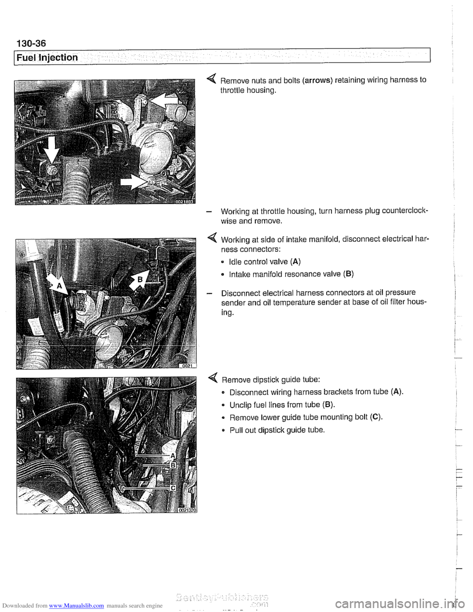
4 Remove nuts and bolts (arrows) retaining wiring harness to
throttle housing.
- Working at throttle housing, turn harness plug countercloclc
wise and remove.
4 Working at side of intake manifold, disconnect electrical bar-
ness connectors:
Idle control valve (A)
Intake manifold resonance valve (B)
- Disconnect electrical harness connectors at oil pressure
sender and oil temperature sender at base of oil filter hous-
ing.
4 Remove dipstick guide tube:
Disconnect wiring harness brackets from tube
(A)
Unclip fuel lines from tube (B).
Remove lower guide tube mounting bolt (C).
Pull out dipstick guide tube.
Page 431 of 1002
Downloaded from www.Manualslib.com manuals search engine
. -
Fuel Injection I
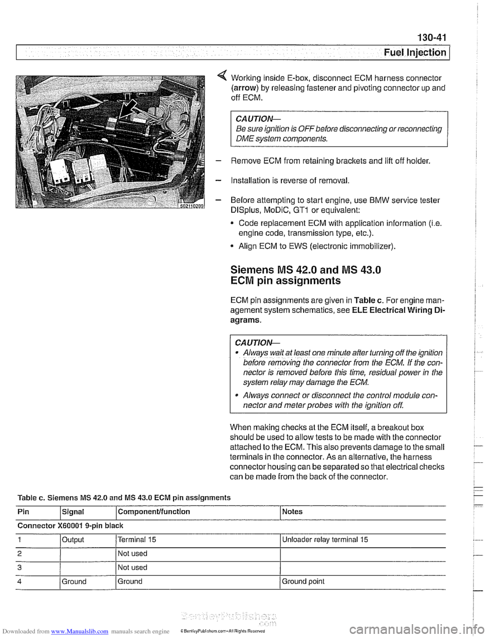
Working inside E-box, disconnect ECM harness connector
(arrow) by releasing fastener and pivoting connector up and
off ECM.
CA UTIOW
Be sure ignition is OFF before disconnecting or reconnecting
DME system components.
Remove ECM from retaining brackets and lift off holder.
Installation is reverse of removal
Before attempting to start engine, use
BMW service tester
DISplus, MoDiC, GTl or equivalent:
* Code replacement ECM with application information (i.e
engine code, transmission type, etc.).
Align ECM to EWS (electronic immobilizer).
Siemens MS 42.0 and MS 43.0
ECM pin assignments
ECM pin assignments are given in Table c. For engine man-
agement system schematics, see
ELE Electrical Wiring Di-
agrams.
/ CAUTIOW I
Al~ays wait at least one mfnule after turning off the ignition
before
remov;ng [he connecror irom rhe ECM. If the con-
nector is removed before this time, residual power
in the
system relay may damage the
ECM.
Always connect or disconnect the control module con-
nector and meter probes with the ignition off.
When making checks at the ECM itself, a
breakout box
should be used to allow tests to be made with the connector
attached to the ECM. This also prevents damage to the small
terminals in the connector. As an alternative, the harness
connector housing can be separated so that electrical checks
can be made from the back of the connector.
Table
c. Siemens MS 42.0 and MS 43.0 ECM pin assignments
Pin
lslgnal l~om~onentlfunction 1 Notes
Connector
X60001 9-pin black
1 loutput I~erminai 15 I Unloeder relay terminal 15
2 I 1 Not used I
3 Not used
4 Ground
Ground Ground
point
Page 436 of 1002
Downloaded from www.Manualslib.com manuals search engine
130-46
Fuel Injection
When system faults are detected, a diagnostic trouble code
(DTC) is stored in the engine control module (ECM). The MIL
also illuminates if an emissions-related fault is detected.
When faults arise, or
if the malfunction indicator lamp (MIL) is
illuminated, begin troubleshooting by connecting BMW ser-
vice tester
DISplus. MoDiC, GTI or equivalent scan tool. The
capabilities of
OED II software has the potential to save hours
of diagnostic time and to help avoid incorrect component re-
placement and possible damage to system components.
CA UTIOiU-
The tests in this section may set fault codes (DTCs) in the
ECM and illuminate the MIL. After ail testing is completed,
access and clear DTC fault
memory using an OED I/ or
BMW compatible scan tool. See OBD On-Board Diag-
nostics.
Only use a digital
multimeter for electrical tests.
Relay positions can vary. Be sure to confirm relay
posi-
. tion by identifying the wiring in the socket using the wir-
ing diagrams-found in ~~~~lectrical Wiring
Diagrams.
NOTE-
OED I1 fault memory (including an illuminated MIL) can
only be reset
using~the special scan tool. Removing the
connector from the ECM or disconnecting the battery will
not erase the fault
memory.
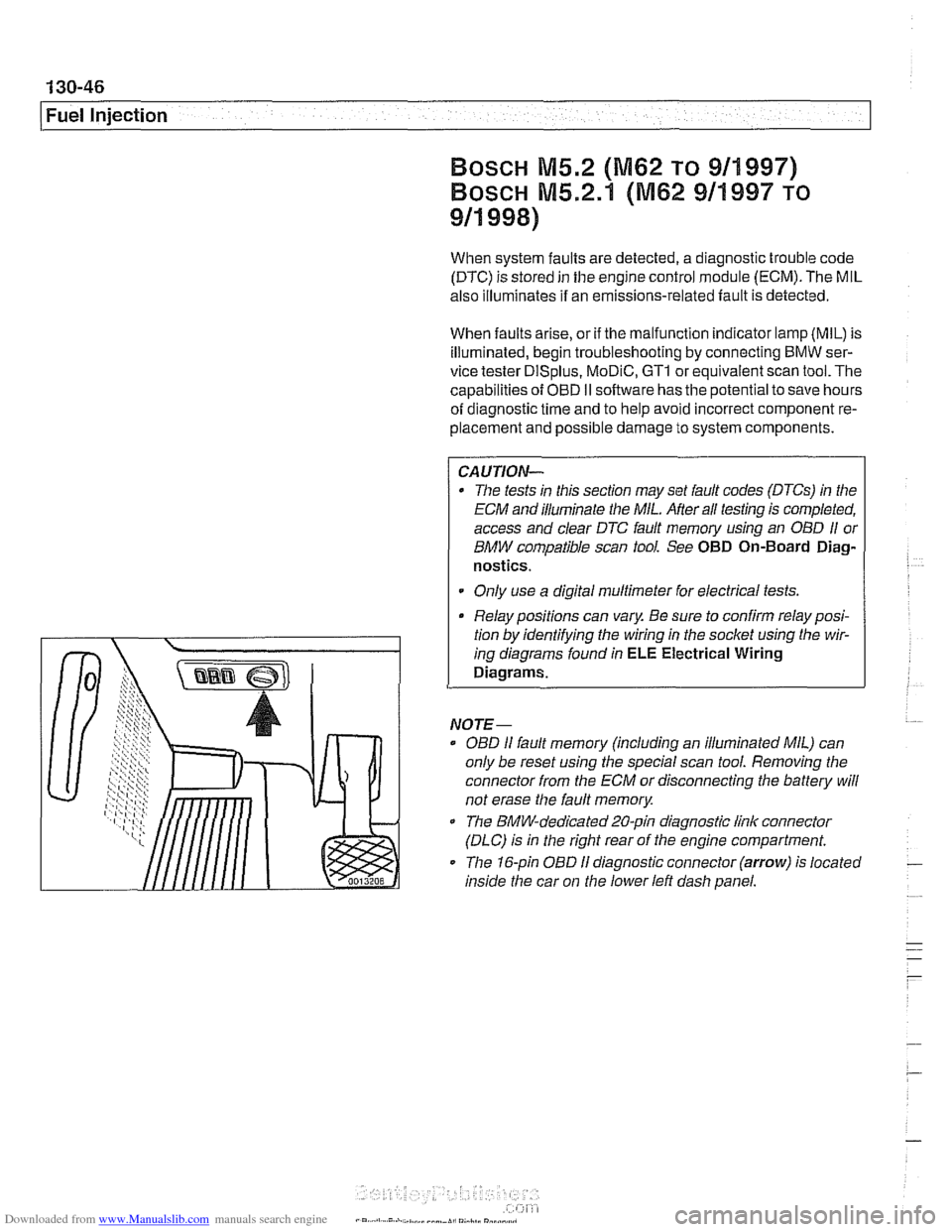
The BMW-dedicated 20-pin diagnostic link connector
(DLC) is in the right rear of the engine compartment.
The 16-pin OBD
I1 diagnostic connector (arrow) is located
inside the car on
the lower left dash panel.
Page 439 of 1002
Downloaded from www.Manualslib.com manuals search engine
- Fuel Injection
ECM relay, testing
The engine control module (ECM) relay is energized via the
ECM and supplies battery positive
(B+) power to many of the
engine
management components and subsystems. If this re-
lay is faulty, the engine will not start.
CAUTIOI\C
Relay positions can vary. Be sure to confirm relay position by
identifying the wiring
in the socket using the wiring diagrams
in ELE Electrical Wiring Diagrams.
NOTE-
The ECM relay is also referred to as the DME main relay.
ECM relay powers:
* ECM
Ignition coils
Fuel injection
Evaporative leak detection pump
(5.2.1 only)
Idle air actuator
Camshaft sensors Evaporative emissions valve
Hot film mass air flow sensor
Fuel pump relay
Oxygen sensor heaters
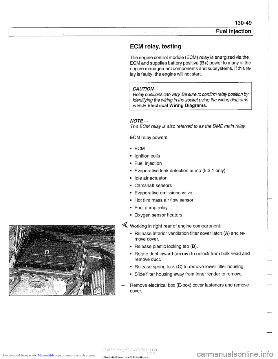
4 Working in right rear of engine compartment:
Release interior ventilation filter cover latch
(A) and re-
move cover.
Release plastic locking tab
(B).
Rotate duct inward (arrow) to unloclc from bulk head and
remove duct.
0 Release spring lock (C) to remove lower filter housing.
Slide filter housing away from inner fender to remove.
- Remove electrical box (E-box) cover fasteners and remove
cover.
Page 440 of 1002

Downloaded from www.Manualslib.com manuals search engine
130-50
Fuel Injection
Bosch M5.2
ECM relay
1 HoL al ail iirnel XOL a1 ail limes
i--[-----i F109 (BOA) electronics I L.$.....: .I:
ECM relay . . . . . . . . . ,
8,s
:,
6 1 .. ... ~~.~~. . ...... .-, Engine control ii~~-~.~~..~ ........ ~~~~~~.~~~~:. module relay -;I
Of?
,c,;,,,
< With ignition off, remove ECM relay (arrow) in electronics
box (E-box) at right rear of engine compartment.
NOTE-
Relay locations can vary. Conh relay identification by
matcliing wiring colors and terminal numbers.
4 Check for voltage at terminal 6 of main relay socket (30-red
wire). On M5.2 cars also check for battery voltage at terminal
8.
. . . . . . . . . ,
If battery voltage is present, continue testing
.
If battery voltage is not present, check large red wire(s) in
relay socltet. See
ELE Electrical Wiring Diagrams.
%P,,tt
- Reinstall relay and turn ignition on. Gain access to underside
of relay socket and
checlc for ground at terminal 4 (85-brown
wire).
. . . . . . . . . . . . - - - - - - - - - . - - - . . l ,,-. ; Engine i f .: , ; Fuse carrier .,A . :engine /;is? /control L.!.!! .... 1.: ...... !.::..! I lij :module electronics If
ground is present, continue testing
If ground is not present, signal from ECM is missing. Checic
wire between ECM and relay.
4 With ignition on and relay installed, check for battery voltage
at terminal
2 (87-redlwhite wire). On M5.2.1 cars also checlc
for battery voltage at terminal 5.
If battery voltage is present, relay has energized and is
functioning correctly.
If battery voltage is not present and all earlier tests are OK,
relay is faulty and should be replaced.
Page 441 of 1002
Downloaded from www.Manualslib.com manuals search engine
130-51
Fuel Injection
Oxygen sensors, checking
The oxygen sensor provides an input voltage signal [0.2 vdc
(lean) to 0.8 vdc (rich)] to the
ECM based on the oxygen con-
tent in the exhaust gas. To generate voltage, the sensor tem-
perature must exceed 575"
F (300" C). Therefore the sensor
is electrically heated.
NO JE -
The test given below is not a conclusive test of oxygen sen-
sor efficiency and does not test how the oxygen sensor re-
acts to changing conditions. Pin numbers and wire colors
can vary Always check the wiring diagrams to confirm wire
color and pin assignment.
0 The oxygen sensorconnectorplugs are locatednext to the
catalytic converters.
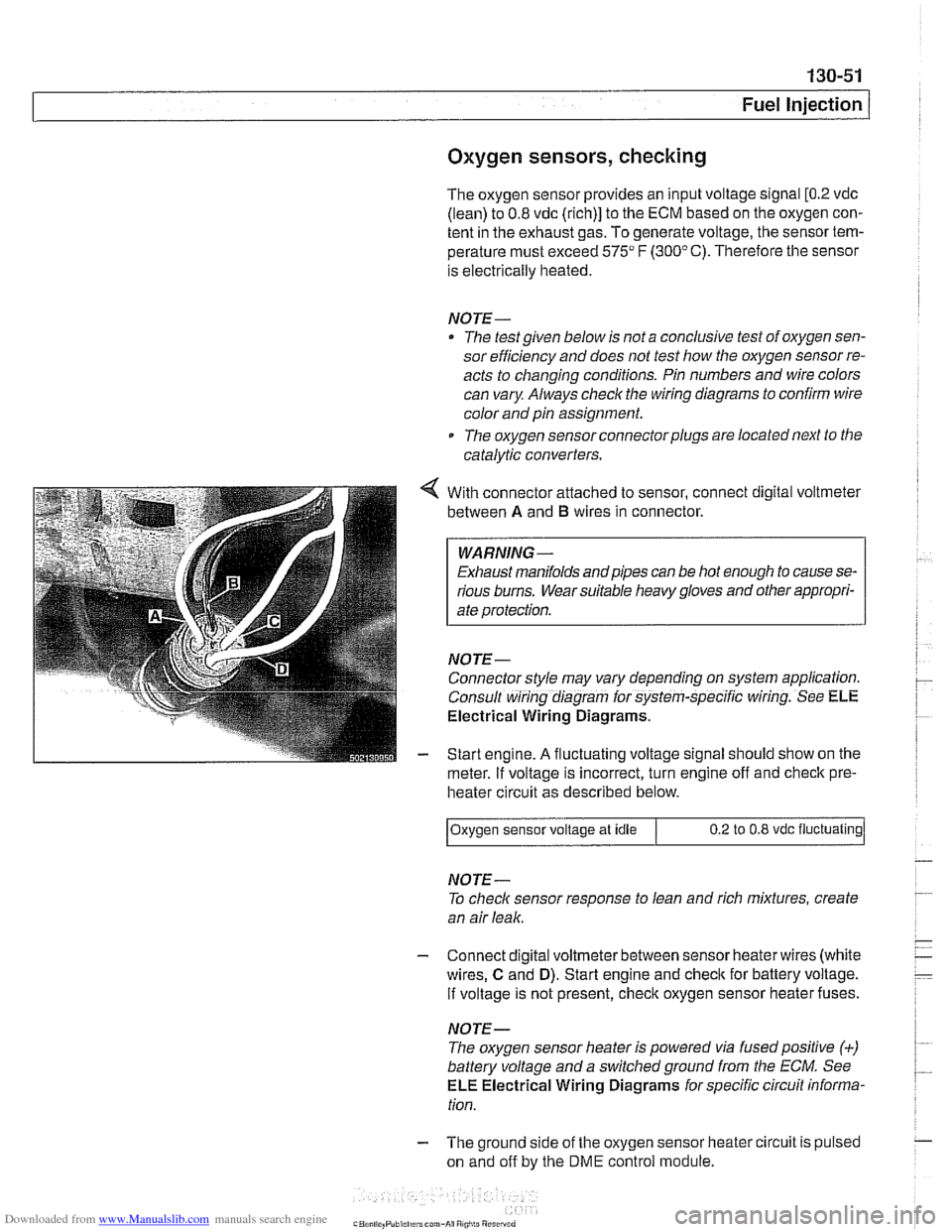
With connector attached to sensor, connect digital voltmeter
between
A and B wires in connector.
WARNING -
Exhaust manifolds andpipes can be hot enough to cause se-
rious burns. Wear suitable heavy gloves and other appropri-
ate protection.
NOJE-
Connector style may vary depending on system application.
Consult wiring diagram for system-specific wiring. See
ELE
Electrical Wiring Diagrams.
Start engine.
A fluctuating voltage signal should show on the
meter.
If voltage is incorrect, turn engine off and check pre-
heater circuit as described below.
NOJE-
To check sensor response to lean and rich mixtures, create
an air leak.
Oxygen sensor
voltage at idle
- Connect digital voltmeterbetween sensor heaterwires (white
wires,
C and D). Start engine and check for battery voltage.
If voltage is not present, check oxygen sensor heater fuses.
0.2 to 0.8 vdc fluctuating
NOJE-
The oxygen sensor heater is powered via fusedpositive (+)
battery voltage and a switchedground from the ECM. See
ELE Electrical Wiring Diagrams for specific circuit informa-
tion.
- The ground side of the oxygen sensor heater circuit is pulsed
on and off by the
DME control module.
Page 442 of 1002
Downloaded from www.Manualslib.com manuals search engine
.. .-
/Fuel lnjeciion
NOJE-
With engine oft disconnect harness connector and checlc
heating element resistance between white wires on the sen-
sor side of harness. If the element is electrically open (no
continuity), replace sensor.
- If oxygen sensor does not produce a fluctuating voltage and
preheater circuit is
OK, replace sensor.
NOJE-
If not already applied, coat oxygen sensor threads w~th anti-
seize compound before installat~on. Do not get the com-
pound on the sensor tip.
Tightening torque Oxygen sensor to exhaust system
55 Nm (41 ft-lb)
Fuel injectors, checking and replacing
The fuel iniectors are switched on and off (oaened and
closed)
by'the ECM. The injectors are connkcted to acom-
mon power source. A ground signal from the ECM is used to
open and close the injectors.
CA U JIOG
Use only a digital multimeter or an LED injector tester when
testing injectors or wiring. Use of an analog
VOM or incan-
descent test light may damaqe the engine controlmodule.
4 Remove fuel rail cover. See 110 Engine Removal and in-
stallation.
With the engine running, place the point of a long screwdriver
on each injector and check for a cliclting vibration.
If no vibra-
tion is found do the voltage
checit shown below.
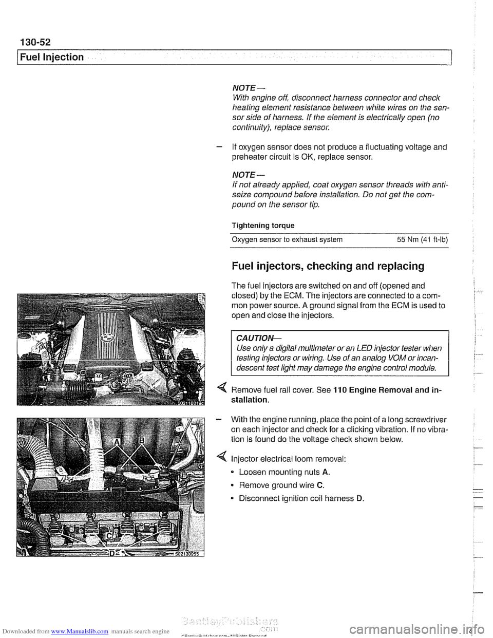
Injector electrical loom removal:
- Loosen mounting nuts A.
Remove ground wire C.
Disconnect ignition coil harness D
Page 444 of 1002
Downloaded from www.Manualslib.com manuals search engine
130-54
I Fuel Injection ldle speed control valve,
testing and replacing
ldle speed is maintained by the ECM through the idle speed
control valve. The idle control function compensates for en-
gine load and engine operating conditions. ldle speed is
adaptive through the ECM and no adjustments can be made.
Before checking valve, confirm that throttle position sensor is
working correctly.
NOTE-
The test given below is an electrical check only. It does not
check the mechanical operation of the valve. If the valve is
sticking, hanging up or is sluggish in operation, substituting a
Inown good valve is the best way to check it.
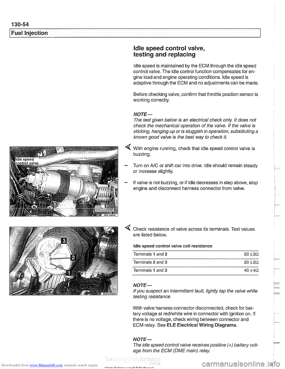
With engine running, check that idle speed control valve is
buzzing.
Turn on
AIC or shift car into drive. ldle should remain steady
or increase slightly.
If valve is not buzzing, or if idle decreases in step above, stop
engine and disconnect harness connector from valve.
4 Check resistance of valve across its terminals. Test values
are listed below.
ldle speed control valve coil resistance
Terminals
1 and 2 20 +2%
Terminals 2 and 3 20 +2Q
Terminals 1 and 3 40 +4%
NOTE-
If you suspect an intermittent fault, lightly tap the valve while
testing resistance.
With valve harness connector disconnected, check for bat-
tery voltage at redlwhite wire in connector with ignition on.
If . ~~ ~~
there is no voltage, check wiring between connector and 7 ECM relay. See ELE Electrical Wiring Diagrams.
NOTE- - The idle speed control valve receivespositive (+) battery volt-
age from the ECM (DME main) relay
Page 445 of 1002
Downloaded from www.Manualslib.com manuals search engine
Fuel Injection
- If voltage is present as described above, check wiring be-
tween ECM and valve. If no wiring faults are found, check
ECM signal to valve.
- When replacing idle speed control valve, clean and inspect
all sealing areas.
. Inspect sealing ring in throttle body and replace if neces-
sary.
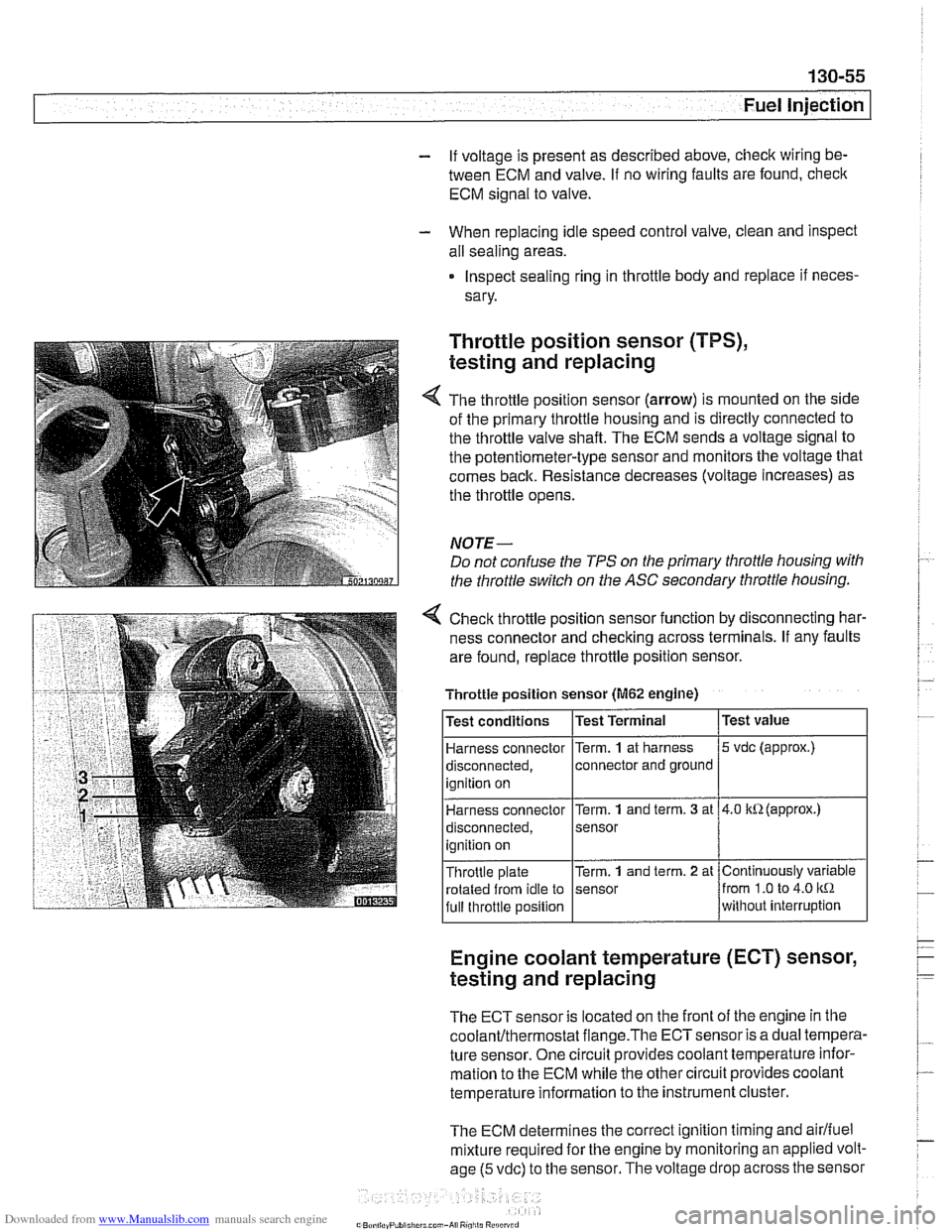
Throttle position sensor (TPS),
testing and replacing
The throttle position sensor (arrow) is mounted on the side
of the primary throttle housing and is directly connected to
the throttle valve shaft. The ECM sends a voltage signal to
the potentiometer-type sensor and monitors the voltage that
comes back. Resistance decreases (voltage increases) as
the throttle opens.
NOTE-
Do not confuse the TPS on the primary throttle housing with
the throttle switch on the
ASC secondary throttle housing.
4 Check throttle position sensor function by disconnecting har-
ness connector and checking across terminals. If any faults
are found, replace throttle position sensor.
Engine coolant temperature (ECT) sensor,
testing and replacing
Throttle position sensor (M62 engine)
The ECT sensor is located on the front of the engine in the
coolanVthermostat flange.The ECTsensor is a dual tempera-
ture sensor. One circuit provides coolant temperature infor-
mation to the ECM while the other circuit provides coolant
temperature information to the instrument cluster.
The ECM determines the correct ignition timing and
airlfuel
mixture required for the engine by monitoring an applied volt-
age
(5 vdc) to the sensor. The voltage drop across the sensor
Test
value
5 vdc (approx.)
4.0 kR(approx.)
Continuously variable
from
1.0 to 4.0 kR
without interruption
Test
conditions
Harness connector
disconnected, ignition on
Harness connector
disconnected,
ignition on
Throttle plate rotated from idle to
full throttle position Test Terminal
Term.
1 at
harness
connector and ground
Term.
1 and term. 3 at
sensor
Term.
1 and term. 2 at
sensor