locking BMW 540i 1998 E39 Workshop Manual
[x] Cancel search | Manufacturer: BMW, Model Year: 1998, Model line: 540i, Model: BMW 540i 1998 E39Pages: 1002
Page 685 of 1002
Downloaded from www.Manualslib.com manuals search engine
L.. Steering and Wheel ~li~nrnentl ~
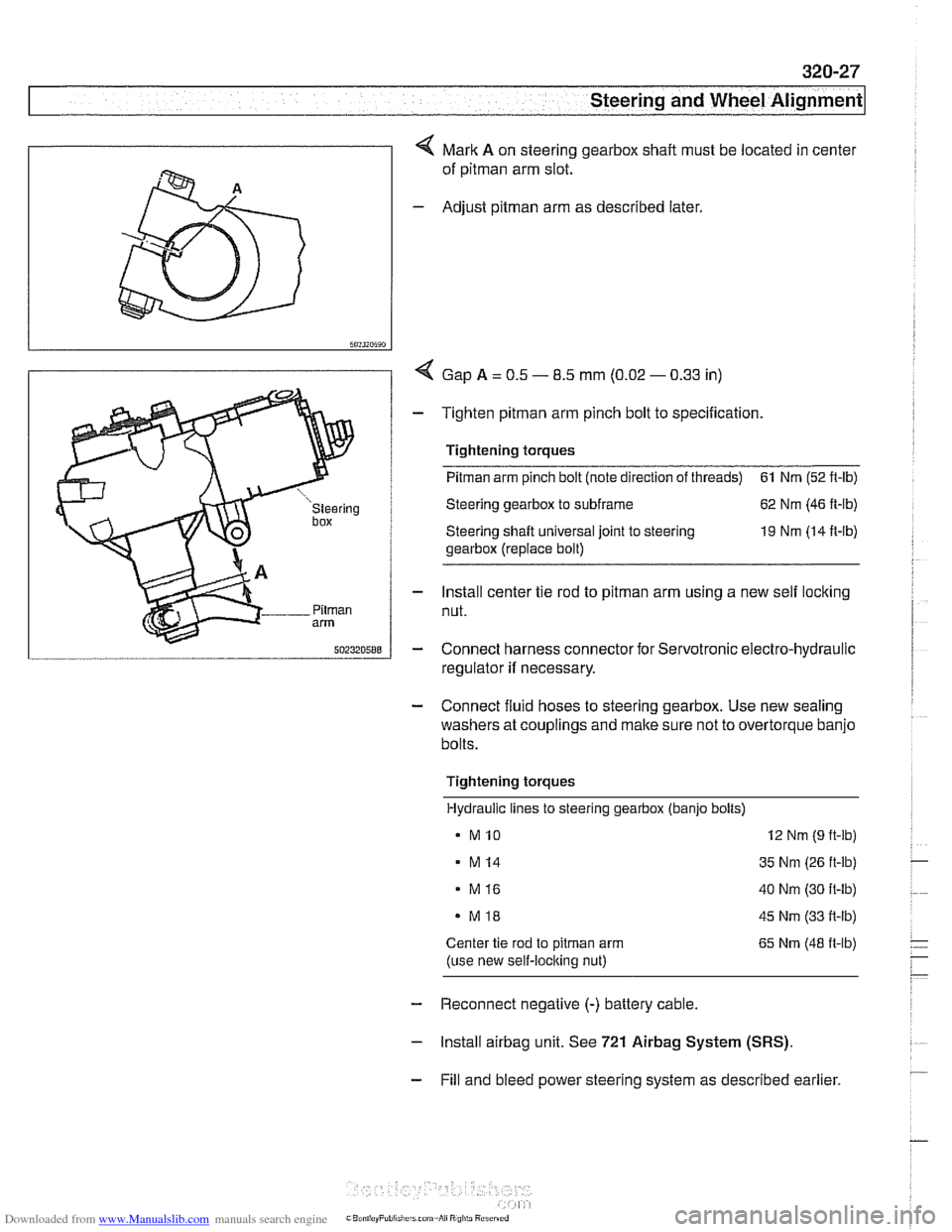
4 Mark A on steering gearbox shaft must be located in center
of
pitman arm slot.
- Adjust pitman arm as described later.
I 5"?~~5~"
I / < Gap A = 0.5 - 8.5 mm (0.02 - 0.33 in)
- Tighten pitman arm pinch bolt to specification.
' 1 Tightening torques
I u "steering Steering gearbox to subframe 62 Nm (46 ft-lb)
box Steering shaft universal joint to steering 19 Nm (14 It-lb)
gearbox (replace bolt)
- Install center tie rod to pitman arm using a new self locking
Pilrnan nut. arm
5nz3zn588 - Connect harness connector for Servotronic electro-hydraulic
regulator
if necessary.
- Connect fluid hoses to steering gearbox. Use new sealing
washers at couplings and make sure not to overtorque banjo
bolts.
Tightening torques Hydraulic lines to steering gearbox (banjo bolts)
MI0 12 Nm (9 ft-lb)
- M14 35 Nm (26 ft-lb)
. M16 40 Nm (30 ft-lb)
MI8 45 Nm (33 it-lb)
Center tie rod to pitrnan arm 65 Nm (48 it-lb)
(use new self-loclting nut)
- Reconnect negative (-) battery cable.
- lnstall airbag unit. See 721 Airbag System (SRS).
- Fill and bleed power steering system as described earlier.
Page 686 of 1002
Downloaded from www.Manualslib.com manuals search engine
320-28
[steering and Wheel Alignment
Pitman arm, removing and installing
- Raise front of car. Remove splash shield from under engine.
Male sure the car is
firmly supported on jack stands de-
signed for the purpose. Place jack stands beneath structural
chassis points. Do not place
jaclc stands under suspension
parts.
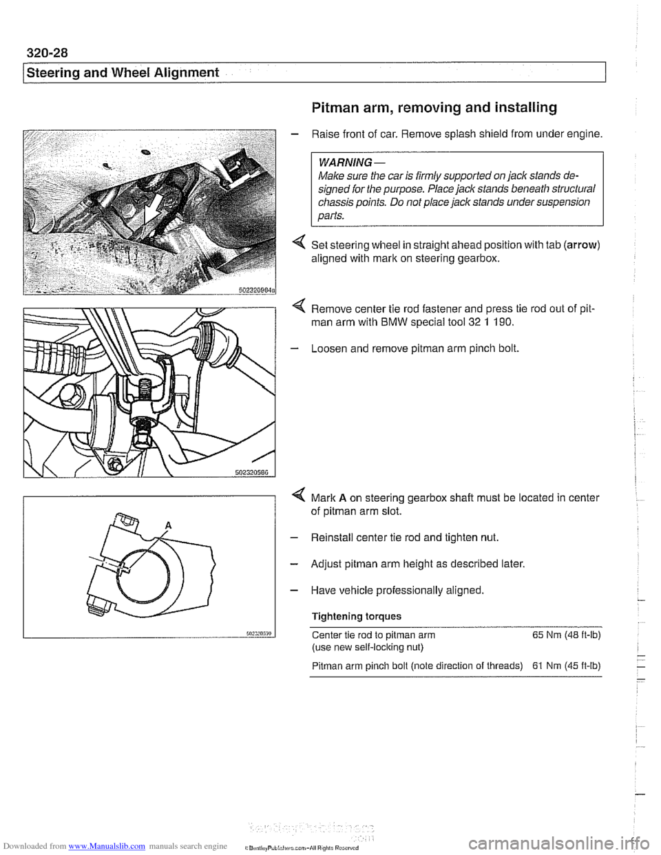
4 Set steering wheel in straight ahead position with tab (arrow)
aligned with mark on steering gearbox.
Remove center tie rod fastener and press tie rod out of pit.
man arm with BMW special
too1 32 1 190.
- Loosen and remove pitman arm pinch bolt
4 Mark A on steering gearbox shalt must be located in center
of
pitman arm slot.
- Reinstall center tie rod and tighten nut.
- Adjust pitman arm height as described later.
- Have vehicle professionally aligned.
Tightening torques
50:s,n5m Center tie rod to pitman arm 65
Nm (48 ft-lb)
(use new self-locking nut)
Pitman arm pinch bolt (note direction of threads) 61 Nrn (45 ft-lb)
Page 688 of 1002
Downloaded from www.Manualslib.com manuals search engine
I Steering and Wheel Alignment
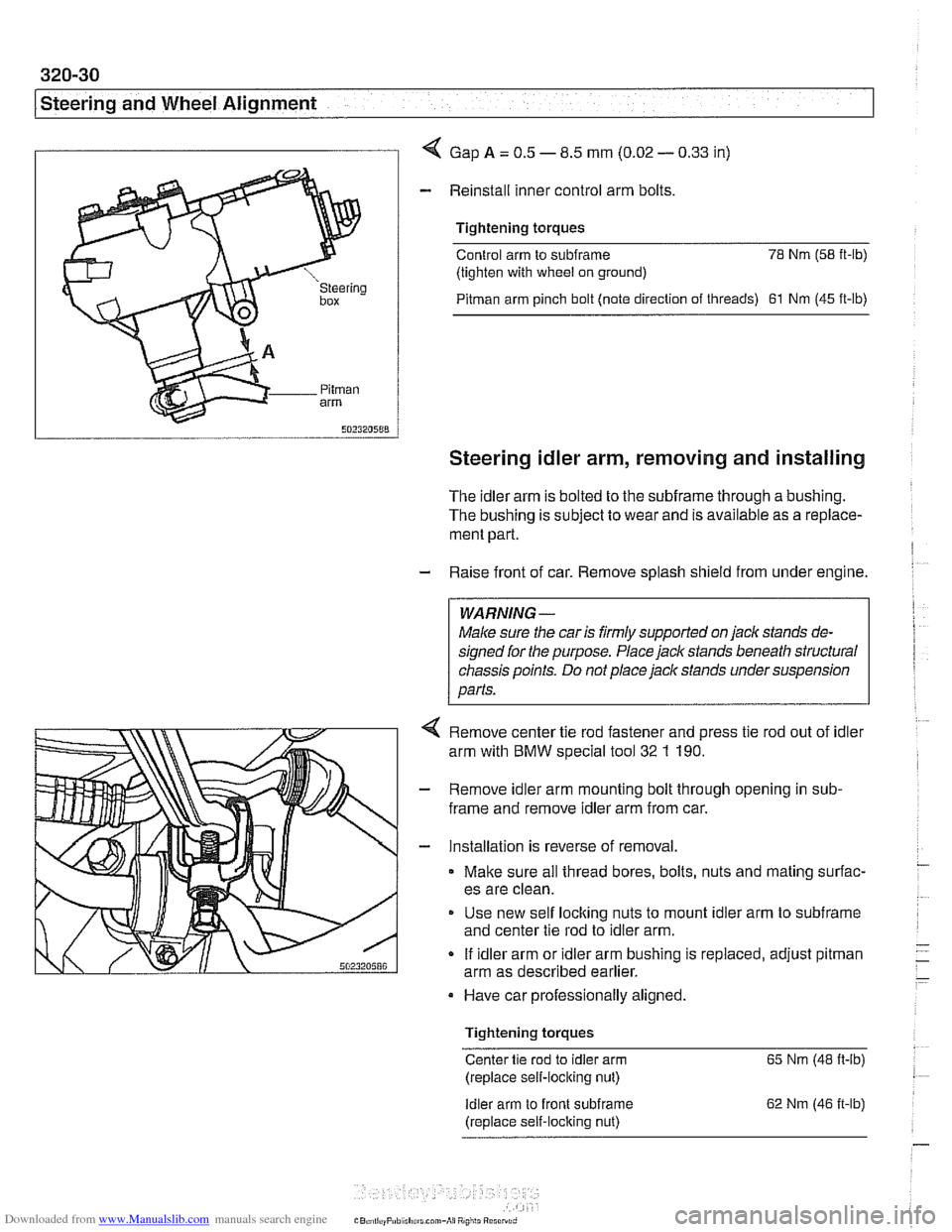
I I 4 Gap A = 0.5 - 8.5 mm (0.02 - 0.33 in)
- Reinstall inner control arm bolts
Tightening torques
Control arm to
subframe 78 Nm (58 it-lb)
(tighten with wheel on ground)
Pitman arm pinch bolt (note direction of threads) 61 Nm (45 ft-lb)
Steering idler arm, removing and installing
The idler arm is bolted to the subframe through a bushing.
The bushing is subject to wear and is available as a replace-
ment part.
- Raise front of car. Remove splash shield from under engine.
WARNING -
Male sure the car is firmly supported on jaclc stands de-
signed for the purpose. Place jack stands beneath structural
chassis points. Do not place jack stands under suspension
parts.
4 Remove center tie rod fastener and press tie rod out of idler
arm with
BMW special tool 32 1 190.
- Remove idler arm mounting bolt through opening in sub-
frame and remove idler arm from car.
- Installation is reverse of removal.
Make sure all thread bores, bolts, nuts and mating surfac-
es are clean.
Use new self
loclting nuts to mount idler arm to subframe
and center tie rod to idler arm.
If idler arm or idler arm bushing is replaced, adjust
pitman
arm as described earlier.
Have car professionally aligned.
Tightening torques
Center tie rod to idler arm 65 Nm (48 ft-ib)
(replace self-locking nut)
Idler arm to front subirame
(replace self-locking nut) 62
Nm (46 it-lb)
Page 689 of 1002
Downloaded from www.Manualslib.com manuals search engine
320-31
Steering and Wheel ~li~nrnentl
ldler arm bushing, replacing
- Remove idler arm as described earlier.
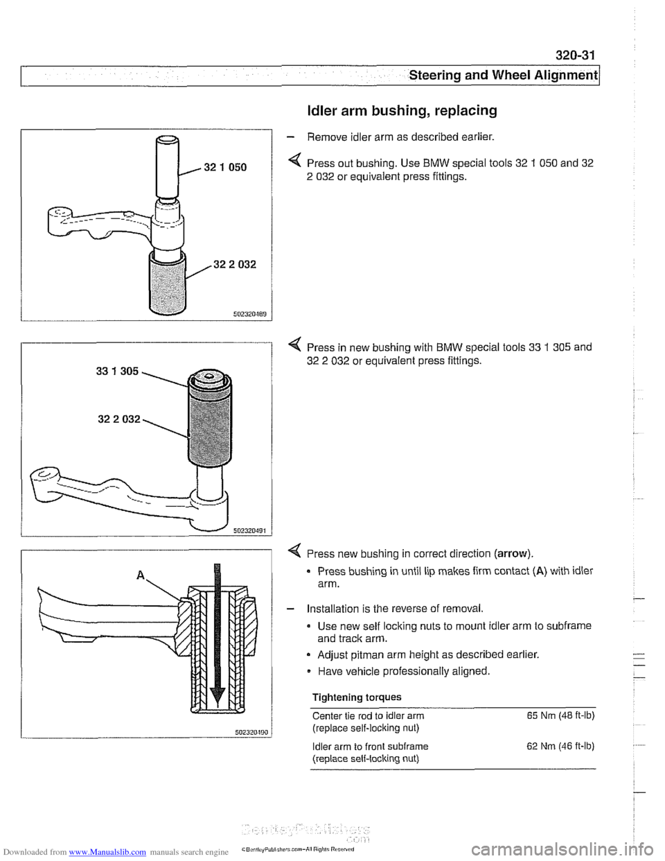
< Press out bushing. Use BMW special tools 32 1 050 and 32
2 032 or equivalent press fittings.
4 Press in new bushing with BMW special tools 33 1 305 and
32 2 032 or equivalent press fittings.
4 Press new bushing in correct direction (arrow).
u ..... "A",
Press bushing in until lip makes firm contact (A) with idler
arm.
I
Installation is the reverse of removal
Use new self locking nuts to mount idler arm to
subframe
and traclc arm.
a Adjust pitman arm height as described earlier.
Have vehicle professionally aligned.
Tightening torques Center tie rod to idler arm
65 Nm (48 ft-lb)
;nl?mmn / (replace self-locking nut)
ldler arm to front
subframe
(replace sell-locking nut) 62
Nm (46 ft-lb)
Page 690 of 1002
Downloaded from www.Manualslib.com manuals search engine
320-32
Steering and Wheel Alignment
Center tie
rod, replacing
- Raise front of car. Remove splash shield from under engine.
WARNING-
Make sure tlie car is firmly supported on jack stands de-
signed for the purpose. Place jack stands beneath structural
cliassis points. Do not place jack stands under suspension
parts.
- Measure length of left and right (outer) tie rods. Write down
measurements.
NOTE-
Accurate measurement of the tie rod end with reference to
the center tie rod will help approximate correct wheel align-
ment when new parts are installed.
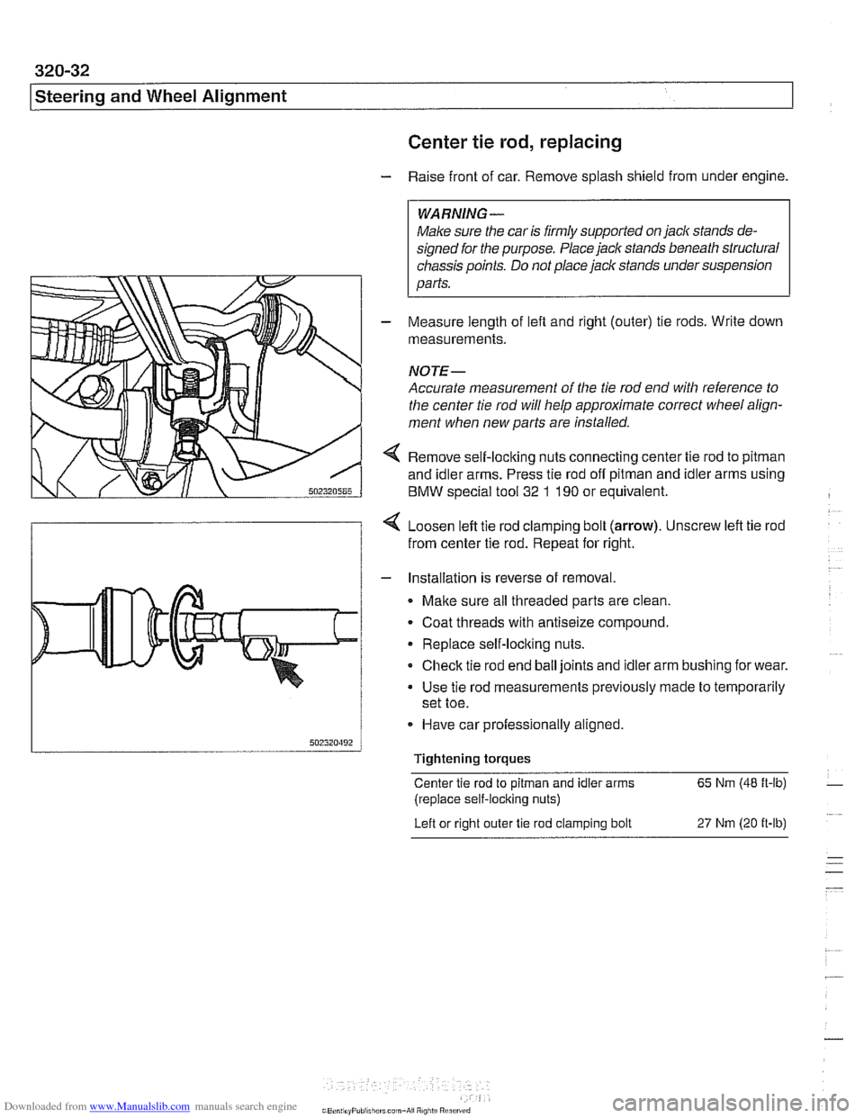
4 Remove self-loclting nuts connecting center tie rod to pitman
and idler arms. Press tie rod off pitman and idler arms using
BMW special tool
32 1 190 or equivalent.
4 Loosen left tie rod clamping bolt (arrow). Unscrew left tie rod
from center tie rod. Repeat for right.
- Installation is reverse of removal.
Malte sure all threaded parts are clean.
. Coat threads with antiseize compound.
Replace self-loclting nuts.
Check tie rod end ball joints and idler arm bushing for wear.
Use tie rod measurements previously made to temporarily
set toe.
- Have car professionally aligned.
Tightening torques
Center tie rod to
pitman and idler arms 65 Nm (48 ft-lb)
(replace self-locking nuts)
Left or right outer
tie rod clamping bolt 27 Nm (20 it-lb)
Page 703 of 1002
Downloaded from www.Manualslib.com manuals search engine
Rear ~us~ensionl
Rear strut assembly, disassembling and
assembling
Replace struts and coil springs in pairs only
Replacing the upper strut mount, spring or strut requires that
the strut assembly first be removed from the car, as described
earlier. Strut disassembly requires a spring compressor.
WARNING-
Do not attempt to disassemble the strut without a spring com-
pressor designed specifically for the job.
- Remove strut assembly from car as described in Rear strut
assembly, removing
bnd installing
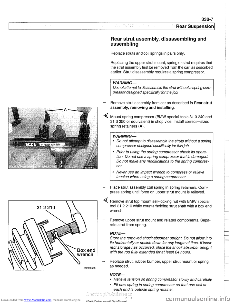
4 Mount spring compressor (BMW special tools 31 3 340 and
31 3 350 or equivalent) in shop vice. Install correct-sized
spring retainers
(A).
WARNING-
Do not attempt to disassemble the struts without a spring
compressor designed specifically for this job.
* Prior to using the spring compressor checlc its opera-
tion. Do not use a spring compressor that is damaged.
Do not make any modifications to the spring compres-
sor.
Never use an impact wrench to compress or relieve
tension when using a spring compressor.
1
- Place strut assembly coil spring in spring retainers. Com-
press spring until force on upper strut mount is relieved.
Remove strut top mount self-locking nut with BMW special
tool
31 2 21 0 while counterholding strut shaft with a box end
wrench.
- Remove upper strut mount and related components. Sepa-
rate strut from spring.
NOTE-
Store the removed shock absorber upright Do not allow it to
lie horizontally or upside down for any length of time. If incor-
rect storage has occurred, place the
shoclc absorber upright
with the rod
fully extended for at least 24 hours.
- Replace strut, rubber bumper, upper strut mount or spring,
as needed.
NOTE- Relieve tension on spring compressor slowly and carefully.
Fit new spring in spring compressor so that one coil at
each end is outside spring retainer.
Page 704 of 1002
Downloaded from www.Manualslib.com manuals search engine
330-8
Rear Suspension
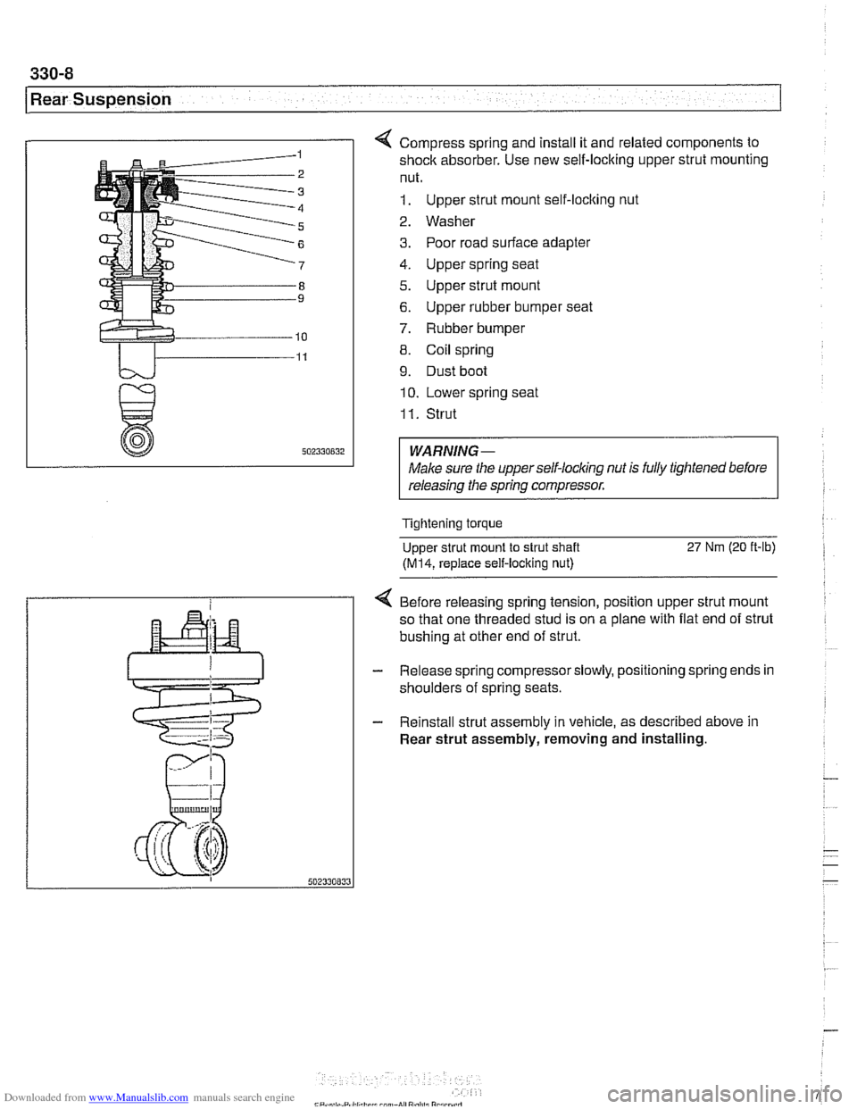
4 Compress spring and install it and related components to
shock absorber. Use new self-locking upper strut mounting
nut.
1. Upper strut mount self-locking nut
2. Washer
3. Poor road surface adapter
4. Upper spring seat
5. Upper strut mount
6. Upper rubber bumper seat
7. Rubber bumper
8. Coil spring
9. Dust boot
10. Lower spring seat
I I. Strut
WARNING-
Male sure the upperself-locking nut is fully tightened before
releasing the spring compressor.
Tightening torque
Upper strut mount to strut shaft
27 Nm (20 ft-lb)
(M14, replace self-locking nut)
4 Before releasing spring tension, position upper strut mount
so that one threaded stud is on a plane with flat end of strut
bushing at other end of strut.
- Release spring compressorslowly, positioning spring ends in
shoulders of spring seats.
- Reinstall strut assembly in vehicle, as described above in
Rear strut assembly, removing and installing.
Page 706 of 1002
Downloaded from www.Manualslib.com manuals search engine
330-1 0
/Rear Suspension
- Remove rubber protective cap from shock absorber upper
mount.
- Remove shock absorber upper mounting nuts.
- Remove shock absorber lower mounting bolt. Lower shock
absorber out of wheel housing.
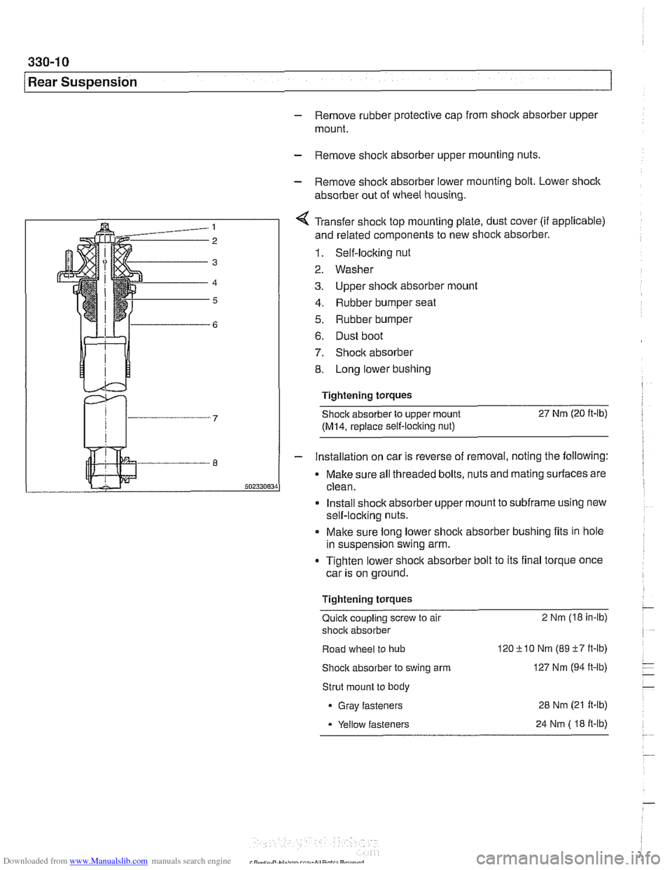
< Transfer shock top mounting plate, dust cover (if applicable)
and related components to new shoclc absorber.
1. Self-locking nut
2. Washer
3. Upper siioclc absorber mount
4. Rubber bumper seat
5. Rubber bumper
6. Dust boot
7. Shock absorber
8. Long lower bushing
Tightening torques
Shock absorber to upper mount
27 Nm (20 it-lb)
(M14, replace self-locking nut)
- Installation on car is reverse of removal, noting the following:
Make sure all threaded bolts, nuts and mating surfaces are
clean.
Install shock absorber upper mount to
subframe using new
self-locking nuts.
. Make sure long lower shock absorber bushing fits in hole
in suspension swing arm.
Tighten lower shoclc absorber bolt to its final torque once
car is on ground.
Tightening torques
Quick coupling screw to air 2 Nm (18 in-lb)
shock absorber
Road wheel to
hub 120 &I0 Nm (89 -f7 ft-lb)
Shock absorber to swing arm 127 Nm (94 ft-lb)
Strut mount to body
Gray fasteners
Yellow fasteners
24 Nm ( 18 it-lb)
Page 711 of 1002
Downloaded from www.Manualslib.com manuals search engine
--- .-
Rear ~us~ensionl
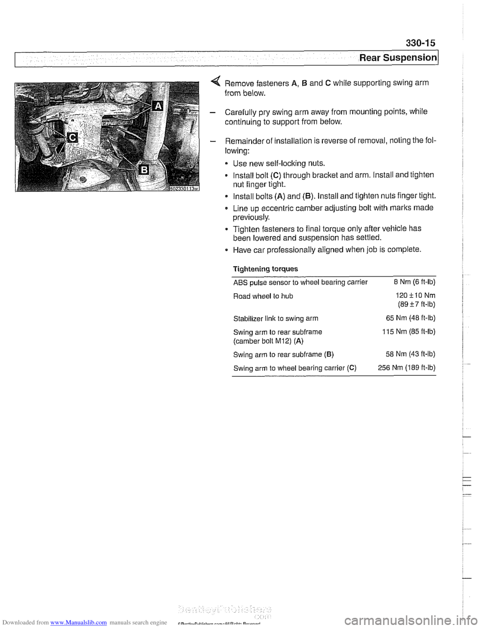
Remove fasteners A, B and C while supporting swing arm
from below.
Carefully pry swing arm away from mounting points, while
continuing to support from below.
Remainder of installation is reverse of removal, noting the fol-
lowing:
Use new self-locking nuts.
lnstall bolt
(C) through bracket and arm. Install and tighten
nut finger tight.
Install bolts
(A) and (6). Install and tighten nuts finger tight.
Line up eccentric camber adjusting bolt with marlts made
previously.
Tighten fasteners to final torque only after vehicle has
been lowered and suspension has settled.
Have car professionally aligned when job is complete.
Tightening torques
ABS pulse sensor to wheel bearing carrier 8 Nm (6 ft-lb)
Road wheel to hub
120+10 Nm
(89
i-7 ft-lb)
Stabilizer link to swing arm 65
Nm (48 ft-lb)
Swing arm to rear
subframe
(camber bolt M12) (A)
115 Nm (85 ft-lb)
Swing arm to rear
subframe (B) 58 Nm (43 ft-lb)
Swing arm
to wheel bearing carrier (C) 256 Nm (189 ft-lb)
Page 714 of 1002
Downloaded from www.Manualslib.com manuals search engine
--. -
Rear Suspension
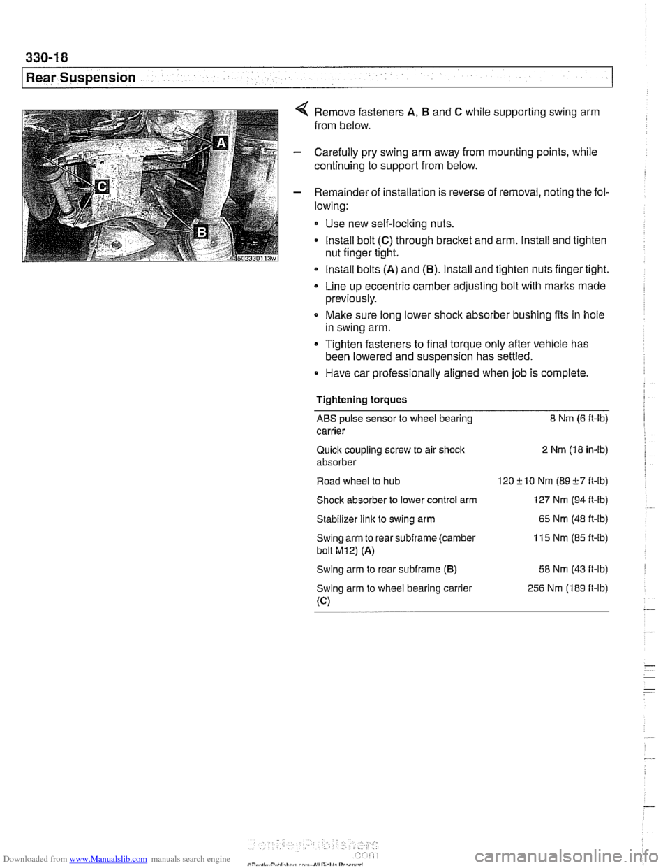
Remove fasteners A. B and C while supporting swing arm
from below.
Carefully pry swing arm away from mounting points, while
continuing to support from below.
Remainder of installation is reverse of removal, noting the fol-
lowing:
Use new self-locking nuts.
Install bolt
(C) through bracket and arm. Install and tighten
nut finger tight.
lnstall bolts (A) and
(6). Install and tighten nuts finger tight.
Line up eccentric camber adjusting bolt with rnarlts made
previously.
Make sure long lower shock absorber bushing fits in hole
in swing arm.
Tighten fasteners to final torque only afler vehicle has
been lowered and suspension has settled.
Have car professionally aligned when job is complete.
Tightening
torques
ABS pulse sensor to wheel bearing 8 Nm (6 It-lb)
carrier
Quiclc coupling screw to air shock 2 Nm (18 in-lb)
absorber
Road wheel to hub 120
210 Nm (89i-7 It-ib)
Shocic absorber
to lower control arm 127 Nm (94
ft-lb)
Stabilizer link to swing arm
65 Nm (48 ft-ib)
Swing arm to rear
subframe (camber 11 5 Nm (85 It-lb)
bolt M12) (A)
Swing arm to rear subframe (6) 58 Nm (43 It-lb)
Swing arm to wheel bearing carrier 256
Nm (189 It-lb)
(C)