turn BMW 540i 1999 E39 Workshop Manual
[x] Cancel search | Manufacturer: BMW, Model Year: 1999, Model line: 540i, Model: BMW 540i 1999 E39Pages: 1002
Page 419 of 1002
Downloaded from www.Manualslib.com manuals search engine
Fuel Injection
A faulty MAF sensor can produce the following problems:
Difficult to restart when engine is hot
Engine starts then stalls
* Engine starts and runs only with accelerator pedal de-
pressed
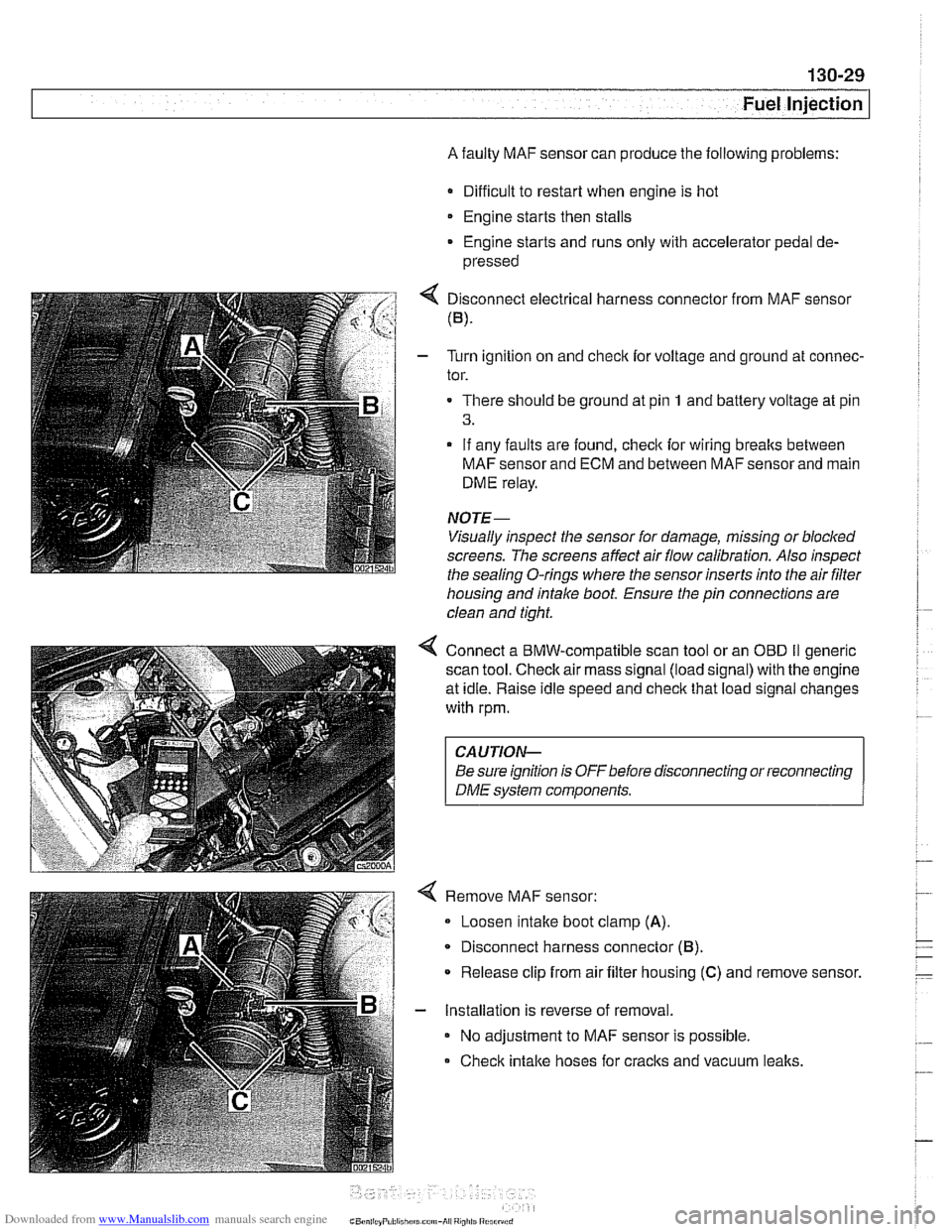
4 Disconnect electrical harness connector from MAF sensor
(B).
- Turn ignition on and checlc for voltage and ground at connec-
tor.
There should be ground at pin
1 and battery voltage at pin
3.
- If any faults are found, checlc for wiring breaks between
MAF sensor and ECM and between MAF sensor and main
DME relay.
NOTE-
Visually inspect the sensor for damage, missing or blocked
screens. The screens affect air flow calibration. Also inspect
the sealina
0-rinas where the sensor inserts into the air filter - - housing and intake boot. Ensure the pin connections are
clean and tight.
4 Connect a BMW-compatible scan tool or an OED II generic
scan tool.
Checlc air mass signal (load signal) with the engine
at idle. Raise idle speed and
checlc that load signal changes
with rpm.
CAUTION-
Be sure ignition is OFFbefore disconnecting or reconnecting
DME system components.
Remove MAF sensor:
Loosen intake boot clamp
(A).
Disconnect harness connector (6).
* Release clip from air filter housing (C) and remove sensor.
- Installation is reverse of removal.
No adjustment to MAF sensor is possible.
Check intake hoses for cracks and vacuum
lealts.
Page 422 of 1002
Downloaded from www.Manualslib.com manuals search engine
Fuel Injection
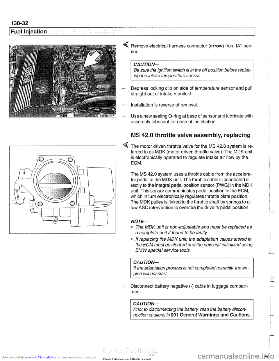
4 Remove electrical harness connector (arrow) from IAT sen-
sor.
CAUTION-
Be sure the ignition switch is in the off position before repiac-
ins the intake temperature sensor.
- Depress loclting clip on side of temperature sensor and pull
straight out of intake manifold.
- Installation is reverse of removal
- Use a new sealing O-ring at base of sensor and lubricate with
assembly lubricant for
ease of installation
MS 42.0 throttle valve assembly, replacing
< The motor driven throttle valve for the MS 42.0 system is re-
- ferred to as MDK (motor driven throttle valve). The MDK unit
is electronically operated to regulate intake air flow by the
ECM.
The
MS 42.0 system uses a throttle cable from the accelera-
tor pedal to the MDK unit. The throttle cable is connected di-
rectly to the integral pedal position sensor
(PWG) in the MDK
unit. This sensor communicates pedal position to the ECM,
which in turn electronically regulates throttle plate position.
The MDK pulley is linked to the throttle shaft by springs to al-
low ASC intervention to override the driver's pedal position.
NO TE -
The MDIC unit is non-adjustable and must be replaced as
a complete unit if found to be faulty.
if replacing the
MDK unit, the adaptation values stored in
the ECM must be clearedand the new unit initialized using
BMW special service tools.
CAUTION-
If the adaptation process is not completed correct& the en-
gine wiii
not start.
- Disconnect battery negative (-) cable in luggage compart-
ment.
CAUTION-
Prior to disconnecting the battern read the battely discon-
nection cautions in
001 General Warnings and Cautions.
Page 423 of 1002
Downloaded from www.Manualslib.com manuals search engine
Fuel lniection I
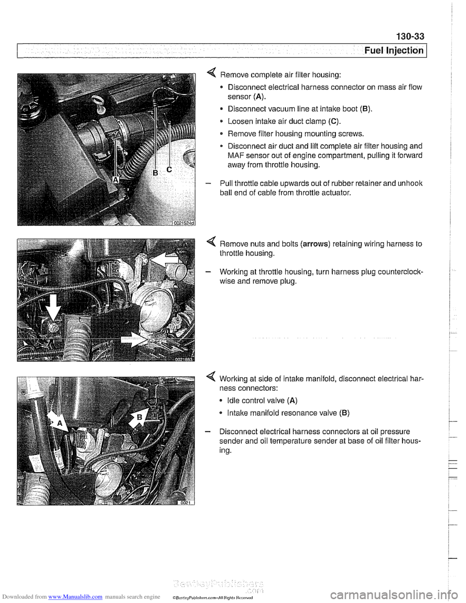
4 Remove complete air filter housing:
Disconnect electrical harness connector on mass air flow
sensor
(A).
Disconnect vacuum line at intake boot (B).
Loosen Intake air duct clamp (C).
Remove filter housing mounting screws
Disconnect air duct and
lift complete air filter housing and
MAF sensor out of engine compartment, pulling it forward
away from throttle housing.
- Pull throttle cable upwards out of rubber retainer and unhoolc
ball end of cable from throttle actuator.
4 Remove nuts and bolts (arrows) retaining wiring harness to
throttle housing.
- Working at throttle housing, turn harness plug counterclock-
wise and remove plug.
4 Working at side of intake manifold, disconnect electrical har-
ness connectors:
Idle control valve (A)
lntalce manifold resonance valve (B)
- Disconnect electrical harness connectors at oil pressure
sender and oil temperature sender at base of oil filter hous-
ing.
CO,l,> ti,, "F"bl,rl,irrm.,-AI ",",>ti
Page 424 of 1002
Downloaded from www.Manualslib.com manuals search engine
/Fuel Injection
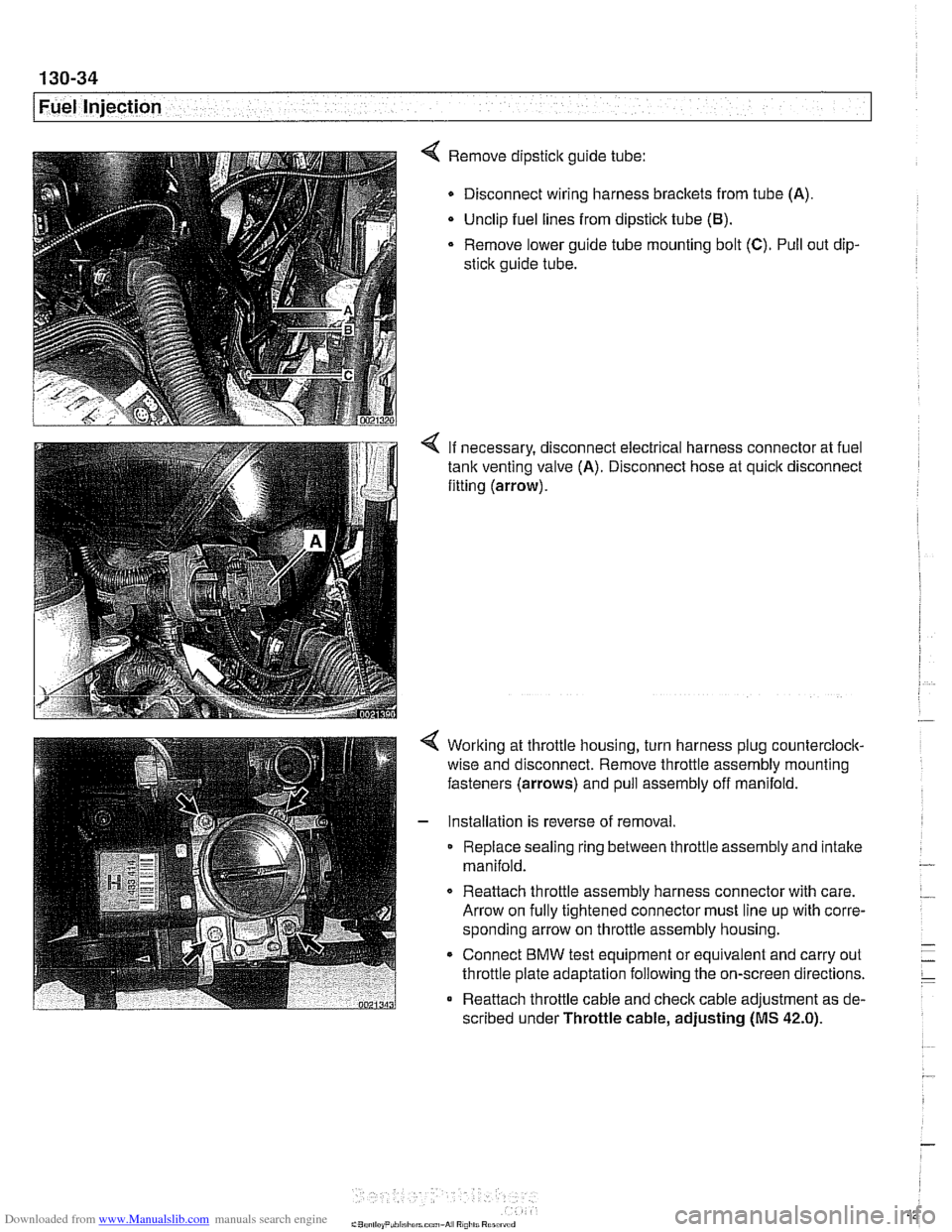
4 Remove dipstick guide tube:
Disconnect wiring harness brackets from tube (A).
Unclip fuel lines from dipstick tube
(El).
Remove lower guide tube mounting bolt (C). Pull out dip-
stick guide tube.
< If necessary, disconnect electrical harness connector at fuel
tank venting valve (A). Disconnect hose at quick disconnect
fitting (arrow).
Working at throttle housing, turn harness plug counterclock-
wise and disconnect. Remove throttle assembly mounting
fasteners (arrows) and pull assembly off manifold.
Installation is reverse of removal
Replace sealing ring between throttle assembly and intake
manifold.
0 Reattach throttle assembly harness connector with care.
Arrow on fully tightened connector must line up with corre-
sponding arrow on throttle assembly housing.
* Connect BMW test equipment or equivalent and carry out
throttle plate adaptation following the on-screen directions.
Reattach throttle cable and check cable adjustment as de-
scribed under Throttle cable, adjusting
(MS 42.0).
Page 426 of 1002
Downloaded from www.Manualslib.com manuals search engine
130-36
[~uel Injection
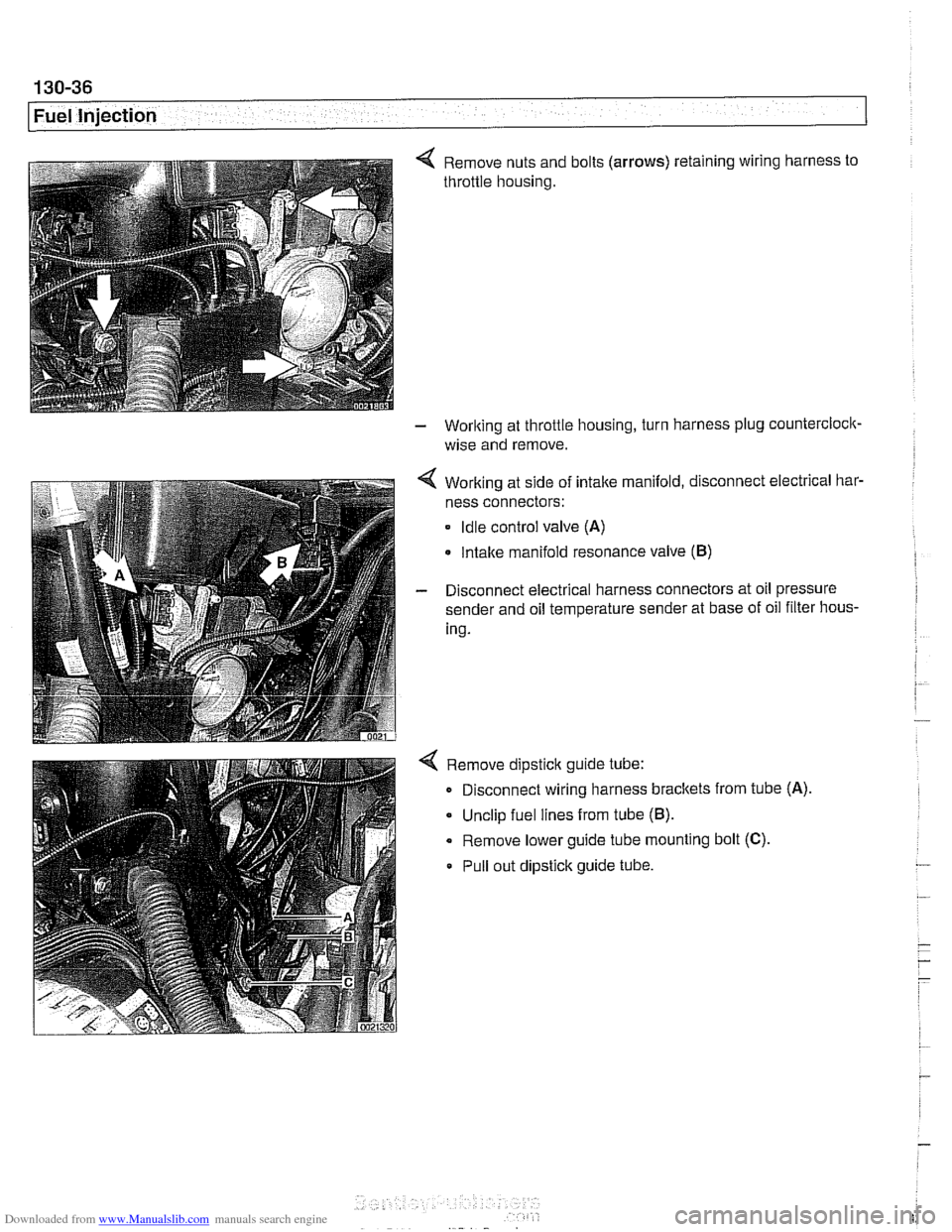
4 Remove nuts and bolts (arrows) retaining wiring harness to
throttle housing.
- Working at throttle housing, turn harness plug countercloclc
wise and remove.
4 Working at side of intake manifold, disconnect electrical bar-
ness connectors:
Idle control valve (A)
Intake manifold resonance valve (B)
- Disconnect electrical harness connectors at oil pressure
sender and oil temperature sender at base of oil filter hous-
ing.
4 Remove dipstick guide tube:
Disconnect wiring harness brackets from tube
(A)
Unclip fuel lines from tube (B).
Remove lower guide tube mounting bolt (C).
Pull out dipstick guide tube.
Page 427 of 1002
Downloaded from www.Manualslib.com manuals search engine
-.
Fuel Injection 1
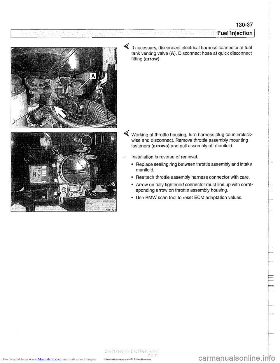
4 If necessary, disconnect electrical harness connector at fuel
tank venting valve (A). Disconnect hose at quick disconnect
fitting
(arrow).
< Worlting at throttle housing, turn harness plug counterclock-
wise and disconnect. Remove throttle assembly mounting
fasteners
(arrows) and pull assembly off manifold.
- Installation is reverse of removal.
0 Replace sealing ring between throttle assembly and intake
manifold.
Reattach throttle assembly harness connector with care.
0 Arrow on fully tightened connector must line up with corre-
sponding arrow on throttle assembly housing.
- Use BMW scan tool to reset ECM adaptation values.
Page 428 of 1002
Downloaded from www.Manualslib.com manuals search engine
130-38
Fuel Injection
Throttle cable, adjusting
(MS 42.0)
The throttle assembly on MS 42.0 cars uses a throttle cable.
The cable should be adjusted any time it is disconnected or
replaced. This procedure requires the factory scan tool or an
equivalent to read and adjust throttle angle. It is recommend-
ed the procedure be done by an authorized
BMW dealer ser-
vice department
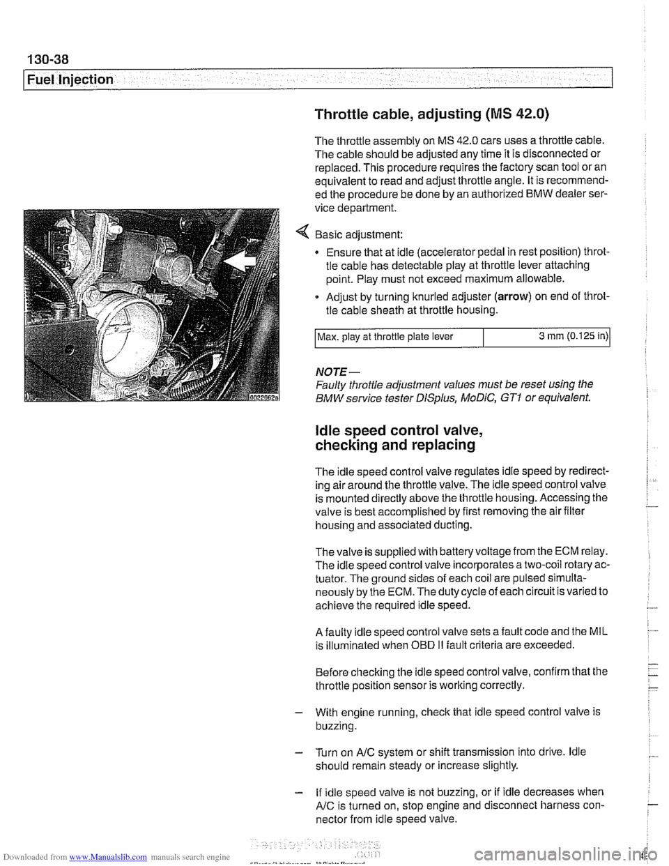
Basic adjustment:
Ensure that at idle (accelerator pedal in rest position) throt-
tle cable has detectable play at throttle lever attaching
point. Play must not exceed maximum allowable.
Adjust by turning knurled adjuster
(arrow) on end of throt-
tle cable sheath at throttle housing.
NOTE-
Faulty throttle adjustment values must be reset using the
BMW service tester
DISplus, MoDiC, GTI or equivalent.
Max.
play at throttle plate lever
ldle speed control valve,
checking and replacing
3 mm (0.125 in)
The Idle speed control valve regulates Idle speed by red~rect-
ing air around the throttle valve. The ldle speed control valve
is mounted
d~rectly above the throttle housing. Accessing the
valve is best accomplished by
flrst removing the air fllter
housing and associated ducting.
Thevalve is supplied with batteryvoltage from the ECM relay.
The idle speed control valve incorporates a two-coil rotary ac-
tuator. The ground sides of each coil are pulsed simulta-
neously by the ECM. The duty cycle of each circuit is varied to
achieve the required idle speed.
A faulty idle speed control valve sets a fault code and the MIL
is illuminated when
OED II fault criteria are exceeded.
Before checking the idle speed control valve, confirm that the
throttle position sensor is working correctly.
- With engine running, check that idle speed control valve is
buzzing.
- Turn on AIC system or shift transmission into drive. ldle
should remain steady or increase slightly.
- If idle speed valve is not buzzing, or if idle decreases when
AIC is turned on, stop engine and disconnect harness con-
nector from idle speed valve.
Page 431 of 1002
Downloaded from www.Manualslib.com manuals search engine
. -
Fuel Injection I
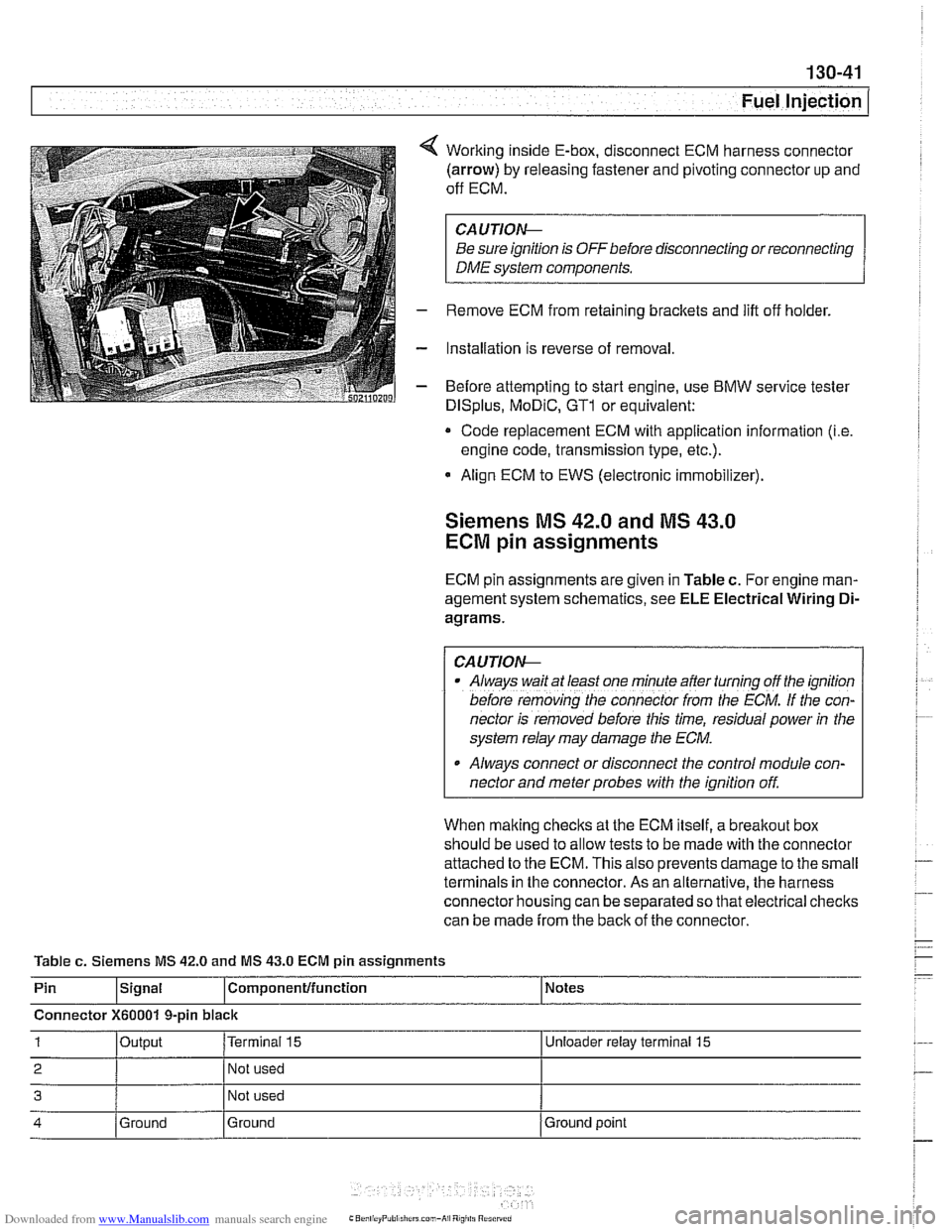
Working inside E-box, disconnect ECM harness connector
(arrow) by releasing fastener and pivoting connector up and
off ECM.
CA UTIOW
Be sure ignition is OFF before disconnecting or reconnecting
DME system components.
Remove ECM from retaining brackets and lift off holder.
Installation is reverse of removal
Before attempting to start engine, use
BMW service tester
DISplus, MoDiC, GTl or equivalent:
* Code replacement ECM with application information (i.e
engine code, transmission type, etc.).
Align ECM to EWS (electronic immobilizer).
Siemens MS 42.0 and MS 43.0
ECM pin assignments
ECM pin assignments are given in Table c. For engine man-
agement system schematics, see
ELE Electrical Wiring Di-
agrams.
/ CAUTIOW I
Al~ays wait at least one mfnule after turning off the ignition
before
remov;ng [he connecror irom rhe ECM. If the con-
nector is removed before this time, residual power
in the
system relay may damage the
ECM.
Always connect or disconnect the control module con-
nector and meter probes with the ignition off.
When making checks at the ECM itself, a
breakout box
should be used to allow tests to be made with the connector
attached to the ECM. This also prevents damage to the small
terminals in the connector. As an alternative, the harness
connector housing can be separated so that electrical checks
can be made from the back of the connector.
Table
c. Siemens MS 42.0 and MS 43.0 ECM pin assignments
Pin
lslgnal l~om~onentlfunction 1 Notes
Connector
X60001 9-pin black
1 loutput I~erminai 15 I Unloeder relay terminal 15
2 I 1 Not used I
3 Not used
4 Ground
Ground Ground
point
Page 440 of 1002

Downloaded from www.Manualslib.com manuals search engine
130-50
Fuel Injection
Bosch M5.2
ECM relay
1 HoL al ail iirnel XOL a1 ail limes
i--[-----i F109 (BOA) electronics I L.$.....: .I:
ECM relay . . . . . . . . . ,
8,s
:,
6 1 .. ... ~~.~~. . ...... .-, Engine control ii~~-~.~~..~ ........ ~~~~~~.~~~~:. module relay -;I
Of?
,c,;,,,
< With ignition off, remove ECM relay (arrow) in electronics
box (E-box) at right rear of engine compartment.
NOTE-
Relay locations can vary. Conh relay identification by
matcliing wiring colors and terminal numbers.
4 Check for voltage at terminal 6 of main relay socket (30-red
wire). On M5.2 cars also check for battery voltage at terminal
8.
. . . . . . . . . ,
If battery voltage is present, continue testing
.
If battery voltage is not present, check large red wire(s) in
relay socltet. See
ELE Electrical Wiring Diagrams.
%P,,tt
- Reinstall relay and turn ignition on. Gain access to underside
of relay socket and
checlc for ground at terminal 4 (85-brown
wire).
. . . . . . . . . . . . - - - - - - - - - . - - - . . l ,,-. ; Engine i f .: , ; Fuse carrier .,A . :engine /;is? /control L.!.!! .... 1.: ...... !.::..! I lij :module electronics If
ground is present, continue testing
If ground is not present, signal from ECM is missing. Checic
wire between ECM and relay.
4 With ignition on and relay installed, check for battery voltage
at terminal
2 (87-redlwhite wire). On M5.2.1 cars also checlc
for battery voltage at terminal 5.
If battery voltage is present, relay has energized and is
functioning correctly.
If battery voltage is not present and all earlier tests are OK,
relay is faulty and should be replaced.
Page 441 of 1002
Downloaded from www.Manualslib.com manuals search engine
130-51
Fuel Injection
Oxygen sensors, checking
The oxygen sensor provides an input voltage signal [0.2 vdc
(lean) to 0.8 vdc (rich)] to the
ECM based on the oxygen con-
tent in the exhaust gas. To generate voltage, the sensor tem-
perature must exceed 575"
F (300" C). Therefore the sensor
is electrically heated.
NO JE -
The test given below is not a conclusive test of oxygen sen-
sor efficiency and does not test how the oxygen sensor re-
acts to changing conditions. Pin numbers and wire colors
can vary Always check the wiring diagrams to confirm wire
color and pin assignment.
0 The oxygen sensorconnectorplugs are locatednext to the
catalytic converters.
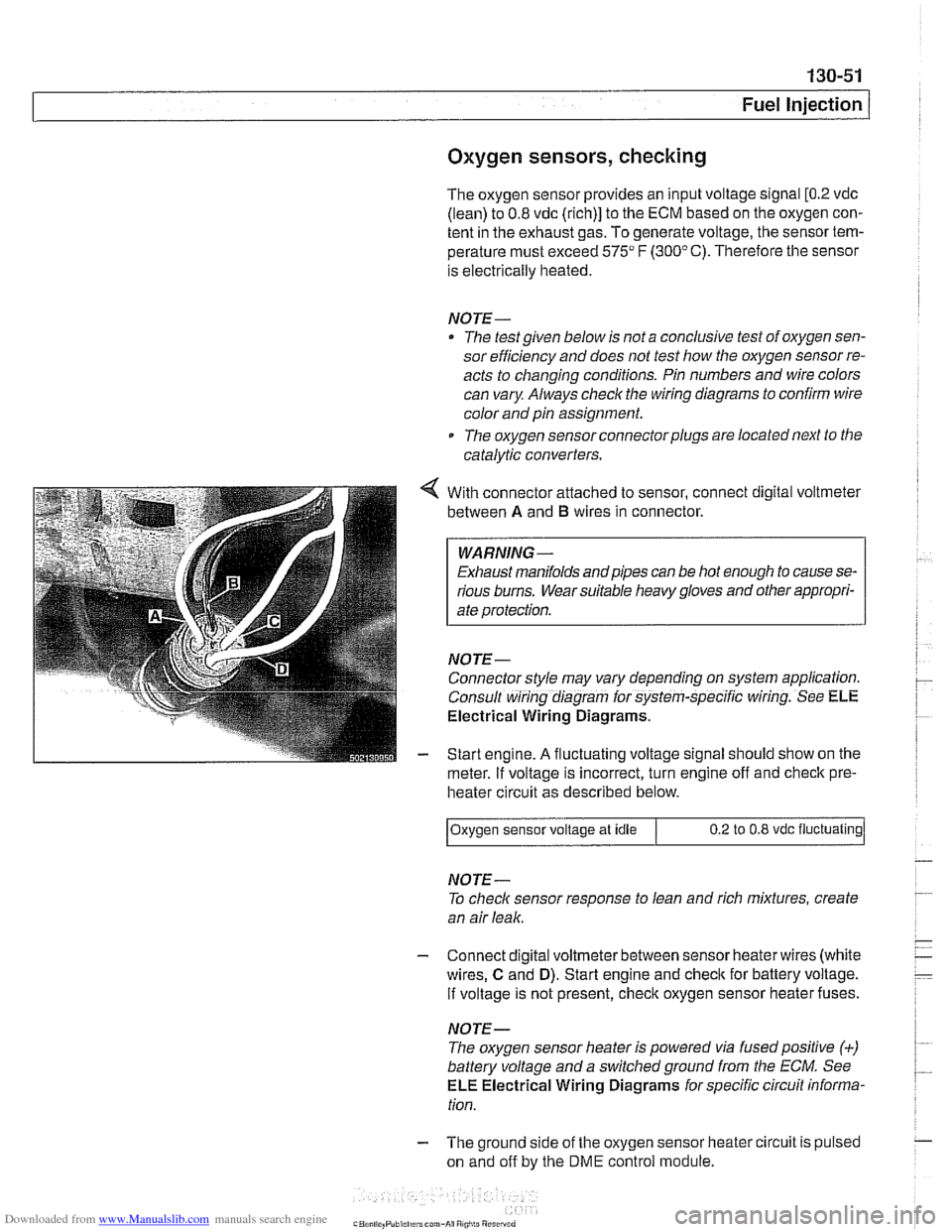
With connector attached to sensor, connect digital voltmeter
between
A and B wires in connector.
WARNING -
Exhaust manifolds andpipes can be hot enough to cause se-
rious burns. Wear suitable heavy gloves and other appropri-
ate protection.
NOJE-
Connector style may vary depending on system application.
Consult wiring diagram for system-specific wiring. See
ELE
Electrical Wiring Diagrams.
Start engine.
A fluctuating voltage signal should show on the
meter.
If voltage is incorrect, turn engine off and check pre-
heater circuit as described below.
NOJE-
To check sensor response to lean and rich mixtures, create
an air leak.
Oxygen sensor
voltage at idle
- Connect digital voltmeterbetween sensor heaterwires (white
wires,
C and D). Start engine and check for battery voltage.
If voltage is not present, check oxygen sensor heater fuses.
0.2 to 0.8 vdc fluctuating
NOJE-
The oxygen sensor heater is powered via fusedpositive (+)
battery voltage and a switchedground from the ECM. See
ELE Electrical Wiring Diagrams for specific circuit informa-
tion.
- The ground side of the oxygen sensor heater circuit is pulsed
on and off by the
DME control module.