turn BMW 540i 1999 E39 Workshop Manual
[x] Cancel search | Manufacturer: BMW, Model Year: 1999, Model line: 540i, Model: BMW 540i 1999 E39Pages: 1002
Page 444 of 1002
Downloaded from www.Manualslib.com manuals search engine
130-54
I Fuel Injection ldle speed control valve,
testing and replacing
ldle speed is maintained by the ECM through the idle speed
control valve. The idle control function compensates for en-
gine load and engine operating conditions. ldle speed is
adaptive through the ECM and no adjustments can be made.
Before checking valve, confirm that throttle position sensor is
working correctly.
NOTE-
The test given below is an electrical check only. It does not
check the mechanical operation of the valve. If the valve is
sticking, hanging up or is sluggish in operation, substituting a
Inown good valve is the best way to check it.
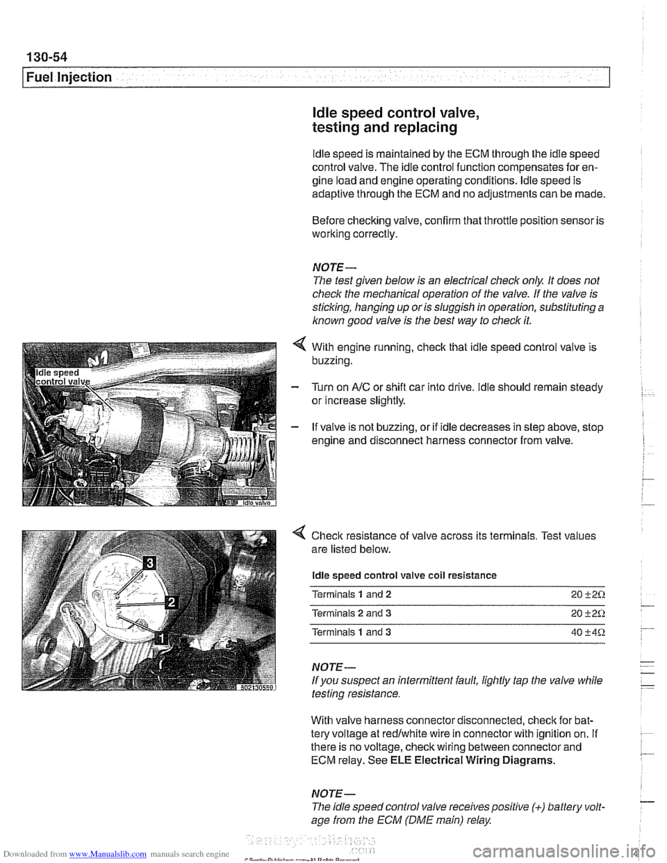
With engine running, check that idle speed control valve is
buzzing.
Turn on
AIC or shift car into drive. ldle should remain steady
or increase slightly.
If valve is not buzzing, or if idle decreases in step above, stop
engine and disconnect harness connector from valve.
4 Check resistance of valve across its terminals. Test values
are listed below.
ldle speed control valve coil resistance
Terminals
1 and 2 20 +2%
Terminals 2 and 3 20 +2Q
Terminals 1 and 3 40 +4%
NOTE-
If you suspect an intermittent fault, lightly tap the valve while
testing resistance.
With valve harness connector disconnected, check for bat-
tery voltage at redlwhite wire in connector with ignition on.
If . ~~ ~~
there is no voltage, check wiring between connector and 7 ECM relay. See ELE Electrical Wiring Diagrams.
NOTE- - The idle speed control valve receivespositive (+) battery volt-
age from the ECM (DME main) relay
Page 447 of 1002
Downloaded from www.Manualslib.com manuals search engine
Fuel Injection
Intake air temperature
([AT) sensor,
testing and replacing
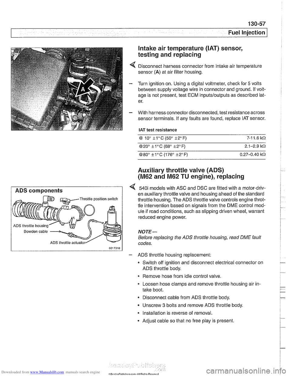
Disconnect harness connector from intake air temperature
sensor
(A) at air filter housing.
Turn ignition on. Using a digital voltmeter, check for
5 volts
between supply voltage wire in connector and ground.
If volt-
age is not present, test ECM
inputs/outputs as described lat-
er.
With harness connector disconnected, test resistance across
sensor terminals. If any faults are found, replace IAT sensor.
IAT test resistance
0 lV *lac (50" i-2°F) 7-1 1.6 k.0.
020' kl°C (68' 322°F) 2.1-2.9 it.0.
080" ?lac (176" i-2°F) 0.27-0.40 itn
Auxiliary throttle valve (ADS)
(M62 and M62 TU engine), replacing
ADS components 540i models with ASC and DSC are fitted with a motor-driv-
en auxiliary throttle valve and housing ahead of the standard Throttle position switch throttle housing. The ADS throttle valve controls engine throt-
tle intervention based on signals from the DME control mod-
ule if road conditions, such as slipping driven wheel, warrant
reduced engine power.
ADS throttle housing
Bowden cable NOTE-
Before replacing the ADS throttle housing, read DME fault
ADS lhroltle actualor codes.
- ADS throttle housing replacement:
Switch off ignition and disconnect electrical connector on
ADS throttle body.
Remove hose from idle control valve.
Loosen hose clamps and remove throttle housing air in-
take boot.
Disconnect cable from ADS throttle body.
- Unscrew 3 bolts and remove ADS throttle body.
Installation is reverse of removal.
- Adjust cable so that no free play is present.
Page 458 of 1002
Downloaded from www.Manualslib.com manuals search engine
130-68
Fuel Injection
0
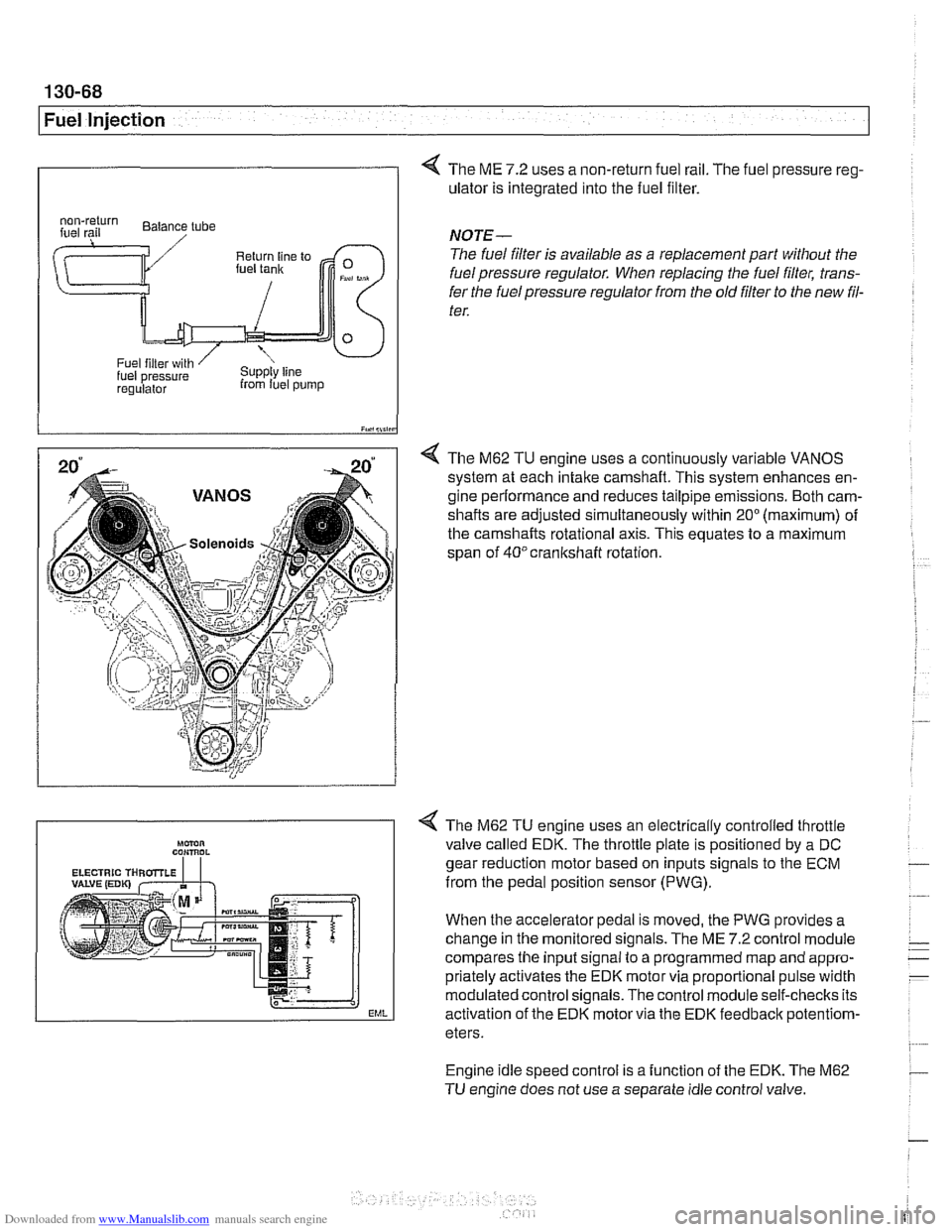
4 The ME 7.2 uses a non-return fuel rail. The fuel pressure reg-
ulator is integrated into the fuel filter.
I iY.,lii,in
4 The M62 TU engine uses a continuously variable VANOS
system at each intake camshaft. This system enhances en-
gine performance and reduces tailpipe emissions. Both cam-
shafts are adjusted simultaneously within
20" (maximum) of
the camshafts rotational axis. This equates to a maximum
span of
40°crankshaft rotation.
regulalor from luel pump
NOTE-
The fuel filter is available as a replacement part without the
fuel pressure regulator. When replacing the fuel filter, trans-
fer the fuel pressure regulator from the old
filter to the new fil-
ter.
Engine idle speed control is a function of the EDK. The M62
TU engine does not use a separate idle control valve.
Mmn CON,ROL
EML
< The M62 TU engine uses an electrically controlled throttle
valve called EDK. The throttle plate is positioned by a DC
gear reduction motor based on inputs signals to the ECM
from the pedal position sensor (PWG).
When the accelerator pedal is moved, the PWG provides a
change in the monitored signals. The ME
7.2 control module
compares the input signal to a programmed map and appro-
priately activates the EDK motor via proportional pulse width
modulated control signals. The control module self-checks its
activation of the EDK motor via the EDK feedbaclc
potentiom-
eters.
Page 460 of 1002
Downloaded from www.Manualslib.com manuals search engine
130-70
Fuel Injection
ECM relay
--
CAUTION-
Relay positions can vary Be sure to confirm relay position by
identifying the wiring in the
socl(et using the wiring diagrams
in ELE Electrical Wiring Diagrams.
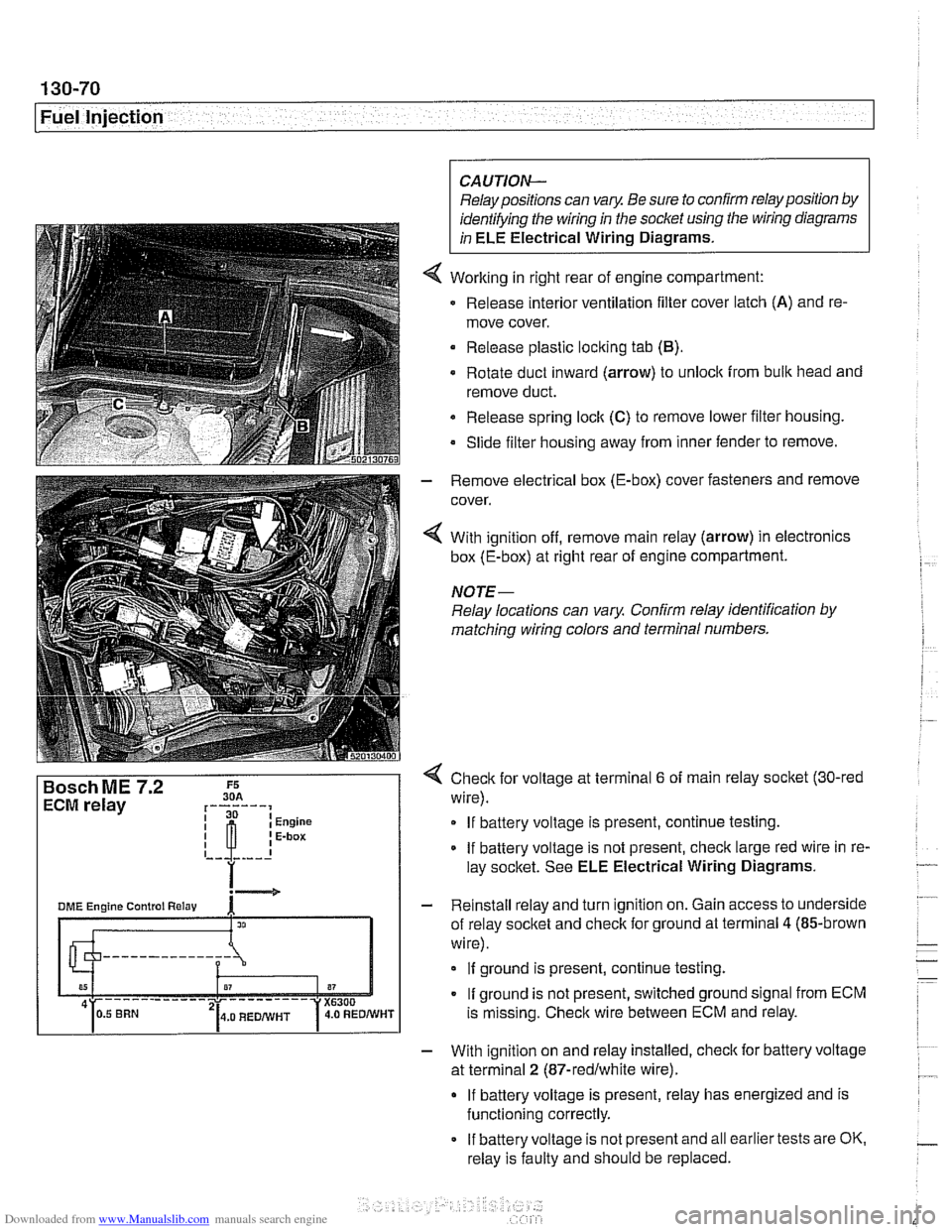
Working in right rear of engine compartment:
Release interior ventilation filter cover latch
(A) and re-
move cover.
Release plastic locking tab
(B).
Rotate duct inward (arrow) to unlock from bulk head and
remove duct.
Release spring
loclt (C) to remove lower filter housing.
Slide filter housing away from inner fender to remove.
- Remove electrical box (E-box) cover fasteners and remove
cover.
4 With ignition off, remove main relay (arrow) in electronics
box (E-box) at right rear of engine compartment.
NOTE-
Relay locations can vary Confirm relay identification by
matching wiring colors and terminal numbers.
4 Check for voltage at terminal 6 of main relay socket (30-red
wire).
If battery voltage is present, continue testing.
If battery voltage is not present, check large red wire in re-
lay socltet. See ELE Electrical Wiring Diagrams.
- Reinstall relay and turn ignition on. Gain access to underside
of relay socket and check for ground at terminal
4 (85-brown
wire).
If ground is present, continue testing.
If ground is not present, switched ground signal from ECM
is missing. Check wire between ECM and relay.
- With ignition on and relay installed, check for battery voltage
at terminal
2 (87-redlwhite wire).
If battery voltage is present, relay has energized and is
functioning correctly.
If battery voltage is not present and all earlier tests are OK.
relay is faulty and should be replaced.
Page 465 of 1002
Downloaded from www.Manualslib.com manuals search engine
130-75
Fuel Injection
Secondary air injection, overview
The secondary air system pumps ambient air into the exhaust
stream afteracoid engine start to reduce the warm-up time of
the catalytic converters and to reduces HC and CO emis-
sions. The ME
7.2 ECM controls and monitors the secondary
air injection system. The secondary air pump operates at a
starttemperature of between 10°C
(50°F) and 40°C (104°F).
and continues to operate for a maximum of
2 minutes at idle
speed.
The electric air pump draws in ambient air and supplies it to
the
checlc valve. The vacuum vent valve (solenoid) switches
vacuum to open the
checlc valve when activated by the ECM.
Once opened, the checlc
valve allows air to be pumped into
the exhaust stream.
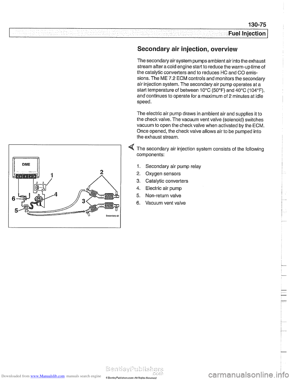
4 The secondary air injection system consists of the following
components:
1. Secondary air pump relay
2. Oxygen sensors
3. Catalytic converters
4. Electric air pump
5. Non-return valve
6. Vacuum vent valve
Page 473 of 1002
Downloaded from www.Manualslib.com manuals search engine
Fuel Tank and Fuel Pump
Fuel pump
The electric fuel pump is mounted in the fuel tank in tandem
with the right side fuel level sender. The fuel pump delivers
pressurized fuel to the fuel injection system.
A pressure regu-
lator maintains system pressure. The quantity of fuel supplied
exceeds demand, so excess fuel returns to the fuel tank via a
return line. See
130 Fuel Injection for more information.
NOTE-
Fuel pump removal procedures are given under Fuel level
sender (right side) and fuel pump, removing and install-
ing.
Fuel tank evaporative control system
Evaporative control, also referred to as running losses con-
trol, is designed to prevent fuel system evaporative losses
from venting into the atmosphere.
The components of this system allow control and monitoring
of evaporative losses by the on-board diagnostic
(OED II)
software incorporated into the engine control module (ECM).
NOTE-
1997 V-8 models (540i) with Bosch DME M5.2 are not
equipped with an
OBD I1 running losses monitoring system.
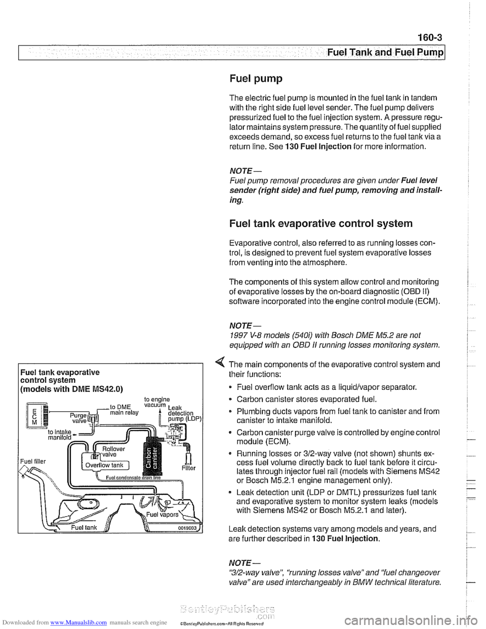
Fuel tank evaporative
control system
(models with
DME MS42.0)
4 The main components of the evaporative control system and
their functions:
Fuel overflow
tank acts as a liquidlvapor separator
Carbon canister stores evaporated fuel.
Plumbing ducts vapors from fuel tank to canister and from
canister to intake
manifold.
- Carbon canister purge valve is controlled by enginecontrol
module (ECM).
Running losses or 312-way valve (not shown) shunts ex-
cess fuel volume directly
back to fuel tank before it circu-
lates through injector fuel rail (models with Siemens MS42
or Bosch M5.2.1 engine management only).
Leak detection unit (LDP or DMTL) pressurizes fuel
tank
and evaporative system to monitor system leaks (models
with Siemens MS42 or Bosch M5.2.1 and later).
Leak detection systems vary among models and years, and
are further described in
130 Fuel Injection.
NOTE -
"3/2-way valve", 'tunning losses valve" and "fuel changeover
valve" are used interchangeably
in BMW technical literature.
Page 475 of 1002
Downloaded from www.Manualslib.com manuals search engine
Fuel Tank and Fuel Pump
Warnings and cautions
Observe the following warnings and cautions when servicing
the fuel system.
WARNING-
* The fuel system is designed to retain pressure even when
the ignition is off. When working with the fuelsystem, loos-
en the fuel lines slowly to allow residual
fuel pressure to
dissipate. Avoid spraying fuel. Use shop rags to capture
leaking fuel.
Before beginning any work on the fuel system, place a
fire extinguisher in the vicinity of the work area.
Fuel is highly flammable. When working around fuel, do
not disconnect any wires that could cause electrical
sparks. Do not smoke or worknearheaters or other fire
hazards.
* Always unscrew the fuel tank cap to release pressure
in the
tanlc before working on the tank or lines.
When disconnecting a fuel hose, wrap shop rag around
end of hose to prevent spray of fuel under pressure.
Do not use a work light with an incandescent bulb near
any fuel. Fuel may spray on the hot bulb causing a fire.
0 Make sure the worlc area is properly ventilated.
CAUTION-
- Prior to disconnecting the battery, read the battery discon-
nection cautions given in
001 General Cautions an4
Warnings.
Before
making any electrical tests with the ignition
turned on, disable the ignition system as described in
120 Ignition System. Be sure the battery is discon-
nected when replacing components.
To prevent damage to the ignition system or other DME
components, including the engine control module
(ECM), always connect and disconnect wires and test
equipment with the ignition off.
Cleanliness is essential when
worl~ing with the fuel sys-
tem. Thoroughly clean the fuel line unions before dis-
connecting any of the lines.
Use only clean tools. Keep removed parts clean and
sealed or covered with a clean, lint-free cloth, especial-
ly if completion of the repair is delayed.
Do not move the car while the fuel system is open.
Avoid using high pressure compressed air to blow out
lines and components. High pressure can rupture inter-
nal seals and gaskets.
Always replace seals, O-rings and hose clamps.
Page 479 of 1002
Downloaded from www.Manualslib.com manuals search engine
.- -
Fuel Tank and Fuel purnpl
Fuel pump power consumption, testing
To achieve accurate test results, the battery voltage at the
fuel pump connector should be
12.6 volts. Charge the battery
as necessary.
A higher than normal power consumption may indicate a
worn fuel pump, which may cause intermittent fuel starvation
due to pump overheating and seizure. The only remedy is
pump replacement.
A lower than normal power consumption
may indicate a blockage. Be sure to check that the return line
and the pump pickup are not obstructed before replacing the
pump.
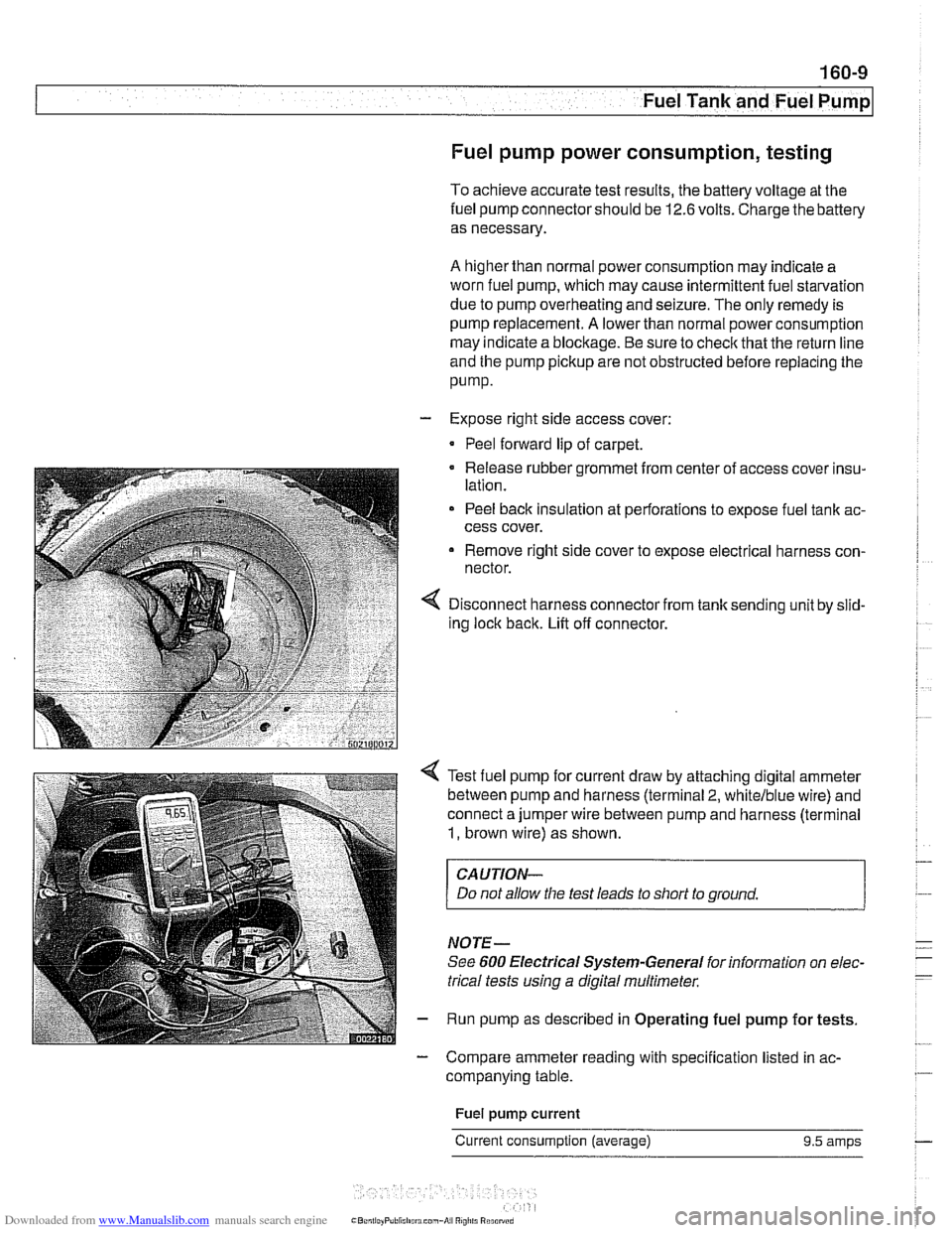
- Expose right side access cover:
Peel forward lip of carpet.
Release rubber grommet from center of access cover insu-
lation.
Peel back insulation at perforations to expose fuel tank ac-
cess cover.
Remove right side cover to expose electrical harness con-
nector.
Disconnect harness connector from tank sending unit by slid-
ing lock back. Lift off connector.
Test fuel pump for current draw by attaching digital ammeter
between pump and harness (terminal
2, whitelblue wire) and
connect a jumper wire between pump and harness (terminal
1, brown wire) as shown.
CAUTION-
Do not allow the test leads to short to ground.
NOTE-
See 600 Electrical Systern-General for information on elec-
trical tests
using a digital multirneter.
Run pump as described in Operating fuel pump for tests.
- Compare ammeter reading with specification listed in ac-
companying table.
Fuel
pump current
Current consumption (average) 9.5 amps
Page 480 of 1002
Downloaded from www.Manualslib.com manuals search engine
I Fuel Tank and Fuel Pump --
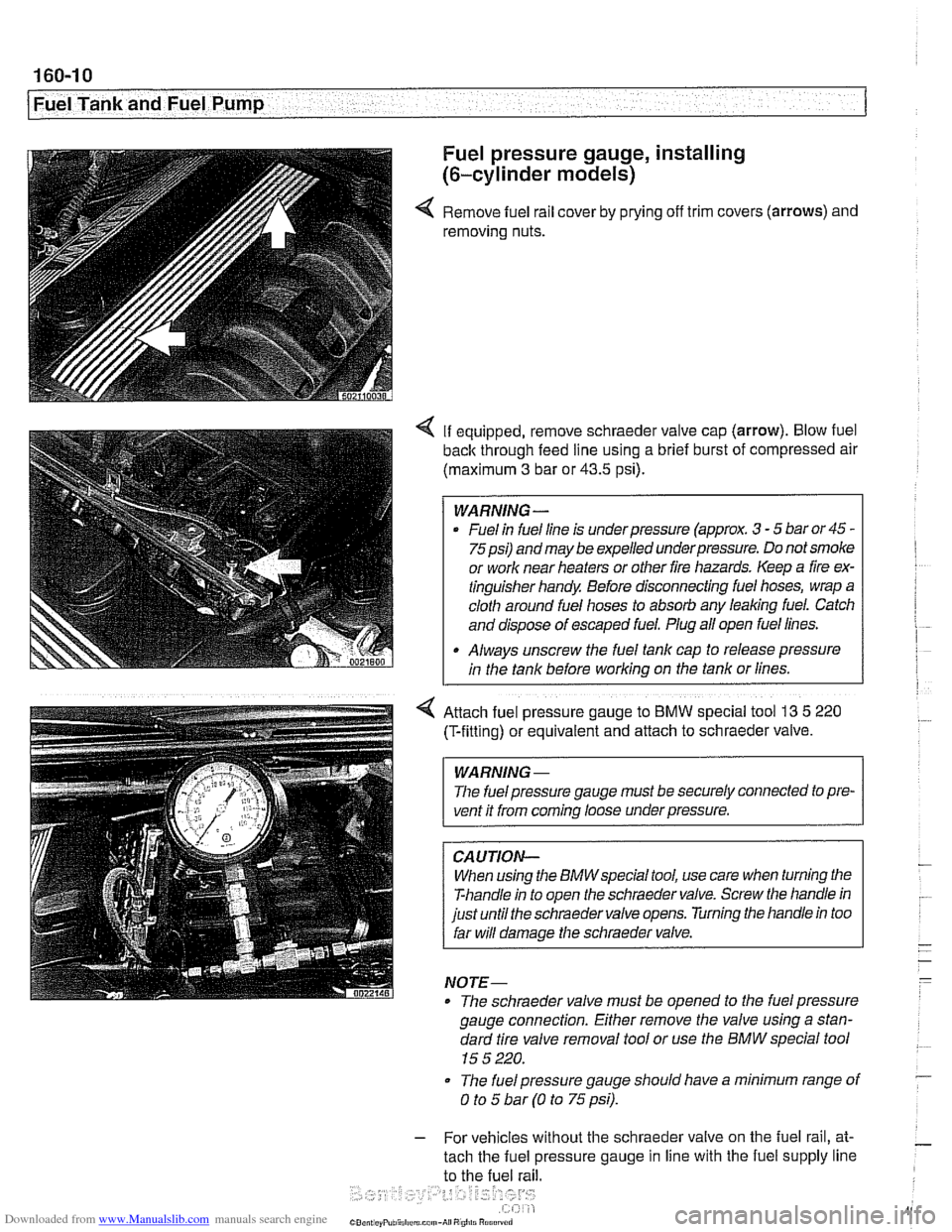
Fuel pressure gauge, installing
(6-cylinder models)
4 Remove fuel rail cover by prying off trim covers (arrows) and
removing nuts.
4 If equipped, remove schraeder valve cap (arrow). Blow fuel
back through feed line using a brief burst of compressed air
(maximum
3 bar or 43.5 psi).
WARNING -
Fuel in fuel line is underpressure (approx. 3 - 5 bar or 45 -
75psi) andmay be expelled underpressure. Do not smoke
or work near heaters or other fire hazards. Keep a fire ex-
tinguisher handy Before disconnecting fuel hoses, wrap a
cloth around fuel hoses to absorb any leaking fuel. Catch
and dispose of escaped fuel. Plug all open fuel lines.
Always unscrew the fuel tank cap to release pressure
in the tank before working on the tank or lines.
4 Attach fuel pressure gauge to BMW special tool 13 5 220
(T-fittlng) or equivalent and attach to schraeder valve.
WARNING -
The fuel pressure gauge must be securely connected to pre-
vent it from
coming loose underpressure.
CAUTION-
When using the BMWspecial tool, use care when turning the
T-handle in to open the schraeder valve. Screw the handle in
just until the schraeder valve opens. Turning the handle in too
far will damage the schraeder valve.
NOTE-
* The schraeder valve must be opened to the fuel pressure
gauge connection. Either remove the valve using a stan-
dard tire valve removal tool or use the BMW special tool
15 5 220.
* The fuel pressure gauge should have a minimum range of
0 to 5 bar (0 to 75 psi).
- For vehicles without the schraeder valve on the fuel rail, at-
tach the fuel pressure gauge in line with the fuel supply line
to the fuel rail.
Page 481 of 1002
Downloaded from www.Manualslib.com manuals search engine
Fuel Tank and Fuel Pump
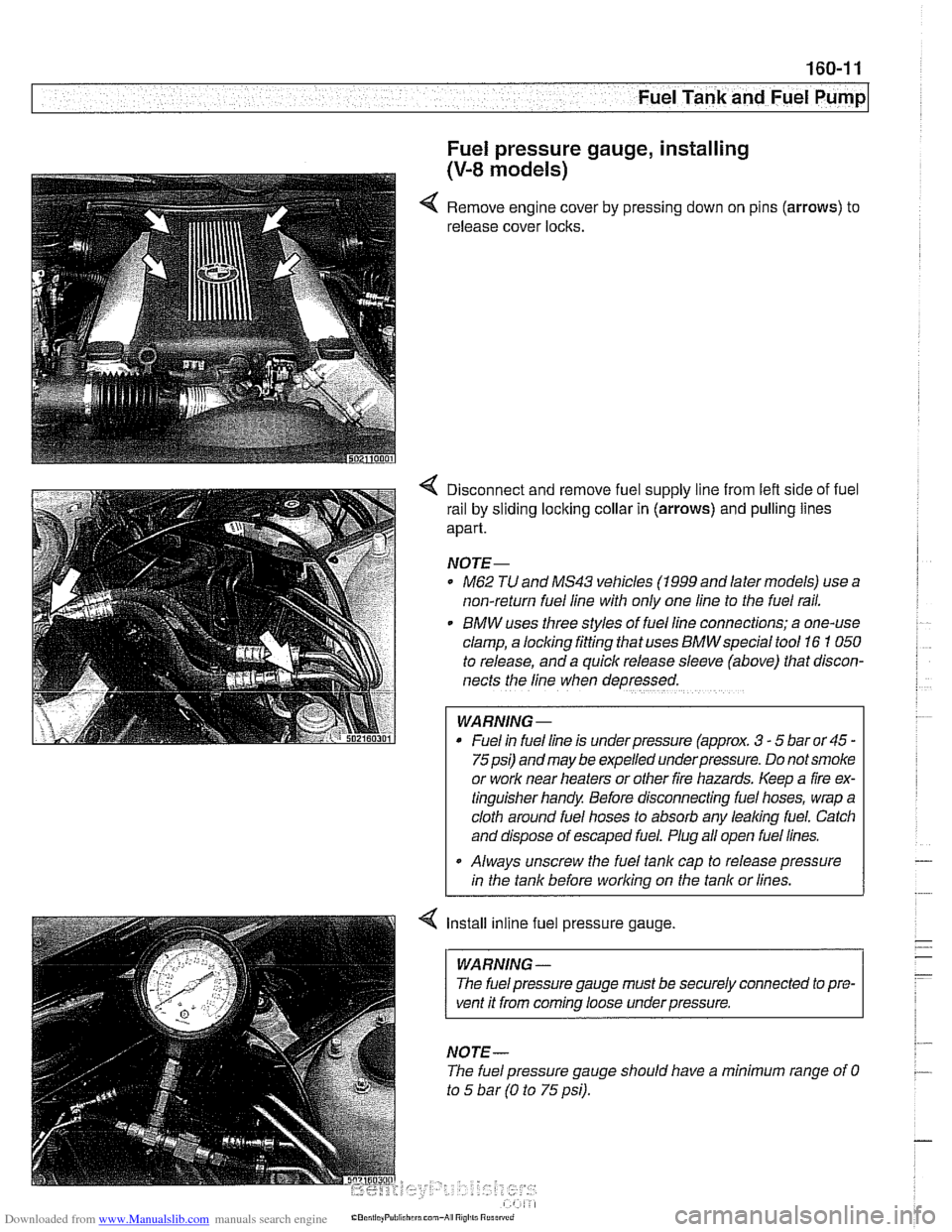
Fuel pressure gauge, installing
(V-8 models)
Remove engine cover by pressing down on pins (arrows) to
release cover locks.
4 Disconnect and remove fuel supply line from lefl side of fuel
rail by sliding
loclting collar in (arrows) and pulling lines
apart.
NOTE-
* ME2 TU and MS43 vehicles (1999 and later models) use a
non-return fuel line with only one line to the fuel
rafl.
BMW uses three styles of fuellfne connections; a one-use
clamp, a locking fitting that uses
BMWspeclal tool 16 1 050
to release, and a quick release sleeve (above) that discon-
nects the line when depressed.
WARNING -
* Fuel In fuel line is under pressure (approx. 3 - 5 bar or 45 -
75psi) and may be expelled underpressure. Do not smoke
or work near heaters or other fire hazards. Keep a fire ex-
tinguisher handy. Before disconnecting fuel hoses, wrap a
cloth around fuel hoses to absorb any
lealiing fuel. Catch
and dispose of escaped fuel. Plug all open fuel lines.
Always unscrew the fuel tank cap to release pressure
in the tank before workina on the tank or lines.
< Install inline fuel pressure gauge.
WARNING -
The fuel pressure gauge must be securely connected to pre-
vent it from coming loose underpressure.
NOTE-
The fuel pressure gauge should have a minimum range of 0
to 5 bar (0 to 75 psi).