turn BMW 540i 1999 E39 Owners Manual
[x] Cancel search | Manufacturer: BMW, Model Year: 1999, Model line: 540i, Model: BMW 540i 1999 E39Pages: 1002
Page 393 of 1002
Downloaded from www.Manualslib.com manuals search engine
-
Fuel Injection
of diagnostic time and to help avoid incorrect component re-
placement and possible damage to system components.
NOTE-
* Professional diagnostic scan tools available at the time of
this printing include the BMW factory tools and a small
number of aftermarket BMW-specific tools. The
CS2000
from Baum Tools Unlimited, the Retriever from Assenma-
chef Specialty Tools, and the MT2500 from Snap-on are
three examples.
In addition to the BMW-specific professional line of scan
tools, there are inexpensive generic OBD
I1 scan tool soft-
ware programs and
handheld units available. Although
these tools have limited capabilities as compared to the
dedicated tools, they are powerful diagnostic tools.
For the
DIY owner, simple aftermarltet DTC readeris avail-
able through
http://www.pealteresearch.com. This tool is
capable of checlting for
DTCs as well as turning off the il-
luminated
MIL and resetting the service indicator lights.
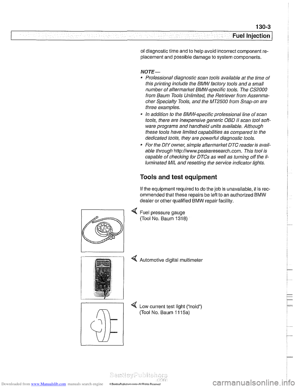
Tools and test equipment
If the equipment required to do the job is unavailable, it is rec-
ommended that these repairs be left to an authorized
BMW
dealer or other qualified BMW repair facility.
4 Low current test light ("noid")
(Tool No. Baum 11 15a)
Page 395 of 1002
Downloaded from www.Manualslib.com manuals search engine
Fuel Injection
Warnings and cautions
For personal safety, as well as the protection of sensitive
electronic components, adhere to the warnings and cautions
on the following pages.
WARNING-
Gasoline is highly flammable and its vapors are explosive.
Do not smoke or work on a car near heaters or other fire
hazards when diagnosing and repairing fuel system prob-
lems. Have a fire extinguisher available in case of an emer-
gency
Renew fuel system hoses, clamps and O-rings any
time they are removed.
When working on an open fuel system, wear suitable
hand protection, as prolonged contact
with fuel can
cause illnesses and skin disorders.
* The ignition system produces high voltages that can be
fatal. Avoid contact with exposed terminals. Use ex-
treme caution when
working on a car with the ignition
switched on or the engine running.
CAUTION-
- Disconnecting the battery may erase fault code($ storedin
memory Check for fault codes prior to disconnecting the
battery cables. Read the battery disconnection cautions in
001 General Warnings and Cautions.
a Connect and disconnect the DME system wiring and
1 test equipment leads only when the ignition is switched
off.
Wait at least 1 minute after turning off the ignition be-
fore removing the engine control module (ECM) con-
nector. If the connector is removed before this time,
residualpower in the system relay may damage the
control module.
Fuel system cleaners and other chemical additives oth-
er than those specifically recommended by BMW may
damage the catalytic converter, the oxygen sensor or
other fuel supply components.
* Do not connect any test equipment that delivers a 12-
volt power supply to terminal 15 (+) of the ignition coil.
The current flow may damage the ECM. In general,
connect test equipment only as specified by BMW or
the equipment maker.
Only use a digital
multirneter for electrical tests. Only
use an LED test light for
quiclc tests.
Page 398 of 1002
Downloaded from www.Manualslib.com manuals search engine
130-8
Fuel Injection
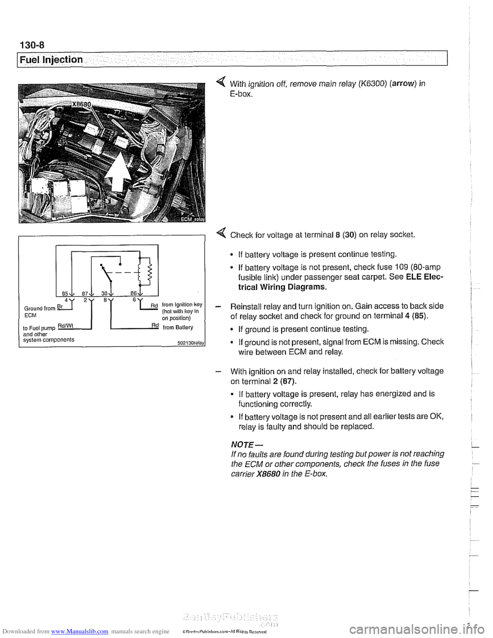
With ignition off, remove main relay (K6300) (arrow) in
E-box.
- With ignition on and relay installed, check for battery voltage
on terminal
2 (87).
4 Check for voltage at terminal 8 (30) on relay socket.
If battery voltage is present, relay has energized and is
functioning correctly.
Gmund from 6L (hot ~4th k~y key in Ern
2I '1
on position)
to
Fuel pump RdiWt Rd from Battery and other system components SOZI~O~~I~Y
If battery voltage is not present and all earlier tests are OK,
relay is faulty and should be replaced.
If
battery voltage is present continue testing.
If battery voltage is not present, check fuse 109 (80-amp
fusible link) under passenger seat carpet. See ELE Elec-
trical Wiring Diagrams.
- Reinstall relay and turn ignition on. Gain access to back side
of relay socket and check for ground on terminal
4 (85).
If ground is present continue testing.
If ground is not present, signal from ECM is missing. Check
NOTE-
If no faults are found during testing but power is not reaching
the
ECM or other components, check the fuses in the fuse
carrier
X8680 in the E-box.
wire
between ECM and relay.
Page 399 of 1002
Downloaded from www.Manualslib.com manuals search engine
Fuel Injection I
Mass air flow (MAF) sensor,
checking and replacing
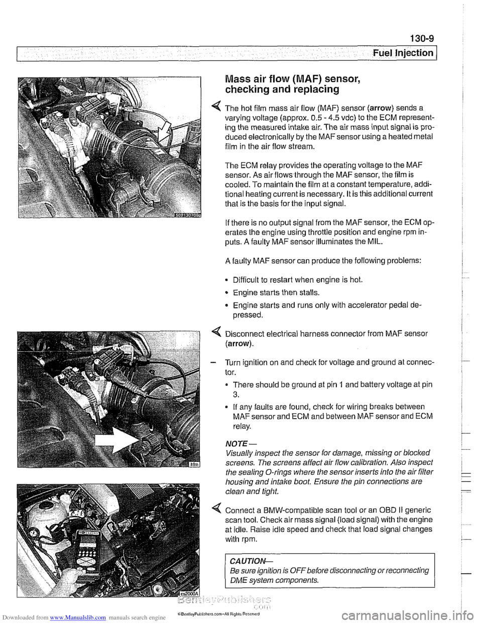
4 The hot film mass air flow (MAF) sensor (arrow) sends a
varying voltage (approx.
0.5 - 4.5 vdc) to the ECM represent-
ing the measured intake air. The air mass input signal is pro-
duced electronically by the
MAFsensorusing a heated metal
film in the air flow stream.
The ECM relay provides the operating voltage to the MAF
sensor. As air flows through the MAF sensor, the film is
-
cooled. To maintain the film at a constant temperature, addi-
tional heating current is necessary. It is this additional current
that is the basis for the input signal.
If there is no output signal from the MAF sensor, the ECM op-
erates the engine using throttle position and engine rpm in-
puts. A faulty MAF sensor illuminates the MIL.
A faulty MAF sensor can produce the following problems:
Difficult to restart when engine is hot.
Engine starts then stalls.
Engine starts and runs only with accelerator pedal de-
pressed.
Disconnect electrical harness connector from MAF sensor
(arrow).
- Turn ignition on and check for voltage and ground at connec-
tor.
There should be ground at pin
1 and battery voltage at pin
3.
If any faults are found, check for wiring breaks between
MAF sensor and ECM and between MAF sensor and ECM
relay.
NOTE-
Visually inspect the sensor for damage, missing or blocked
screens. The screens affect air flow calibration. Also inspect
the sealing O-rings where the sensor inserts into the air
filter
housing and intake boot. Ensure the pin connections are
clean and tight.
4 Connect a BMW-compatible scan tool or an OBD II generic
scan tool. Check air mass signal (load signal) with the engine
at idle. Raise idle speed and check that load signal changes
with rpm.
CA UTIOI\C
Be sure ignition is OFFbefore disconnecting or reconnecting r
1 DME svstem components. 1
Page 403 of 1002
Downloaded from www.Manualslib.com manuals search engine
130-1 3
Fuel Injection I
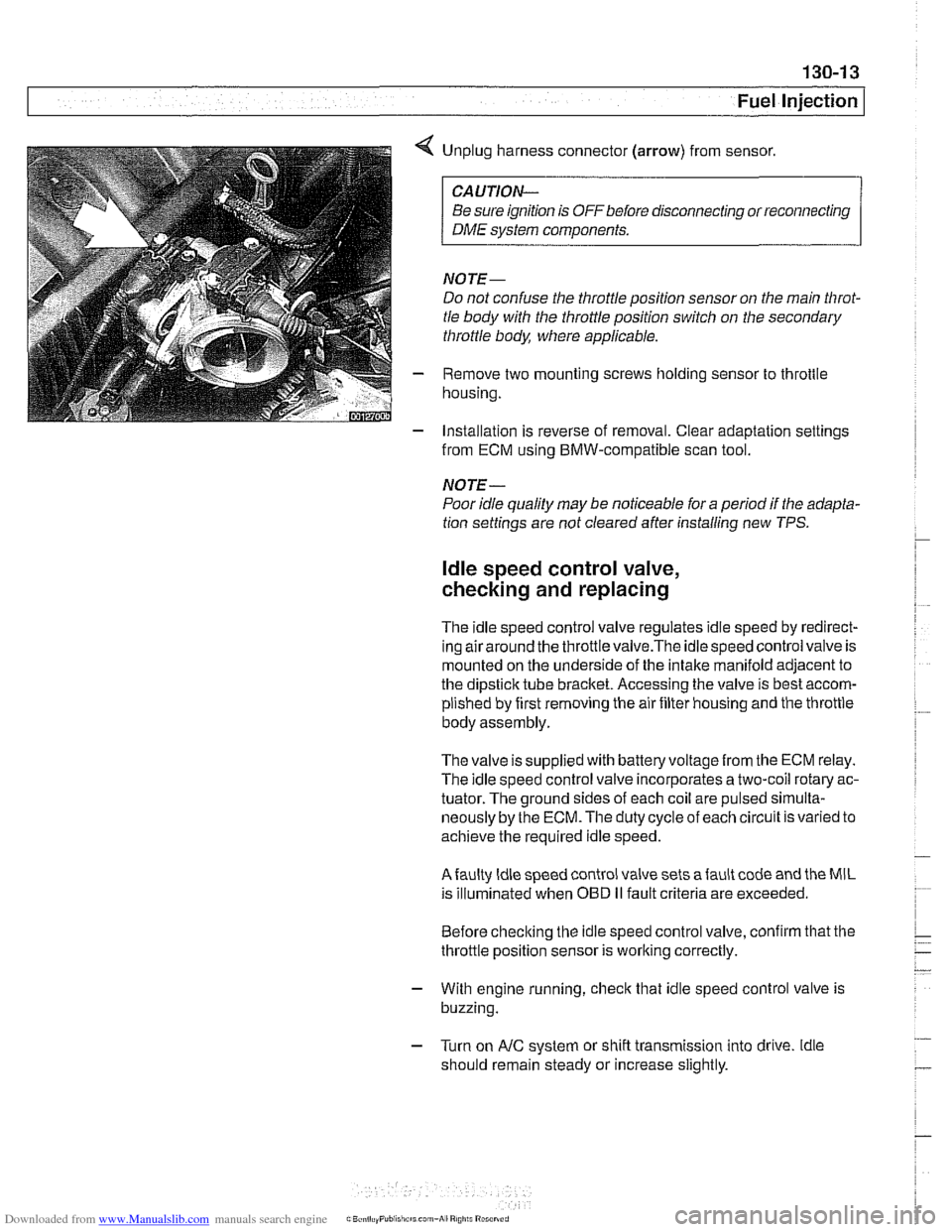
< Unplug harness connector (arrow) from sensor.
CAUTION-
Be sure ignition is OFF before disconnecting or reconnecting
DME system components.
NOTE-
Do not confuse the throttle position sensor on the main Nirot-
tle body with the throttle position switch on the secondary
throttle body, where applicable.
- Remove two mounting screws holding sensor to throttle
housing.
- Installation is reverse of removal. Clear adaptation settings
from ECM using BMW-compatible scan tool.
NOTE-
Poor idle quality may be noticeable for a period if the adapta-
tion settings are not cleared after installing new TPS.
ldle speed control valve,
checking and replacing
The idle speed control valve regulates idle speed by redirect-
inq airaround the throttlevalve.The idlespeed control valve is
mounted on the underside of the intake manifold adjacent to
the dipstick tube bracket. Accessing the valve is best accom-
plished by first removing the air filter housing and the throttle
body assembly.
The valve issupplied with
batteryvoltagefrom the ECM relay.
The idle speed control valve incorporates a two-coil rotary ac-
tuator. The ground sides of each coil are pulsed
sirnulta-
neously by the ECM. The duty cycle of each circuit is varied to
achieve the required idle speed.
Afaulty ldle speed control valve sets afault code and the MIL
is illuminated when
OED II fault criteria are exceeded.
Before checking the idle speed control valve, confirm that the
throttle position sensor is working correctly.
- With engine running, check that idle speed control valve is
buzzing.
- Turn on AIC system or shift transmission into drive. ldle
should remain steady or increase slightly.
Page 404 of 1002
Downloaded from www.Manualslib.com manuals search engine
Fuel Injection
- If idle speed valve is not buzzing, or if idle decreases when
AIC is turned on, stop engine and disconnect harness con-
nector from idle speed valve.
connector
CAUTION-
Be sure ignition is OFFbefore disconnecting or reconnecting
DME system components.
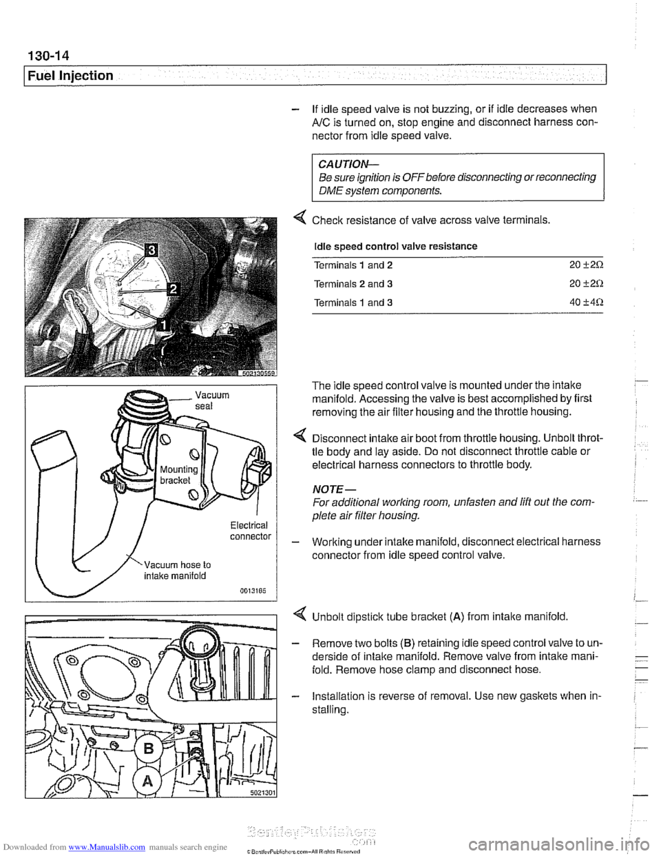
Checlc resistance of valve across valve terminals.
Idle speed control valve resistance
Terminals
1 and 2 20 i-2Q
Terminals 2 and 3 20 C2Q
Terminals 1 and 3 40 C4Q
The idle speed control valve is mounted under the intake
manifold. Accessing the valve is best accomplished by first
removing the air filter housing and the throttle housing.
< Disconnect intake air boot from throttle housing. Unbolt throt-
tle body and lay aside. Do not disconnect throttle cable or
electrical harness connectors to throttle body.
NOTE-
For additional worlcing room, unfasten and lift out the com.
plete air filter housing.
- Working under intake manifold, disconnect electrical harness
connector from idle speed control valve.
Unbolt dipstick tube
bracket (A) from intalte manifold.
- Remove two bolts (B) retaining idle speed control valve to un-
derside of intalte manifold. Remove valve from intalte mani-
fold. Remove hose clamp and disconnect hose.
- Installation is reverse of removal. Use new gaskets when in-
stalling.
Page 406 of 1002
Downloaded from www.Manualslib.com manuals search engine
I Fuel Injection
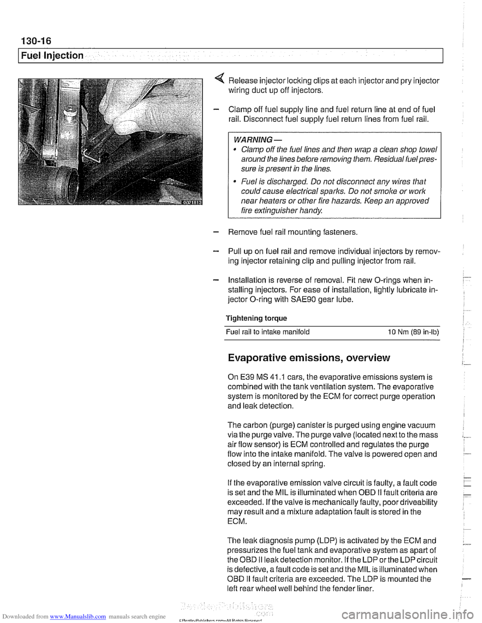
Release injector locking clips at each injector and pry injector
wiring duct up off injectors.
Clamp off fuel supply line and fuel return line at end of fuel
rail. Disconnect fuel supply fuel return lines from fuel rail.
WARNING -
Clamp off the fuel lines and then wrap a clean shop towel
around the lines before removing them. Residual
fuelpres-
sure is present in the lines.
Fuel is discharged. Do not disconnect any wires that
could cause electrical
sparks. Do not smoke or work
near heaters or other fire hazards. Keep an approved
I fire extinguisher handy. I
- Remove fuel rail mounting fasteners
- Pull up on fuel rail and remove individual injectors by remov-
ing injector retaining clip and pulling injector from rail.
- Installation is reverse of removal. Fit new O-rings when in-
stalling injectors. For ease of installation, lightly lubricate in-
jector O-ring with
SAE9O gear lube.
Tightening torque Fuel rail to
intake manifold 10 Nm (89 in-lb)
Evaporative emissions, overview
On E39 MS 41 .I cars, the evaporative emissions system is
combined with the tank ventilation system. The evaporative
system is monitored by the ECM for correct purge operation
and leak detection.
The carbon (purge) canister is purged using engine vacuum
via the
purgevalve.The purgevalve (located nextto the mass
airflow sensor) is ECM controlled and regulates the purge
flow into the intake manifold. The valve is powered open and
closed by an internal spring.
If the evaporative emission valve circuit is faulty, a fault code
is set and the MIL is illuminated when OBD
II fault criteria are
exceeded. If the valve is mechanically faulty, poor driveability
may result and a mixture adaptation fault is stored in the
ECM.
The leak diagnosis pump (LDP) is activated by the ECM and
pressurizes the fuel tank and evaporative system as apart of
theOED I1 leakdetection monitor. If the LDP orthe LDP circuit
is defective, afault code is set and the MIL is illuminated when
OBD
I1 fault criteria are exceeded. The LDP is mounted the
left rear wheel well behind the fender liner.
Page 409 of 1002
Downloaded from www.Manualslib.com manuals search engine
Fuel Injection I
- As an alternative, harness connector housing can be sepa-
rated so that electrical
checlts can be made from backof con-
nector.
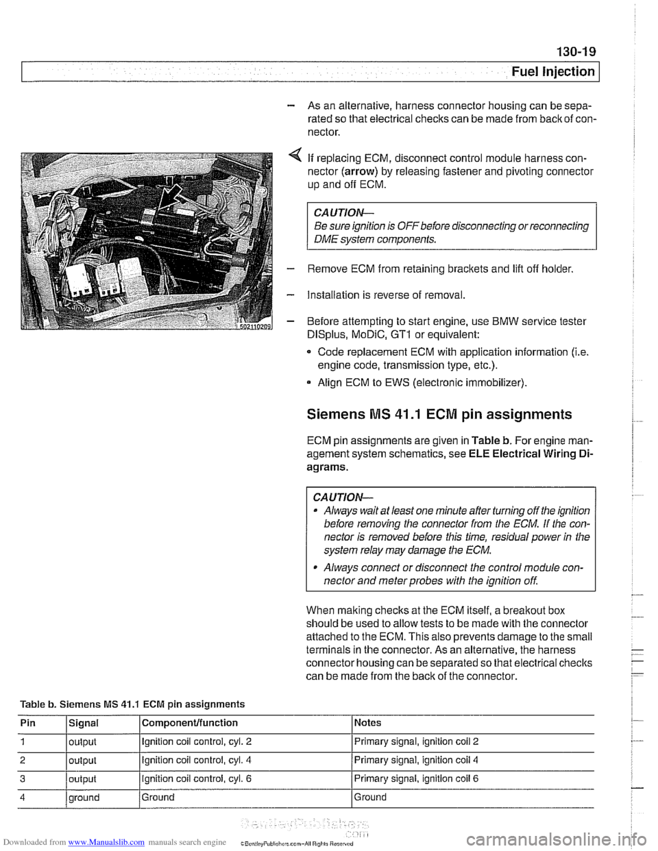
4 If replacing ECM, disconnect control module harness con-
nector (arrow) by releasing fastener and pivoting connector
up and
off ECM.
CAUTION-
Be sure ignition is OFF before disconnecting or reconnecting
DME system components.
- Remove ECM from retaining brackets and lift off holder.
- Installation is reverse of removal.
- Before attempting to start engine, use BMW service tester
DISplus, MoDiC, GTI or equivalent:
- Code replacement ECM with application information (i.e.
engine code, transmission type, etc.).
Align ECM to EWS (electronic immobilizer).
Siemens MS 41.1 ECM pin assignments
ECM pin assignments are given in Table b. For engine man-
agement system schematics, see ELE Electrical Wiring
Di-
agrams.
CAUTION-
a Always wait at least one minute after turning off the ignition
before removing the connector from the
ECM. If the con-
nector is removed before this time, residual power
in the
system relay may damage the
ECM.
Always connect or disconnect the control module con-
nector and meter probes with the ignition
off
When malting checks at the ECM itself, a breakout box
should be used to allow tests to be made with the connector
attached to the ECM. This also prevents damage to the small
terminals in the connector. As an alternative, the harness
connector housing can be separated so that electrical checlts
can be made from the back of the connector.
Table b. Siemens MS
41.1 ECM pin assignments
Pin
1
2
3
4
Signal
output
output
output
qround Componenfffunction
Ignition coil control, cyl. 2
Ignition coil control, cyl. 4
ignition coil control, cyl. 6
Ground Notes
Primary signal,
ignition
coil 2
Primary signal, ignition coil 4
Primary signal, ignition coil 6
Ground
Page 413 of 1002
Downloaded from www.Manualslib.com manuals search engine
- -.
Fuel Injection
SIEMENS MIS 42.0 AND 43.0
When system faults are detected, a diagnostic trouble code
(DTC) is stored in the engine control module (ECM). The MIL
also illuminates
if an emissions-related fault is detected.
When faults arise, or
if the malfunction indicator lamp (MIL) is
illuminated, begin troubleshooting by connecting BMW ser-
vice tester
DISplus, MoDiC, GTI or equivalent scan tool. The
capabilities of OBD
II software has the potential to save hours
of diagnostic time and to help avoid incorrect component re-
placement and possible damage to system components.
CAUTION-
* The tests in this section may set fault codes (DTCs) in tlie
ECM and illuminate the MIL. After all testing is completed,
access and clear DTC fault
memory using an OBD I/ or
BMW compatible scan tool. See
OBD On-Board Diag-
nostics.
Only use a
dgital multimeter for electrical tests.
Relay positions can vary. Be sure to confirm
relayposi-
tion by identifying the wiring in the socket using the wir-
ing diagrams found in
ELE Electrical Wiring
Diagrams.
NOTE-
- OBD I1 fault memory. (including an illuminated MIL! can
only be reset using the special scan tool. Removing the
connector from the ECM or disconnecting the battery will
not erase the fault memory.
The BMW-dedicated 20-pin diagnostic
linlc connector
(DLC) is in the right rear of the engine compartment The
20-pin DLC is discontinued on models after
6/2000.
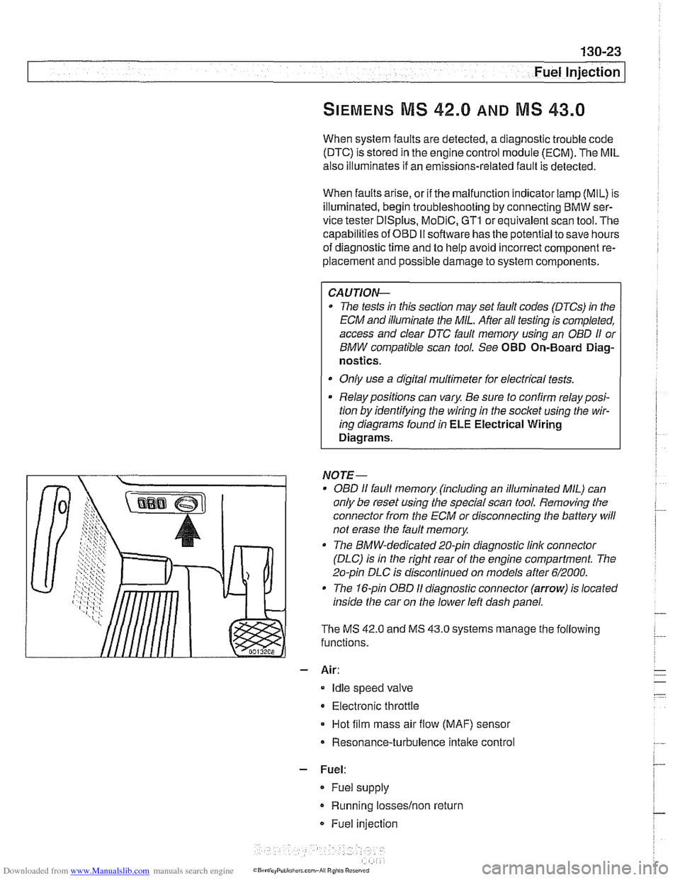
The 1 &pin OBD I1 diagnostic connector (arrow) is located
inside the car on the lower left dash panel.
The MS
42.0 and MS 43.0 systems manage the following
functions.
- Air:
Idle speed valve
Electronic throttle
Hot film mass air flow (MAF) sensor
Resonance-turbulence intake control
- Fuel:
* Fuel supply
Running losseslnon return
Fuel injection
Page 418 of 1002
Downloaded from www.Manualslib.com manuals search engine
130-28
Fuel Injection
ECM Relay
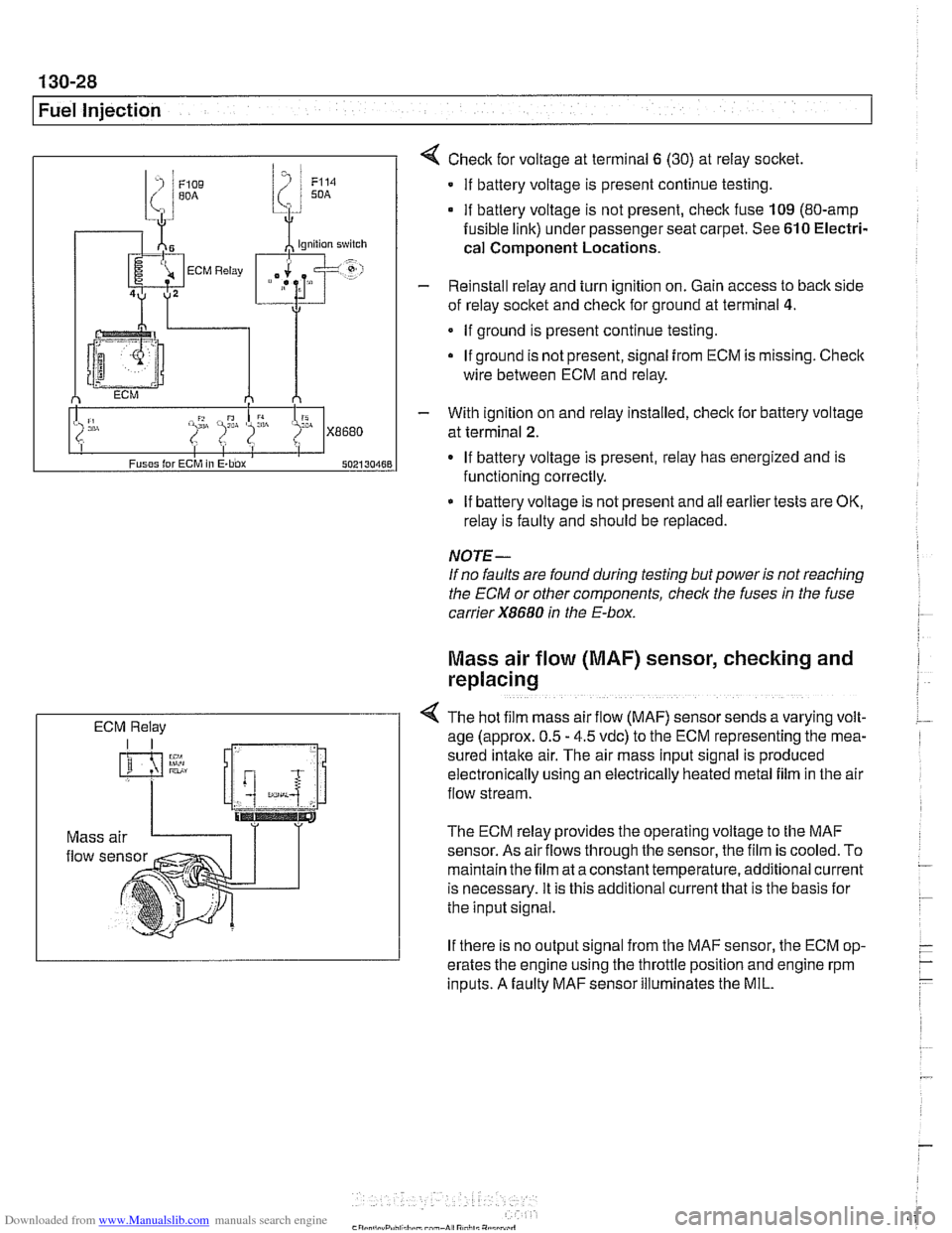
4 Check for voltage at terminal 6 (30) at reiay socket
If battery voltage is present continue testing.
if battery voltage is not present, check fuse 109 (80-amp
fusible link) under passenger seat carpet. See 610 Electri-
cal
Component Locations.
- Reinstall relay and turn ignition on. Gain access to back side
of reiay socket and check for ground at terminal
4.
If ground is present continue testing.
If ground is not present, signal
from ECM is missing. Check
wire between ECM and relay.
- With ignition on and reiay installed, check lor battery voltage
at terminal
2.
If battery voltage is present, relay has energized and is
functioning correctly.
If battery voltage is not present and
ail earlier tests are OK,
relay is faulty and should be replaced.
NOTE-
If no faults are found during testing but power is not reaching
the ECM or other components, check the fuses
in the fuse
carrier
X8680 in the E-box.
Mass air flow (MAF) sensor, checking and
replacing
4 The hot f~lm mass air flow (MAF) sensor sends a varying volt-
age (approx. 0.5 - 4.5 vdc) to the ECM representing the mea-
sured
Intake air. The alr mass input signal is produced
electron~caily uslng an electrically heated metal fllm in the air
flow stream.
The ECM relay provides the operating voltage to the MAF
sensor. As air
flows through the sensor, the film is cooled. To
maintain the film at a constant temperature, additional current
is necessary. It is this additional current that is the basis lor
the input signal.
If there is no output signal from the MAF sensor, the ECM op-
erates the engine using the throttle position and engine rpm
inputs. A faulty MAF sensor illuminates the MIL.