Cylinder BMW 540i 1999 E39 Workshop Manual
[x] Cancel search | Manufacturer: BMW, Model Year: 1999, Model line: 540i, Model: BMW 540i 1999 E39Pages: 1002
Page 501 of 1002
Downloaded from www.Manualslib.com manuals search engine
170-5
Radiator and Cooling System
Fan switch calibration (M52, M62 engine)
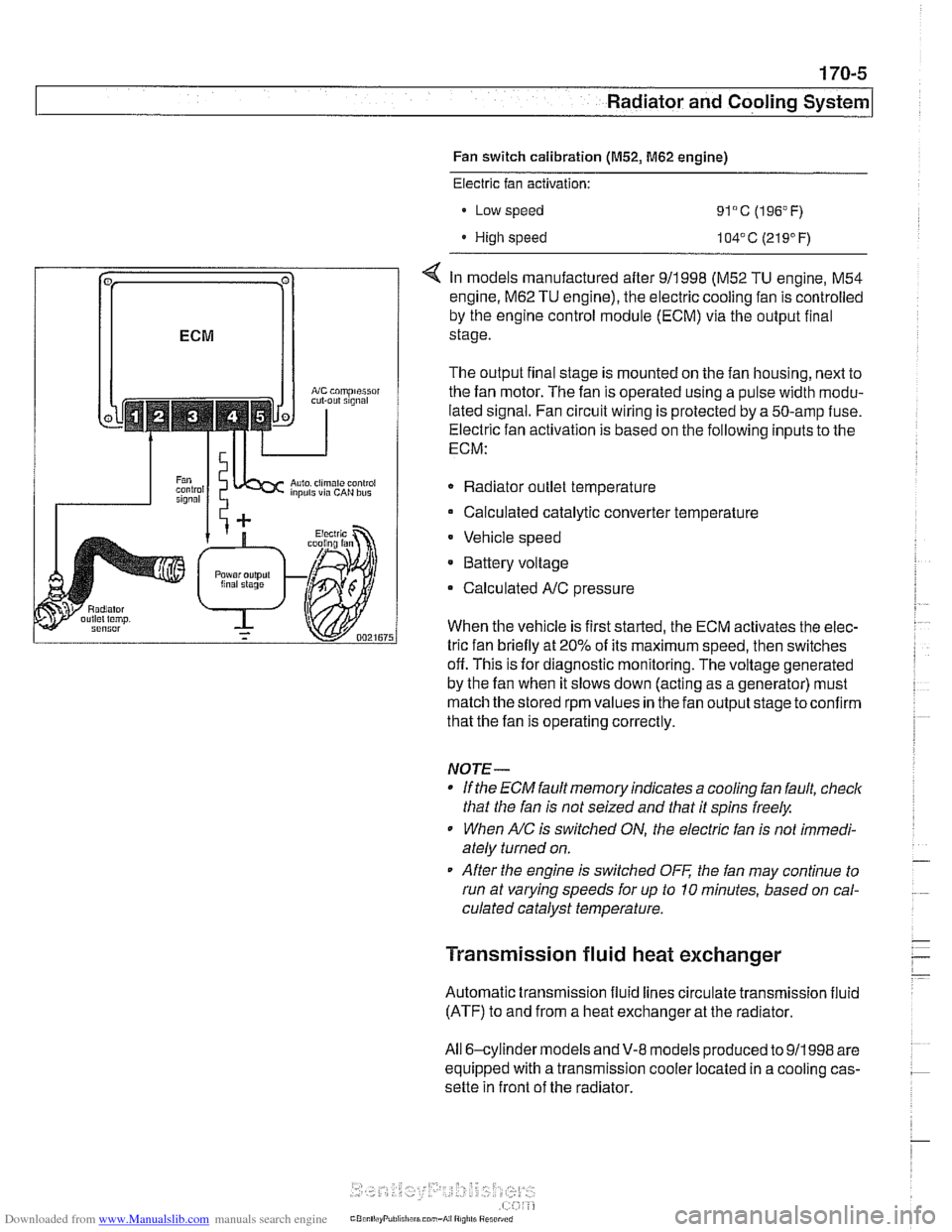
coniprairoi OUt rlgnal
Auto. ciimilte ~ontioi inpuls via CAN bus
Electric fan activation:
Low speed
91°C (196°F)
High speed 104' C (21 9' F)
< In models manufactured after 911998 (M52 TU engine, M54
engine.
M62 TU engine), the electric cooling fan is controlled
by the engine control module (ECM) via the output final
stage.
The output final stage is mounted on the fan housing, next to
the fan motor. The fan is operated using a pulse width modu-
lated signal. Fan circuit wiring is protected by a 50-amp fuse.
Electric fan activation is based on the following inputs to the
ECM:
Radiator outlet temperature
Calculated catalytic converter temperature
Vehicle speed
* Battery voltage
Calculated
A/C pressure
When the vehicle is first started, the ECM activates the elec-
tric fan briefly at 20% of its maximum speed, then switches
off. This is for diagnostic monitoring. The voltage generated
by the fan when it slows down (acting as a generator) must
match the stored rpm values in the fan output stage toconfirm
that the fan is operating correctly.
NOTE-
If the ECM fault memory indicates a cooling fan fault, check
that the fan is not seized and that it spins freely.
When
A/C is switched ON, the electric fan is not immedi-
ately turned on.
After the engine is switched
OFF the fan may continue to
run at varying speeds for up to 10 minutes, based on cal-
culated catalyst temperature.
Transmission fluid heat exchanger
Automatic transmission fluid lines circulate transmission fluid
(ATF) to and from a heat exchanger at the radiator.
All 6-cylinder
models andV-8 models produced to 911998 are
equipped with a transmission cooler located in a cooling cas-
sette in front of the radiator.
Page 505 of 1002
Downloaded from www.Manualslib.com manuals search engine
Radiator and Cooling System
Check for cloggedlplugged radiator or coolant passages.
Cooling system pressure test
A cooling system pressure tester is used to test for coolant
leaks, including internal ones. Common sources of internal
coolant leaks are a faulty cylinder head gasket, a
craclted cyl-
inder head, or a cracked engine block.
WARNING-
At normal operating temperature the cooling system is pres-
surized. Allow the system to cool before opening. Release
the cap slowly to allow safe release ofpressure.
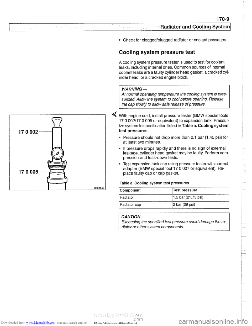
4 With engine cold, install pressure tester (BMW special tools
17 0 002117 0 005 or equivalent) to expansion tank. Pressur-
ize system to specification listed in Table a. Cooling system
test pressures.
Pressure should not drop more than 0.1 bar (1.45 psi) for
at least two minutes.
. If pressure drops rapidly and there is no sign of external
leakage, cylinder head gasket may be faulty. Perform com-
pression and leak-down tests.
Test expansion
tank cap using pressure tester with correct
adapter (BMW special tool 17
0 007 or equivalent). Re-
place faulty cap or cap gasket.
Table a. Cooling system test pressures
0021663 I Component l~est pressure
Radiator
11.5 bar (21.75 psi)
Radiator cap
12 bar (29 psi)
CAUTION-
Exceeding the specified test pressure could damage the ra-
diator or other svstem
com~onents.
Page 506 of 1002
Downloaded from www.Manualslib.com manuals search engine
170-1 0
I Radiator and Cooling System
Combustion chamber leak test
- If you suspect that combustion chamber pressure is leaking
into the cooling system past the cylinder head gasket, use an
exhaust gas analyzer to test the vapors rising from the cool-
ant at the expansion tank.
CAUTIO&
Use an extension tube above the reservoir neclc to main-
tain distance between the top of the coolant and the gas
analyzer
nozzle. The gas analyzer is easily damaged if it is
allowed to inhale liquid coolant.
* While running engine to checlc for causes of overheat-
ing, observe coolant temperature carefully in order to
avoid engine damage.
Thermostat
If the engine overheats or runs too cool and no other cooling
system tests indicate trouble, the thermostat may be faulty.
In
V-8 models and 6-cvlinder models nroduced afler 911 998
(M52TU or M54 eng'ne), rheelecrricaily heated rhermostal IS
mon tored by [he OBD II diagnostlc software The fault may ic
in the DME software or hardware, or it may lie in the wiring to
the thermostat. See
OED On-Board Diagnostics.
Coolant, draining and filling
(6-cylinder models)
WARNING -
Allow the cooling system to cool before opening or draining
the cooling system.
- Raise front of car and support safely.
WARNING -
Make sure the car is stable and well supported at all times.
Use a professional automotive lift
orjack stands designed for
the purpose. A floor jack is not adequate support.
- Remove splash shield from under engine.
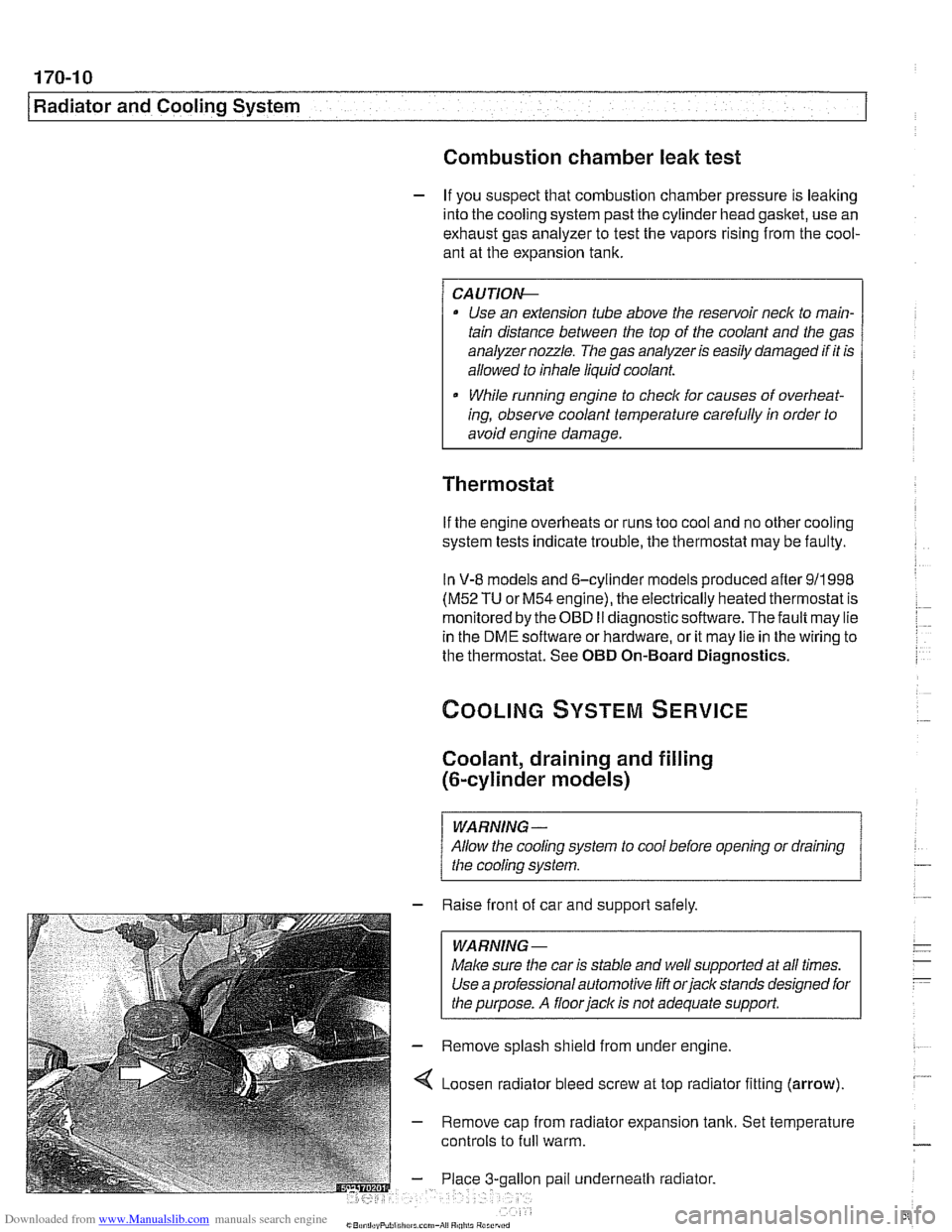
4 Loosen radiator bleed screw at top radiator fitting (arrow).
- Remove cap from radiator expansion tank. Set temperature
controls to
full warm.
gallon pail underneath radiator.
Page 507 of 1002
Downloaded from www.Manualslib.com manuals search engine
170-1 1
Radiator and Cooling system/
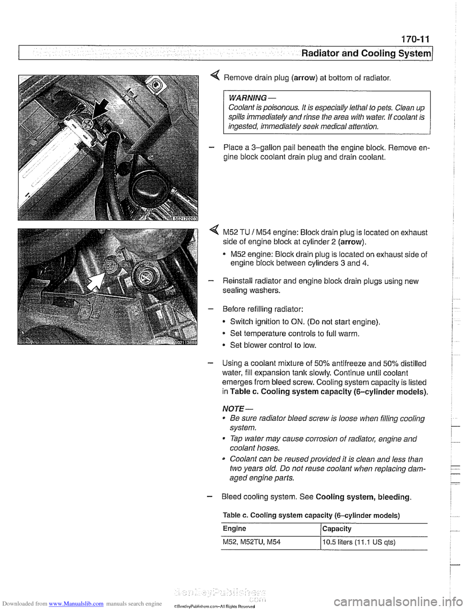
4 Remove drain plug (arrow) at bottom of radiator.
Coolant is poisonous. It is especially lethal to pets. Clean up
spills immediately and rinse the area with
wate,: If coolant is
- Place a 3-gallon pail beneath the engine block. Remove en-
gine block coolant drain plug and drain coolant.
< M52 TU 1 M54 engine: Bloclc drain plug is located on exhaust
side of engine block at cylinder
2 (arrow).
M52 engine:
Bloclc drain plug is located on exhaust side of
engine
bloclc between cylinders 3 and 4.
- Reinstall radiator and engine block drain plugs using new
sealing washers.
- Before refilling radiator:
Switch ignition to
ON. (Do not start engine).
Set temperature controls to full warm.
Set blower control to low.
- Using a coolant mixture of 50% antifreeze and 50% distilled
water, fill expansion tank slowly. Continue until coolant
emerges from bleed screw. Cooling system capacity is listed
in Table c. Cooling system capacity (6-cylinder models).
NOTE-
Be sure radiator bleed screw is loose when filling cooling
system.
Tap water may cause corrosion of radiator, engine and
coolant hoses.
Coolant can be reusedprovided it is clean and less than
two years old. Do not reuse coolant when replacing dam-
aged engine parts.
- Bleed cooling system. See Cooling system, bleeding
Table c. Cooling system capacity (6-cylinder models)
Engine Capacity
M52, M52TU, M54
10.5 liters (1 1.1 US qls)
Page 512 of 1002
Downloaded from www.Manualslib.com manuals search engine
170-1 6
I Radiator and Cooling System
- Remove fan and fan shroud mounting fasteners. Slide fan
and fan shroud downward to remove.
- Reinstallation is reverse of removal.
Thermostat, removing and installing
(M52 engine)
The coolant thermostat is installed in a housing at the front of
the engine.
- Drain coolant from radiator and engine block. See Coolant,
draining and filling (6-cylinder models).
WARNING -
Allow the cooling system to cool before opening or draining
the system.
- Remove mechanical cooling fan and fan shroud. See Me-
chanical (viscous clutch) cooling fan, removing and in-
stalling.
- Disconnect coolant hoses from thermostat housing.
- Remove thermostat housing from front of engine.
- Remove thermostat. Note thermostat direction and orienta-
tion before removing.
- Installation is reverse of removal, noting the following:
- Use new O-ring and gasket(s) when installing thermostat
and housing.
NOTE-
Some thermostats have a direction arrow or vent hole near
the edge. Install the thermostat so that either the arrow or
hole are at the top.
Fill system with coolant as described in Coolant, draining
and filling (6-cylinder models).
CAUTION-
Be sure to reconnect ground wire@) at thermostat housing
mounting bolt, where applicable.
Page 513 of 1002
Downloaded from www.Manualslib.com manuals search engine
Radiator and Cooling systeml
Tightening torques
Block drain plug to block 25 Nm
(18
it-lb)
Coolant hose clamp (32 - 48 2.
5 Nm (22 in-lb)
mm hose diameter)
Radiator drain plug to radiator
2-3Nm(l8-27in-lb)
Thermostat housing to cylinder
head 10 Nm (89 in-lb)
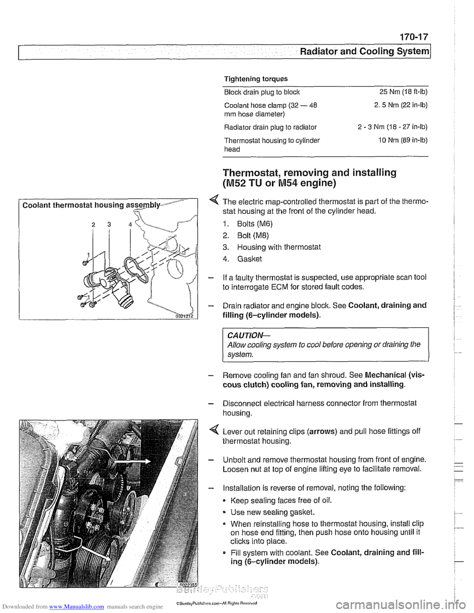
I Coolant thermostat housing assmbly- - I
Thermostat, removing and installing
(M52 TU or M54 engine)
4 The electric map-controlled thermostat is part of the thermo-
stat housing at the front of the cylinder head.
1. Bolts (M6)
2 Bolt (ME)
3. Housing with thermostat
4. Gasket
- If a faulty thermostat is suspected, use appropriate scan tool
to interrogate
ECM for stored fault codes.
- Drain radiator and engine block. See Coolant, draining and
filling (6-cylinder models).
CAUTION-
Allow cooling system to cool before opening or draining the
system.
- Remove cooling fan and fan shroud. See Mechanical (vis-
cous clutch) cooling fan, removing and installing.
- Disconnect electrical harness connector from thermostat
housina.
4 Lever out retaining clips (arrows) and pull hose fittings off
thermostat housing.
- Unbolt and remove thermostat housing from front of engine.
Loosen nut at top of engine lifting eye to facilitate removal.
- Installation is reverse of removal, noting the following:
Keep sealing faces free of oil.
* Use new sealing gasket.
When reinstalling hose to thermostat housing, install clip
on hose end fitting, then push hose onto housing until it
clicks into place.
Fill system with coolant. See Coolant, draining and fill-
ing (6-cylinder models).
Page 514 of 1002
Downloaded from www.Manualslib.com manuals search engine
Tightening torques Block drain plug to block
25 Nm (18 ft-lb)
Radiator drain plug to radiator 2 - 3 Nm (18 - 27 in-lb)
Thermostat housing to
cylinder head 10 Nm (89 in-lb)
Thermostat, removing and installing
(V-8 models)
The electrically-heated thermostat is an integral parl of the
thermostat housing. The operation of the thermostat is moni-
tored by the engine control module (ECM).
- If a faulty thermostat is suspected, use appropriate scan tool
to interrogate ECM for stored fault codes.
- Drain radiator and engine block. See Coolant, draining and
filling
(V-8 models).
WARNING -
Allow cooling system to cool before opening or draining the
system.
- Disconnect mass air flow (MAF) sensor electrical harness
connector. Remove air intake duct together with MAF sensor.
- Remove mechanical cooltng fan and fan shroud. See Me-
chanical (viscous clutch) cooling fan, removing and
in-
stalling.
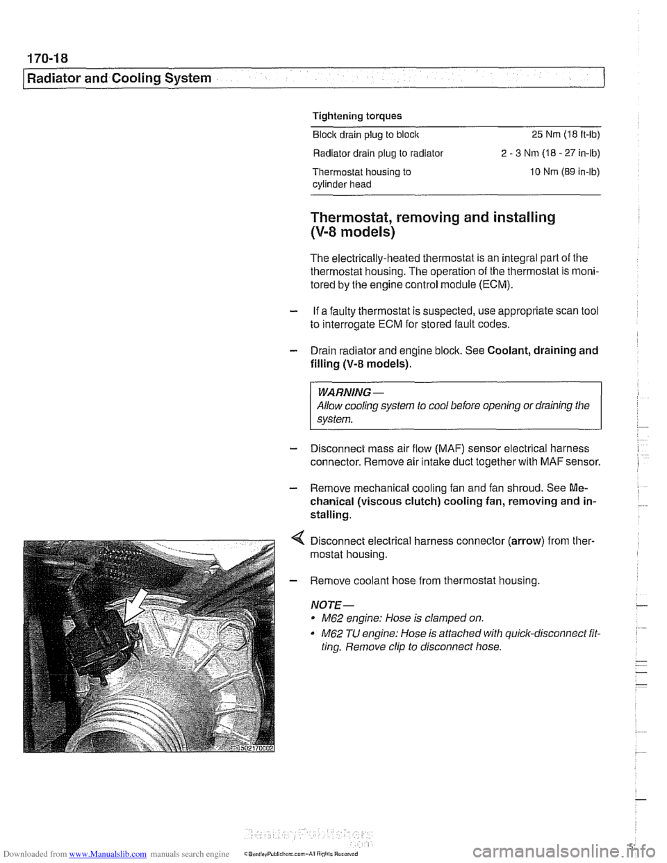
Disconnect electrical harness connector (arrow) from ther-
mostat housing.
Remove coolant hose from thermostat housing.
NOTE-
M62 engine: Hose is clamped on.
M62 TU engine: Hose is attached with quick-disconnect fit.
ting. Remove clip to disconnect hose.
Page 515 of 1002
Downloaded from www.Manualslib.com manuals search engine
170-1 9
Radiator and Cooling System
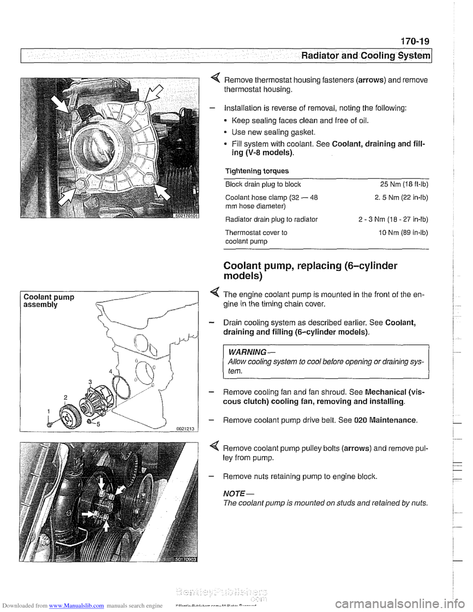
Coolant pump Remove thermostat housing fasteners
(arrows) and remove
thermostat housing.
Installation is reverse of removal, noting the following:
- Keep sealing faces clean and free of oil.
Use new sealing gasket.
Fill system with coolant. See Coolant, draining and fill-
ing
(V-8 models).
Tightening torques
Block drain plug to block 25 Nm (18 it-lb)
Coolant hose clamp (32
- 48 2. 5 Nm (22 in-lb)
mm hose diameter)
Radiator drain plug to radiator 2
- 3 Nm (18 - 27 In-lb)
Thermostat cover to
coolant pump 10 Nm (89 in-lb)
Coolant pump, replacing (6-cylinder
models)
< The engine coolant pump is mounted in the front of the en-
gine in the timing chain cover.
- Drain cooling system as described earlier. See Coolant,
draining and filling (6-cylinder models).
WARNING-
Allow cooling system to cool before opening or draining sys-
tem.
- Remove cooling fan and fan shroud. See Mechanical (vis-
cous clutch) cooling fan, removing and installing.
- Remove coolant pump drive belt. See 020 Maintenance.
4 Remove coolant pump pulley bolts (arrows) and remove pul-
ley from pump.
- Remove nuts retaining pump to engine block.
NOTE-
The coolant pump is mounted on studs and retained by nuts.
Page 516 of 1002
Downloaded from www.Manualslib.com manuals search engine
.," --
Radiator and Cooling System --- 1
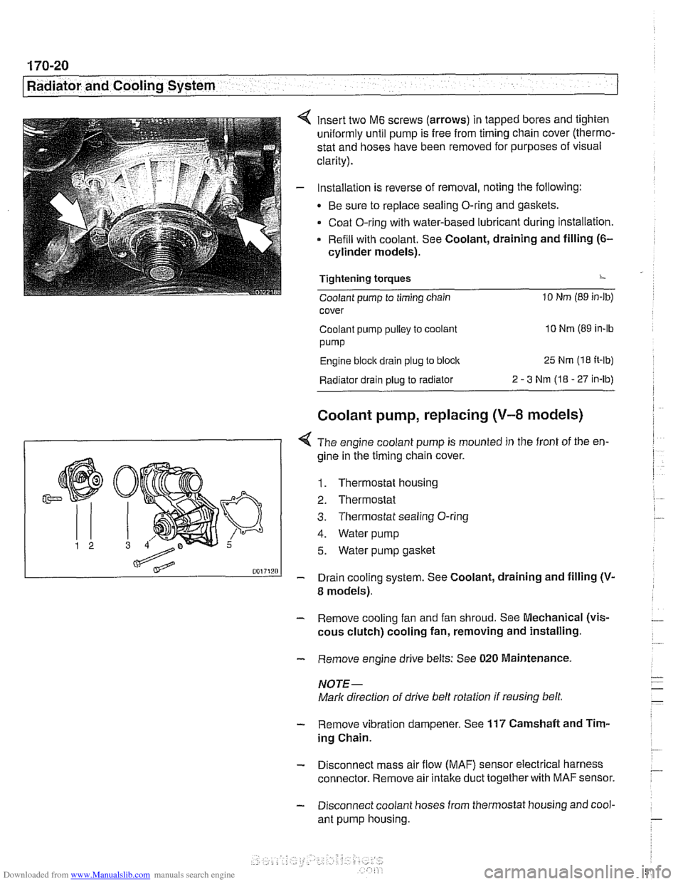
insert two M6 screws (arrows) in tapped bores and tighten
uniformly until pump is free from timing chain cover (thermo-
stat and hoses have been removed for purposes of visual
clarity).
Installation is reverse of removal, noting the following:
Be sure to replace sealing O-ring and gaskets.
Coat O-ring with water-based lubricant during installation.
Refill with coolant. See Coolant, draining and filling
(6-
cylinder models).
Tightening torques
-
Coolant pump to timing chain 10 Nm (89 in-lb)
cover
Coolant pump pulley to coolant
10 Nm (89 in-lb
pump
Engine block drain plug to block 25 Nm (1 8 It-lb)
Radiator drain plug to radiator 2 - 3 Nm (I8 - 27 in-lb)
Coolant pump, replacing (V-8 models)
I 1 < The engine coolant pump is mounted in the front of the en-
gine in ;he timing chain cover.
1. Thermostat housing
2. Thermostat
3. Thermostat sealing O-ring
4. Water pump
5. Water pump gasket
- Drain cooling system. See Coolant, draining and filling (V-
8 models).
- Remove cooling fan and fan shroud. See Mechanical (vis-
cous clutch) cooling fan, removing and installing.
- Remove engine drive belts: See 020 Maintenance.
NOTE-
Mark direction of drive belt rotation if reusing belt,
- Remove vibration dampener. See 117 Camshaft and Tim-
ing Chain.
- Disconnect mass air flow (MAF) sensor electrical harness
connector. Remove air intake duct together with
MAF sensor.
- Disconnect coolant hoses from thermostat housing and cool-
ant pump housing.
Page 517 of 1002
Downloaded from www.Manualslib.com manuals search engine
Radiator and Coolina ~vsteml
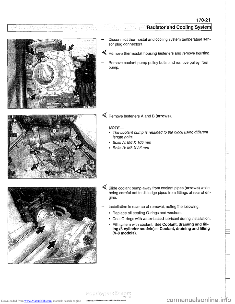
- Disconnect thermostat and cooling system temperature sen-
sor plug connectors.
4 Remove thermostat housing fasteners and remove housing.
- Remove coolant pump pulley bolts and remove pulley from
pump.
Remove fasteners A and B (arrows).
NOTE-
* The coolant pump is retained to the block using different
length bolts.
0 Bolts A: M6 X 105 mm
0 Bolts 8: M6 X 35 mm
Slide coolant pump away from coolant pipes (arrows) while
being careful not to dislodge pipes from fittings at rear of en-
gine.
- Installation is reverse of removal, noting the following:
Replace all sealing O-rings and washers.
Coat O-rings with water-based lubricant during installation.
Fill system with coolant. See Coolant, draining and fill-
ing (6-cylinder models) or Coolant, draining and filling
(V-8 models).