turn BMW 540i 1999 E39 Owner's Guide
[x] Cancel search | Manufacturer: BMW, Model Year: 1999, Model line: 540i, Model: BMW 540i 1999 E39Pages: 1002
Page 146 of 1002
Downloaded from www.Manualslib.com manuals search engine
. .- --
Cylinder Head Removal and Installation
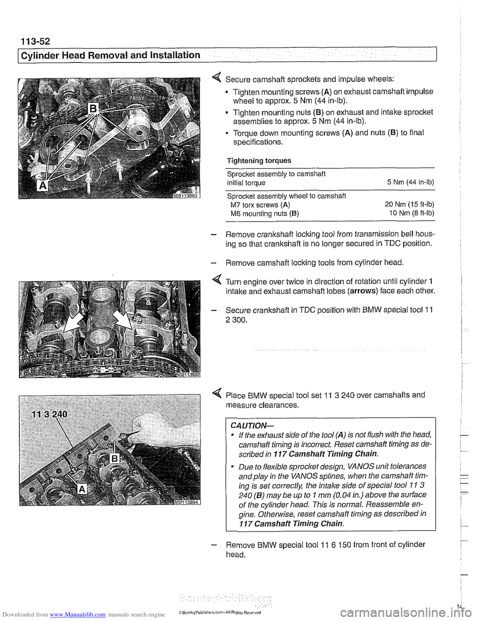
Secure camshaft sprockets and impulse wheels:
Tighten mounting screws
(A) on exhaust camshaft impulse
wheel to approx.
5 Nm (44 in-lb).
Tighten mounting nuts
(8) on exhaust and intake sprocket
assemblies to approx.
5 Nm (44 in-lb).
Torque down mounting screws (A) and nuts (B) to final
specifications.
Tightening torques
sprocket assembly to camshaft
initial torque
5 Nm (44 in-lb)
Sprocket assembly
wheel to camshaft
M7 torx screws (A) 20 Nm (15 ft-lb)
M6 mounting nuts (5) 10 Nm (8 ft-lb)
- Remove crankshaft locking tool from transmission bell hous-
ing so that crankshaft is no longer secured in
TDC position.
- Remove camshaft locking tools from cylinder head.
4 Turn engine over twice in direction of rotation until cylinder 1
intake and exhaust camshaft lobes (arrows) face each other.
- Secure crankshaft in TDC position with BMW special tool 11
2 300.
4 Place BMW special tool set 11 3 240 over camshafts and
measure clearances.
CAUTION-
- If the exhaust side of the tool (A) is not flush with tlie head,
camshaft timing is incorrect Reset camshaft timing as de-
scribed in
117 Camshaft Timing Chain.
* Due to flexible sprocket design, VANOS unit tolerances
and play in the VANOS splines, when the camshaft tim-
ing is set correctly, the intake side of special tool
11 3
240 (6) may be up to 1 mm (0.04 in.) above the surface
of the cylinder head. This is normal. Reassemble en-
gine.
Othe~lise, reset camshaft timing as described in
11 7 Camshaft Timing Chain.
- Remove BMW special tool 11 6 150 from front of cylinder
head.
Page 156 of 1002
Downloaded from www.Manualslib.com manuals search engine
. .- --
[Cylinder ~ead Removal and Installation
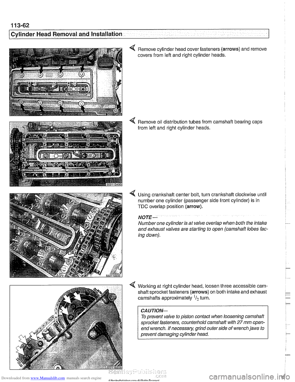
4 Remove cylinder head cover fasteners (arrows) and remove
covers from left and right cylinder heads.
4 Remove oil distribution tubes from camshaft bearing caps
from left and right cylinder heads.
4 Using crankshaft center bolt, turn crankshaft clockwise until
number one cylinder (passenger side front cylinder) is in
TDC overlap position (arrow).
NO JE -
Number one cylinder is at valve overlap when both the intake
and exhaust valves are starting to open (camshaft lobes fac-
ing down).
4 Working at right cylinder head, loosen three accessible cam-
shaft sprocltet fasteners (arrows) on both intake and exhaust
camshafts approximately
'I2 turn.
To prevent valve to piston contact when loosening camshaft
sprocket fasteners, counterhold camshaft with
27 mm open-
end wrench.
If necessary, grind outerside of wrench jaws to
prevent damaging cylinder head.
Page 157 of 1002
Downloaded from www.Manualslib.com manuals search engine
.- --
Cylinder Head Removal and Installation I
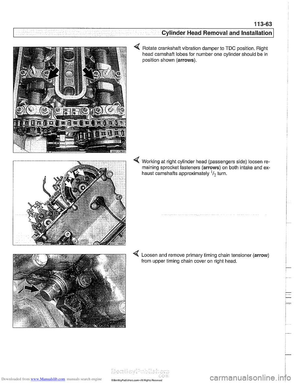
4 Rotate crankshaft vibration damper to TDC position. Right
head camshaft lobes for number one cylinder should be in
position shown (arrows).
Working at right cylinder head (passengers side) loosen re-
maining
sprocltet fasteners (arrows) on both intake and ex-
haust camshafts approximately
'/? turn.
4 Loosen and remove primary timing chain tensioner (arrow)
from upper timing chain cover on right head.
Page 158 of 1002
Downloaded from www.Manualslib.com manuals search engine
1 13-64
Cylinder Head Removal and Installation
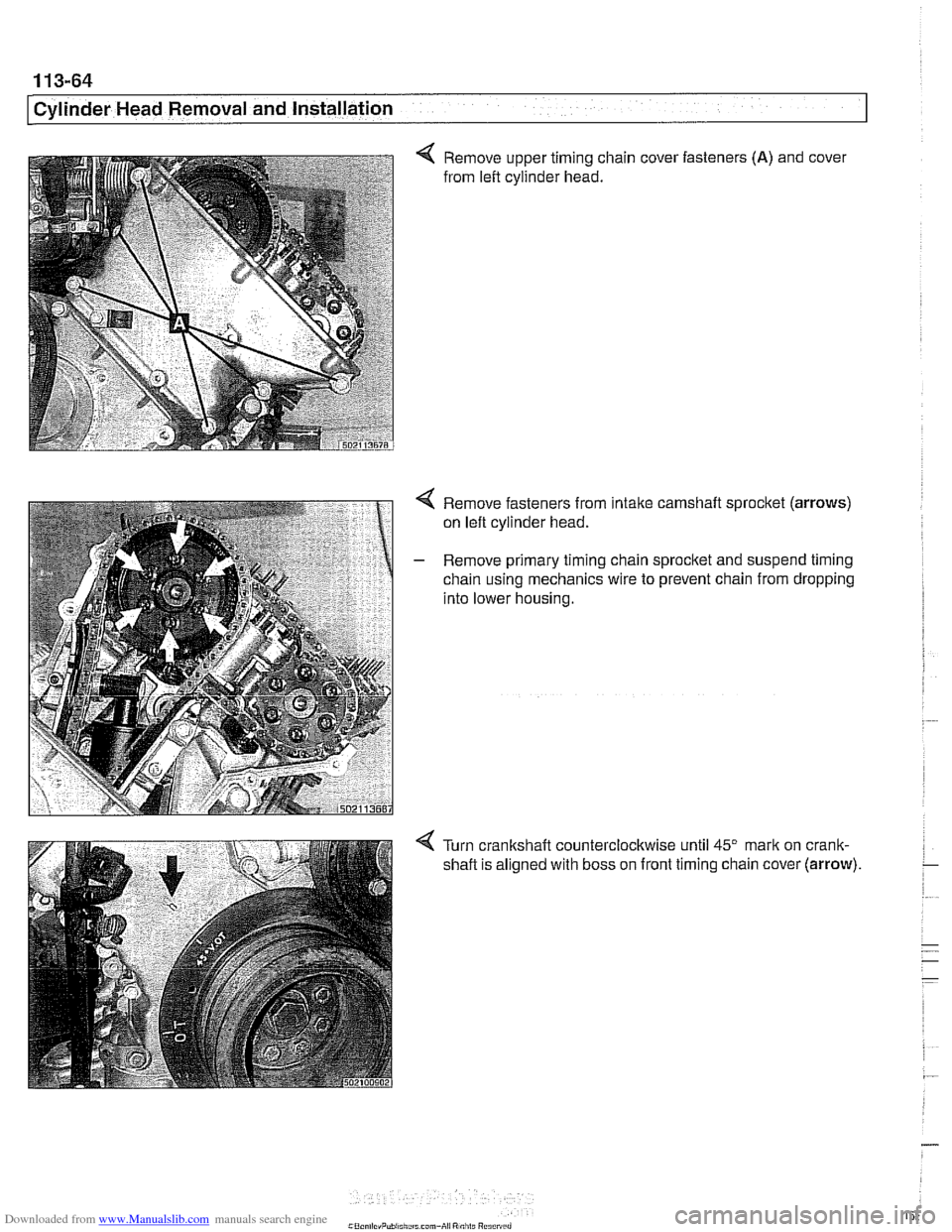
< Remove upper timing chain cover fasteners (A) and cover
from left cylinder head.
4 Remove fasteners from intake camshaft sprocket (arrows)
on left cylinder head.
- Remove primary timing chain sprocket and suspend timing
chain using mechanics wire to prevent chain from dropping
into lower housing.
Turn crankshaft counterclockwise until
45" mark on crank-
shaft is aligned with boss on front timing chain cover
(arrow).
Page 159 of 1002
Downloaded from www.Manualslib.com manuals search engine
1 13-65
Cylinder Head Removal and Installation /
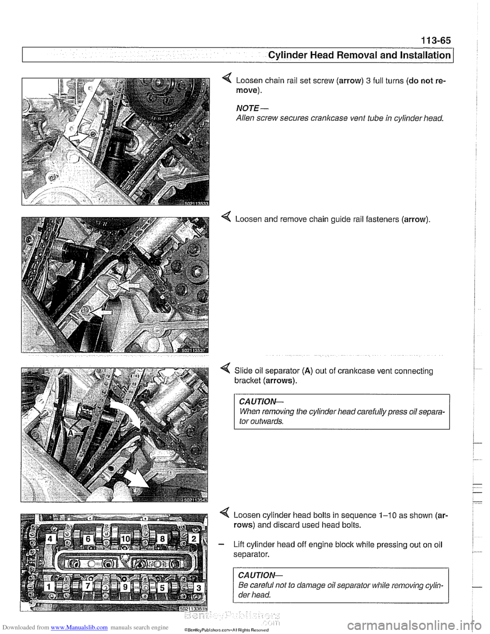
Loosen chain rail set screw (arrow) 3 full
move).
NOTE-
Allen screw secures crankcase vent tube
4 Loosen and turns
(do not re-
in cylinder head.
remove chain guide rail fasteners (arrow).
Slide oil separator
(A) out of cranltcase vent connecting
bracket (arrows).
CAUTIOI\C
When removing the cylinder head carefully press oil separa-
tor outwards.
Loosen cylinder head bolts in sequence
1-10 as shown (ar-
rows) and discard used head bolts.
Lift cylinder head off engine block while pressing out on oil
separator.
CAUTIOI\C
Be careful not to damage oil separator while removing cylin-
der head.
Page 161 of 1002
Downloaded from www.Manualslib.com manuals search engine
1 13-67
Cylinder Head Removal and lnstaKI --
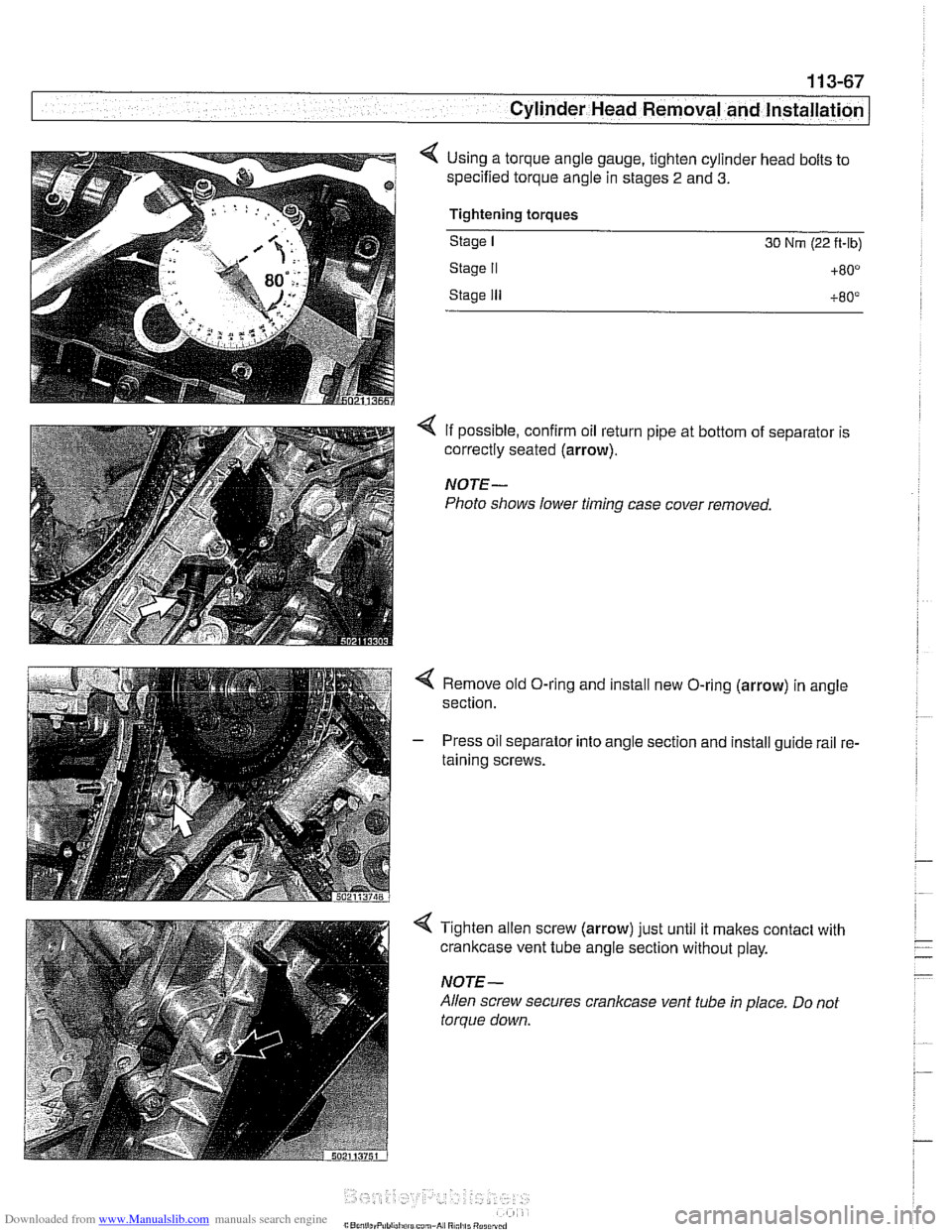
< Using a torque angle gauge, tighten cylinder head bolts to
specified torque angle in stages
2 and 3.
Tightening torques
Stage I 30 Nrn (22 ft-lb)
Stage II +80°
Stage Ill +80°
4 If possible, confirm oil return pipe at bottom of separator is
correctly seated
(arrow).
NOTE-
Photo shows lower timing case cover removed.
< Remove old O-ring and install new O-ring (arrow) in angle
section.
- Press oil separator into angle section and install guide rail re-
taining screws.
4 Tighten allen screw (arrow) just until it makes contact with
crankcase vent tube angle section without play.
NOTE-
Allen screw secures crankcase vent tube in place. Do not
torque down.
Page 163 of 1002
Downloaded from www.Manualslib.com manuals search engine
11 3-69
Cylinder Head Removal and Installation
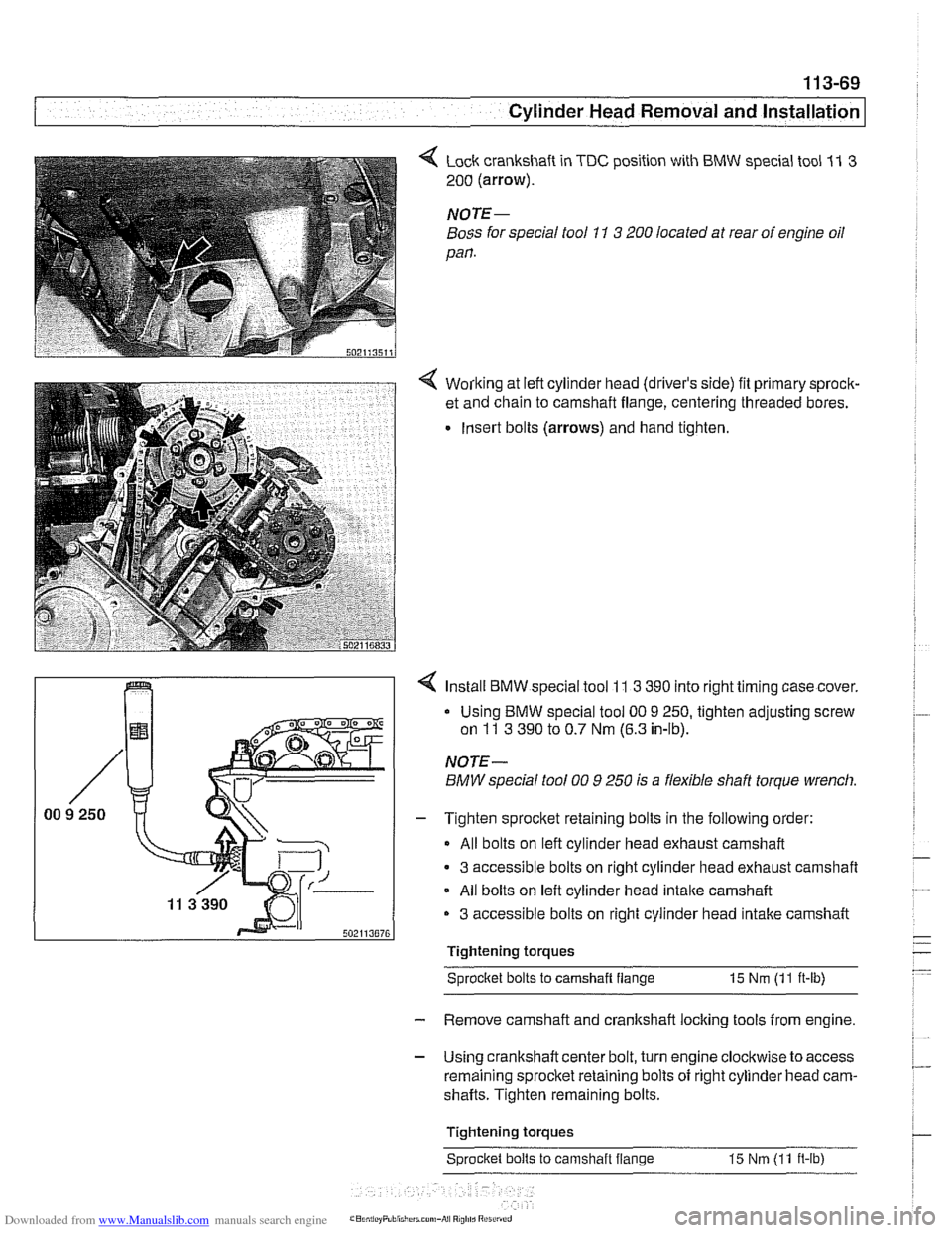
4 Lock crankshaft in TDC position with BMW special tool 11 3
200 (arrow).
NOTE-
Boss for special tool 11 3 200 located at rear of engine oil
pan.
4 Working at left cylinder head (driver's side) fit primary sprock-
et and chain to camshaft flange, centering threaded bores.
Insert bolts (arrows) and hand tighten.
?-I I 4 Install BMW special tool 11 3 390 into right timing case cover.
NOTE-
BMW special tool 00 9 250 is a flexible shaft torque wrench.
I - Tighten sprocket retaining bolts in the following order:
All bolts on left cylinder head exhaust camshaft
3 accessible bolts on right cylinder head exhaust camshaft
All bolts on left cylinder head
intake camshaft
3 accessible bolts on right cylinder head intake camshaft r"".."..7n
Tightening torques
Sprocltet bolts to camshait flange
15 Nm (11 ft-lb)
- Remove camshaft and crankshaft locking tools from engine.
- Using crankshaft center bolt, turn engine clockwise to access
remaining sprocket retaining bolts of right cylinder head cam-
shafts. Tighten remaining bolts.
Tightening torques Sprocket bolts to camshaft flange 15 Nm
(11 ft-lb)
Page 165 of 1002
Downloaded from www.Manualslib.com manuals search engine
. ." . .
I - Cylinder Head Removal - and instard --
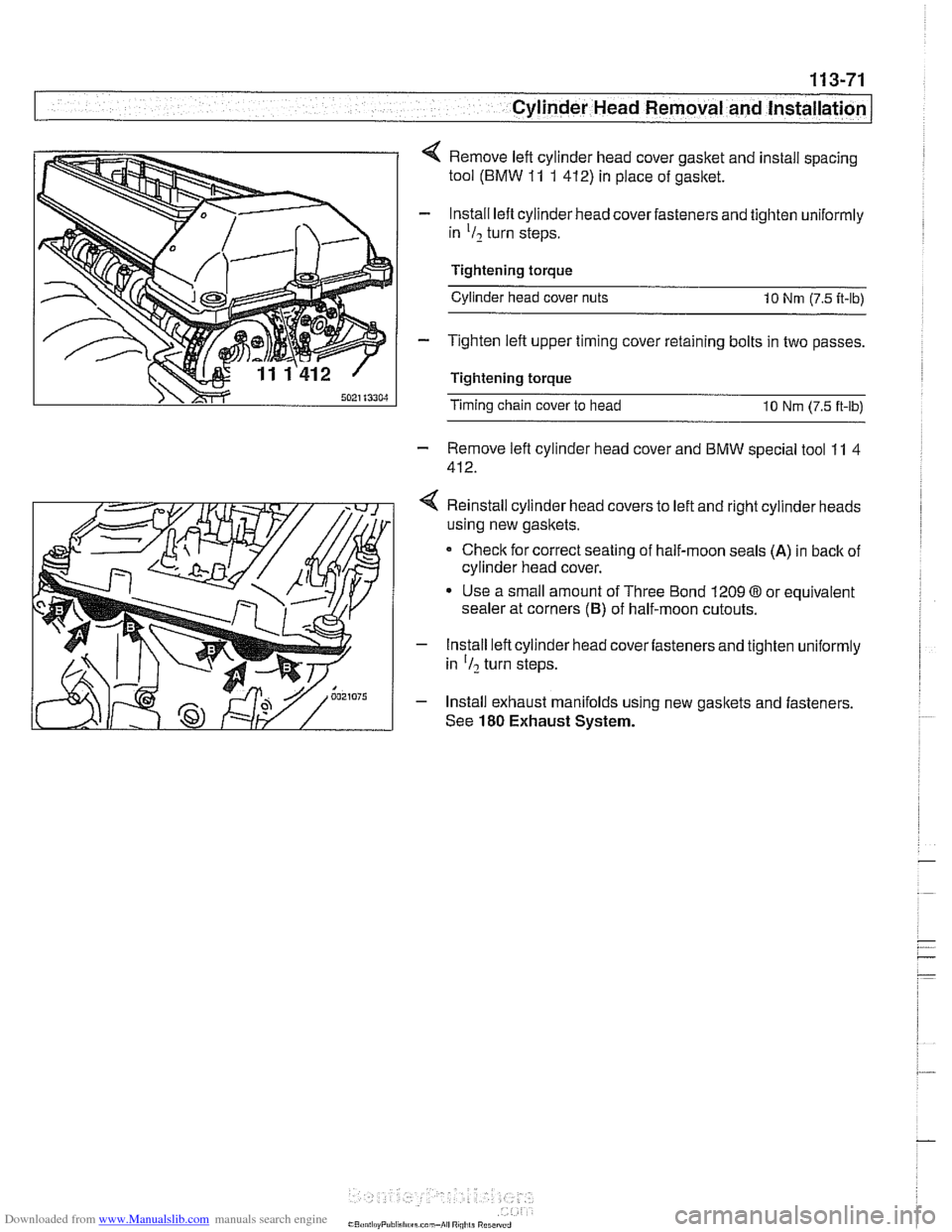
4 Remove left cylinder head cover gasket and install spacing
tool (BMW
11 1 412) in place of gasket.
- lnstall lefl cylinder head cover fasteners and tighten uniformly
in
'I2 turn steps.
Tightening torque Cylinder head cover nuts
10 Nrn (7.5 it-lb)
- Tighten left upper timing cover retaining bolts in two passes.
Tightening torque
Timing chain cover to head 10 Nrn (7.5 ft-lb)
- Remove lefl cylinder head cover and BMW special tool 11 4
412.
4 Reinstall cylinder head covers to left and right cylinder heads
using new gaskets.
Check for correct seating of half-moon seals
(A) in back of
cylinder head cover.
Use a small amount of Three Bond 1209
03 or equivalent
sealer at corners
(6) of half-moon cutouts.
- Install left cylinder head cover fasteners and tighten uniformly
in
'I? turn steps.
- Install exhaust manifolds using new gaskets and fasteners.
See
180 Exhaust System.
Page 167 of 1002
Downloaded from www.Manualslib.com manuals search engine
11 3-73
Cylinder Head Removal and Installation /
1
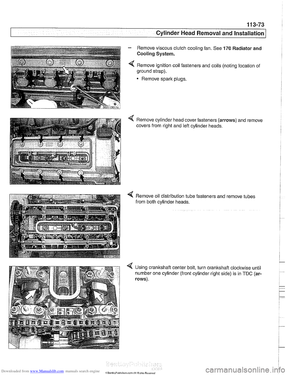
- Remove viscous clutch cooling fan. See 170 Radiator and
i Cooling System. i i I 4 Remove ignition coil fasteners and coils (noting location of
~ ground strap).
1
Remove sparlc plugs.
i
Remove oil distribution tube fasteners and remove tubes
from both cylinder heads.
4 Using crankshaft center bolt, turn crankshaft cloclcwise until
number one cylinder (front cylinder right side) is in
TDC (ar-
rows).
Page 168 of 1002
Downloaded from www.Manualslib.com manuals search engine
11 3-74
Cylinder Head Removal and Installation
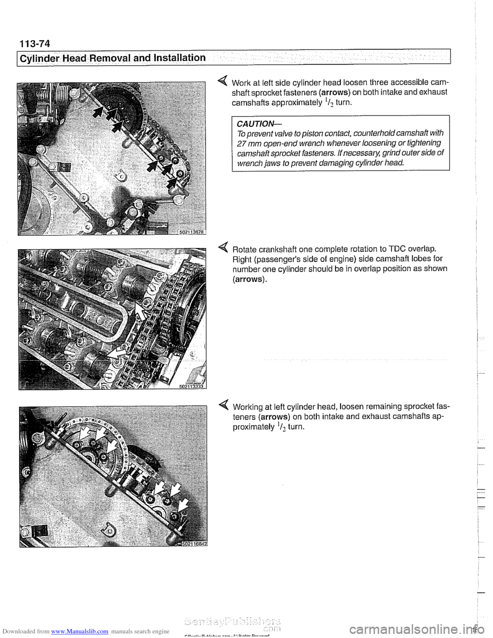
4 Work at left side cylinder head loosen three accessible cam- shaft sprocket fasteners (arrows) on both intake and exhaust
camshafts approximately
'I2 turn.
Toprevent valve
topiston contact, counterholdcamshaft with
27 mm open-end wrench whenever loosening or tightening
camshaft sprocket fasteners. If
necessarq! grind outer side of
wrench jaws to prevent damaging cylinder head.
4 Rotate crankshaft one complete rotation to TDC overlap.
Right (passenger's side of engine) side camshaft lobes for
number one cylinder should be in overlap position as shown
(arrows).
4 Working at left cylinder head, loosen remaining sprocket fas-
teners (arrows) on both
intake and exhaust camshafts ap-
proximately
'I2 turn.