turn BMW 540i 1999 E39 Owner's Manual
[x] Cancel search | Manufacturer: BMW, Model Year: 1999, Model line: 540i, Model: BMW 540i 1999 E39Pages: 1002
Page 110 of 1002
Downloaded from www.Manualslib.com manuals search engine
113-16
Cylinder Head Removal and Installation
- Remove secondary timing chain and sprockets:
Remove mounting nuts from front of intake camshaft
sprocket. Remove and label shim.
CAUTION-
Hold the camshaft stationary (at hex on camshaft) when loos-
ening or tightening sprocket mounting fasteners.
Remove mounting nuts from front of exhaust camshaft
sprocket and remove and label thrust washer.
NOTE-
Where applicable, make note of thrust washerpositions. The
thicker
(0.4 mm) washer is mounted outermost.
- Remove secondary sprockets together with camshaft tim-
ing chain from front of camshafts.
CAUTION-
The camshafts must be locledin the TDCposition using the
special service tool as described earlier: The arrows on the
sprockets should not be used to accurately set the engine to
TDC. The tool holds the camshafts parallel to each other and
NOTE-
Do not remove the sprocl
to
Iceep the sproclefs timed to each other:
CAUTIOI\C
The crankshaft must not be allowed to rotate once the cam-
shaft timing chain is removed. The pistons can
contact the
valves.
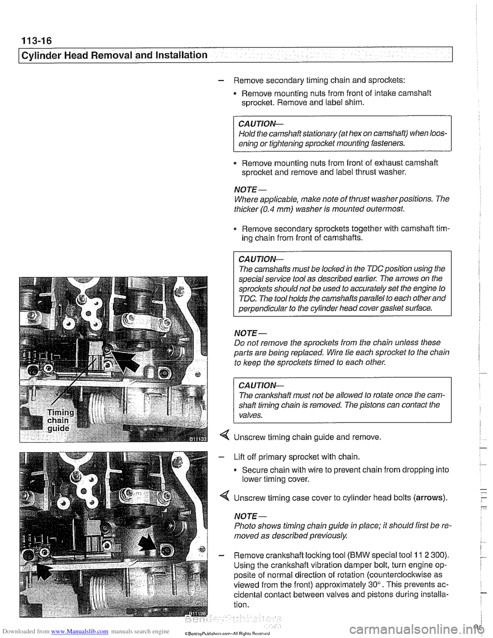
Unscrew timing chain guide and remove.
Lift off primary sprocket with chain.
Secure chain with wire to prevent chain from dropping into
lower timing cover.
Unscrew timing case cover to cylinder head bolts (arrows).
NOTE-
Photo shows timing chain guide in place; it should first be re-
moved as described previously.
Remove crankshaft locking tool
(BMW special tool 11 2 300).
Using the crankshaft vibration damper bolt, turn engine op-
posite of normal direction of rotation (counterclocltwise as
viewed from the front) approximately 30". This prevents ac-
cidental contact between valves and pistons during installa-
tion.
Page 114 of 1002
Downloaded from www.Manualslib.com manuals search engine
--
Cylinder Head Removal and Installation
NOTE-
BMW special tool 11 4 220 is an adjustable primary chain
tensioner and simulates the function of the hydraulic
tensioner.
- Check that elongated holes in primary sprocket are now cen-
tered to bolt holes in camshaft and chain is free of slack. If
not, reposition sprocket to chain and reinstall.
- lnstall secondary timing chain guide and secondary chain
tensioner. Tighten mounting bolts (tensioner remains locked
down for now using
BMW special tool 11 3 292).
- Install cylinder identification trigger plate to front of intake
camshaft with studs.
- Install spacer to front of intake camshaft.
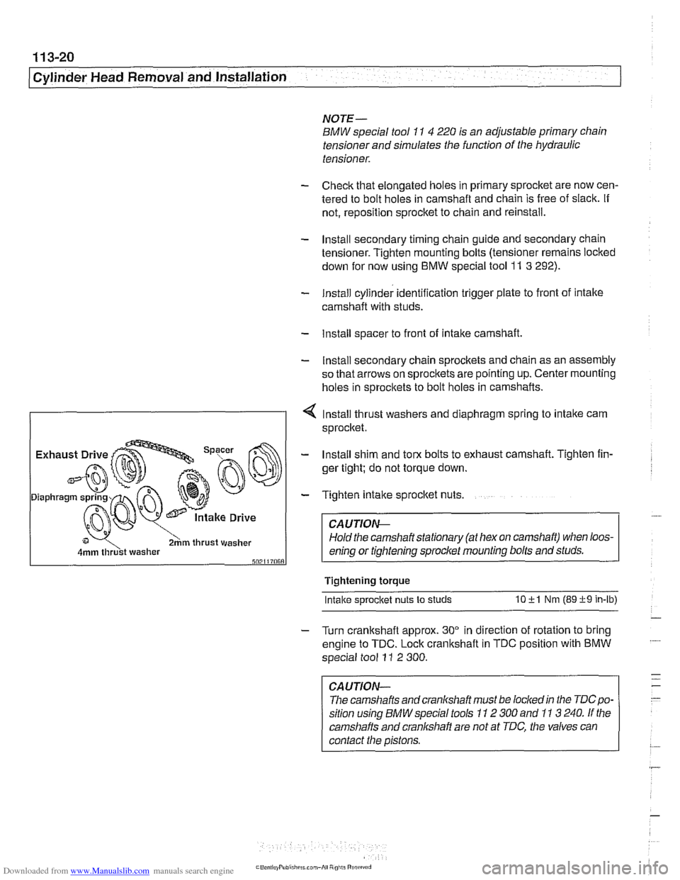
- Install secondary chain sprockets and chain as an assembly
so that arrows on sprockets are pointing up. Center mounting
holes in sprockets to bolt holes in camshafts.
4 lnstall thrust washers and diaphragm spring to intake cam
sprocket.
I 2hm thrust washer I
- Install shim and torx bolts to exhaust camshaft. Tighten fin-
ger tight; do not torque down.
- Tighten intake sprocket nuts.
CA UTIOG
Hold the camshaft stationary (at hex on camshaft) when loos-
enino or tiahtenino sorocket mounting bolts and studs.
Tightening torque
Intake s~rocket nuts to studs 10 +l Nm (89 +9 in-lb)
- Turn crankshaft approx. 30" in direction of rotation to bring
engine to TDC. Lock crankshaft in TDC position with BMW
special tool
11 2 300.
CAUTION-
The camshafts andcranlshaft must be lockedin the TDCpo-
sition using BMW special tools 11 2 300 and 11 3 240. If the
camshafts and cranl(shaft are not at TDC, the valves can
contact the pistons.
Page 116 of 1002
Downloaded from www.Manualslib.com manuals search engine
1 13-22
Cylinder Head Removal and Installation
CYLINDER HEAD REMOVAL AND
~NSTALLATION (M52 TU AND N154
ENGINES)
WARNING -
Due to risk ofpersonal injur)c be sure the engine is cold be-
fore
beqinning the removal procedure.
Cylinder head removal and installation is a time consuming
repair procedure requiring multiple special service tools.
Read the entire procedure before beginning the repair.
This topic includes the following procedures:
* Cylinder head, removing, M52 TU and M54 engines
Cylinder head, installing,
M52 TU and M54 engines
Cylinder head, removing,
M52 TU and M54 engines
Allow engine to cool before beginning this procedure.
- Disconnect negative (-) cable from battery.
CAUTION-
Prior to disconnecting the battery, read the battery discon-
nection cautions in
001 General Cautions and Warnings.
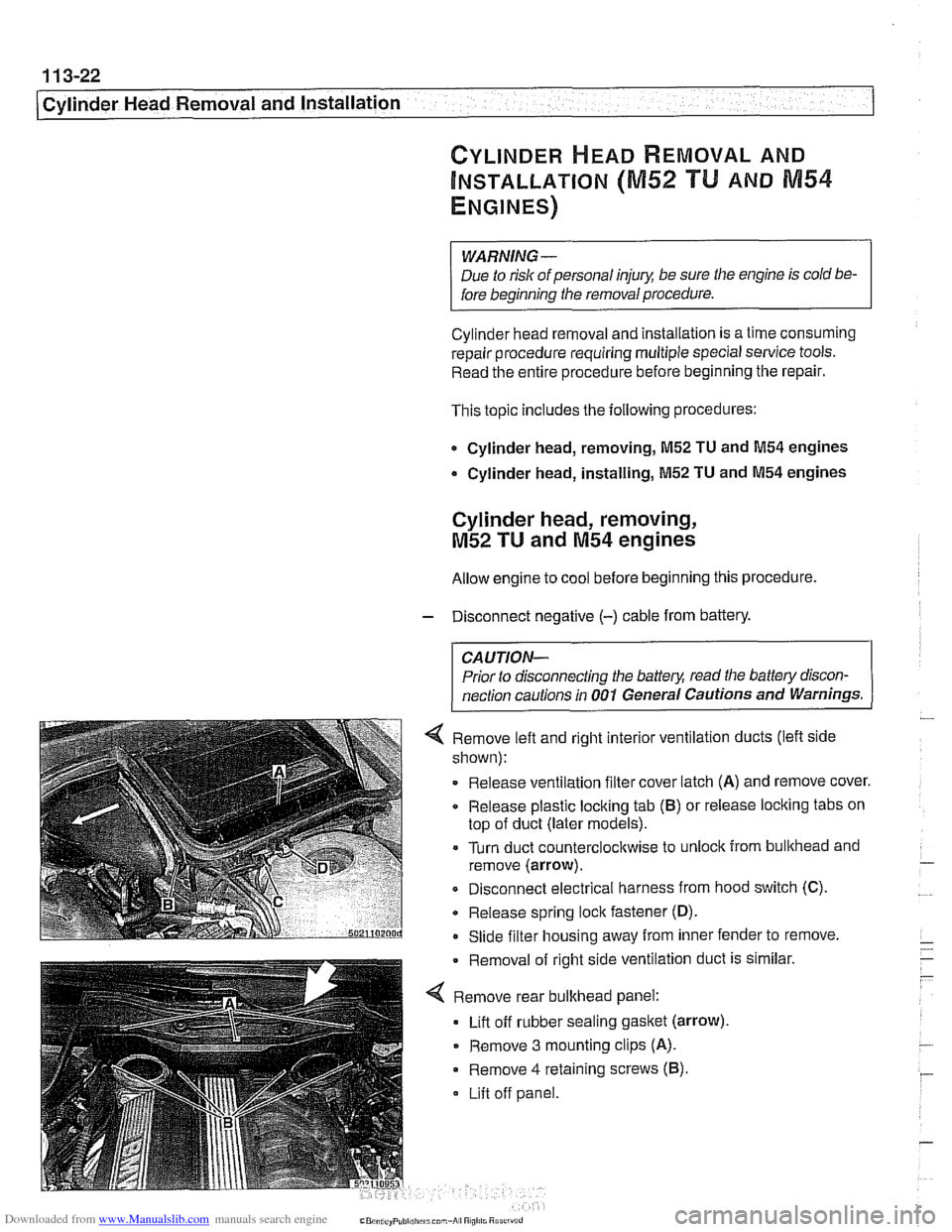
4 Remove left and right interior ventilation ducts (left side
shown):
Release ventilation filter cover latch
(A) and remove cover.
Release plastic locking tab
(6) or release locking tabs on
top of duct (later models).
= Turn duct counterclocltwise to unlock from bullthead and
remove (arrow).
Disconnect electrical harness from hood switch (C).
Release spring lock fastener
(D).
- Slide filter housing away from inner fender to remove.
Removal of right side ventilation
dud
Remove rear bulkhead panel:
Lift off rubber sealing
gasket (arrow)
- Remove 3 mounting clips (A).
Remove 4 retaining screws (6).
Lift off panel.
: is similar
Page 119 of 1002
Downloaded from www.Manualslib.com manuals search engine
11 3-25
Cylinder Head Removal and Installation
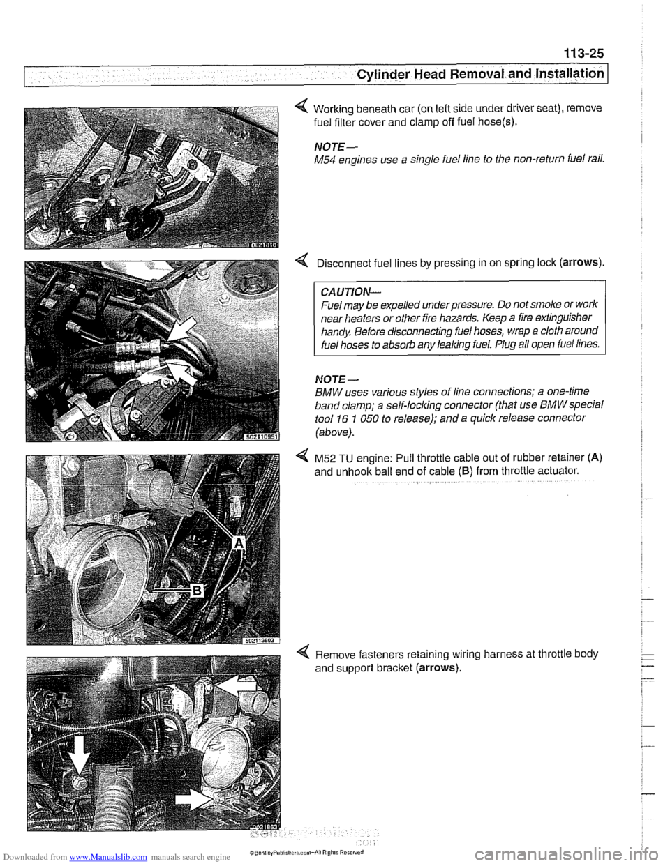
4 Working beneath car (on left side under driver seat), remove
fuel filter cover and clamp
off fuel hose(s).
NOTE-
M54 engines use a single fuel line to the non-return fuel rail.
Disconnect fuel lines by pressing in on spring lock (arrows).
CAUTION--
Fuel may be expelled underpressure. Do not smoke or worlc
near heaters or other fire hazards. Keep a fire extinguisher
handy Before disconnecting fuel hoses, wrap a cloth around
fuel hoses to absorb any leaking fuel. Plug all open fuel lines.
NOJE-
BMW uses various styles of line connections; a one-time
band clamp; a
self-locl(ing connector (that use BMWspecial
tool 16 1 050 to release); and a quick release connector
(above).
4 M52 TU engine: Pull throttle cable out of rubber retainer (A)
and unhook ball end of cable (6) from throttle actuator.
4 Remove fasteners retaining wiring harness at throttle body
and support bracket (arrows).
Page 120 of 1002
Downloaded from www.Manualslib.com manuals search engine
. - --
j Cylinder Head Removal and Installation
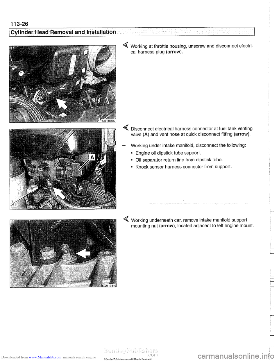
4 Working at throttle housing, unscrew and disconnect electri-
cal harness plug
(arrow).
4 Disconnect electrical harness connector at fuel tank venting
valve
(A) and vent hose at quick disconnect fitting (arrow).
- Working under intake manifold, disconnect the following:
Engine oil dipstick tube support.
Oil separator return line from dipstick tube.
Knock sensor harness connector from support.
4 Working underneath car, remove intake manifold support
mounting nut
(arrow), located adjacent to left engine mount.
Page 131 of 1002
Downloaded from www.Manualslib.com manuals search engine
Cylinder Head Removal and Installation I
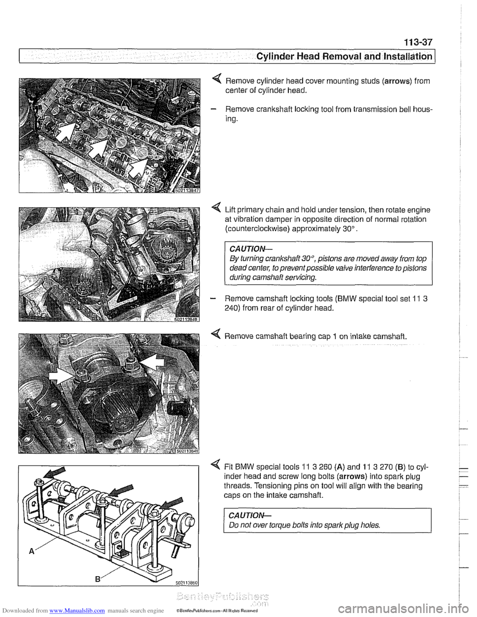
Remove cylinder head cover mounting studs (arrows) from
center of cylinder head.
- Remove crankshaft loclting tool from transmission bell hous-
Ing.
Lift primary chain and hold under tension, then rotate engine
at vibration damper in opposite direction of normal rotation
(counterclocltwise) approximately 30".
CAUTION-
By turning crankshait3O0, pistons are movedaway from top
dead center, to prevent possible valve interference to pistons
during camshaft servicing.
- Remove camshaft loclting tools (BMW special tool set 11 3
240) from rear of cylinder head.
4 Remove camshaft bearing cap 1 on intake camshaft.
4 Fit BMW special tools 11 3 260 (A) and 11 3 270 (B) to cyl-
inder head and screw long bolts (arrows) into spark plug
threads. Tensioning pins on tool will align with the bearing
caps on the
intake camshaft.
CAUJION-
Do not over torque bolts into sparkplug holes.
Page 132 of 1002
Downloaded from www.Manualslib.com manuals search engine
11 3-38
I Cylinder Head Removal and Installation
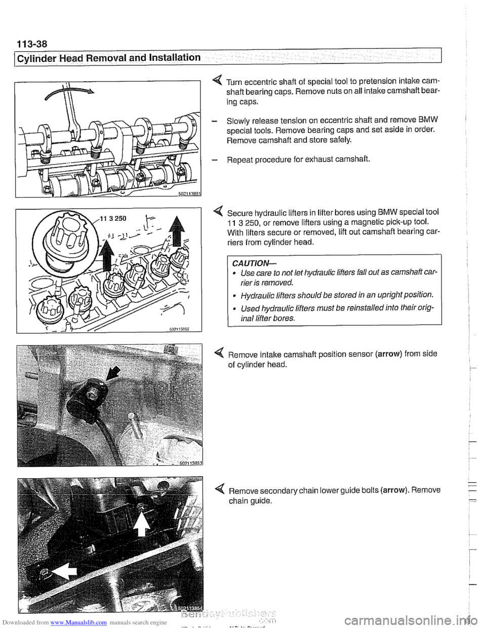
< Turn eccentric shaft of special tool to pretension intake cam-
shaft bearing caps. Remove nuts on all intake camshaft bear-
ing caps.
- Slowly release tension on eccentric shaft and remove BMW
spec~al tools. Remove bearing caps and set as~de in order.
Remove camshaft and store safely.
- Repeat procedure for exhaust camshaft.
4 Secure hydraulic lifters in lifter bores using BMW speclal tool
11 3 250, or remove lifters using a magnetic pick-up tool.
With lifters secure or removed, lift out camshaft bearing car-
riers from cylinder head.
Use care to not let hydraulic lifters fall out as camshaft car-
rier is removed.
Hydraulic lifters should be stored
ln an uprightpositlon.
Used hydraulic lifters must be reinstalled into their orig-
inal lifter bores.
4 Remove intake camshaft position sensor (arrow) from side
of cylinder head.
4 Remove secondary chain lowerguide bolts (arrow). Remove
chain guide.
Page 137 of 1002
Downloaded from www.Manualslib.com manuals search engine
.-
Cylinder Head Removal and Installation
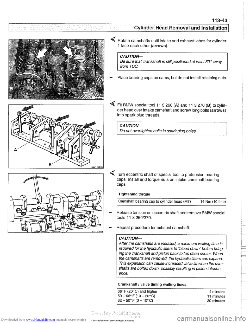
4 Rotate camshafts until intake and exhaust lobes for cylinder
1 face each other (arrows).
CAUTION-
Be sure that cranlcshaft is stillpositioned at least 30" away
from
TDC.
- Place bearing caps on cams, but do not install retaining nuts.
4 Fit BMW special tool 11 3 260 (A) and 11 3 270 (B) to cylin-
der head over intake camshaft and screw long bolts (arrows)
into spark plug threads.
CAUTIOI\C
Do not overtighten bolts in spark plug holes.
Turn eccentric shaft of special tool to pretension
bearing
caps. Install and torque nuts on intake camshaft bearing
caps.
Tightening torque Camshaft bearing
cap to cylinder head (M7) 14 Nm (10 ft-lb)
Release tension on eccentric
shaft and remove BMW special
tools
11 3 2601270.
Repeat procedure for exhaust camshaft.
CAUTION-
After the camshafts are installed, a minimum waiting time is
required for the hydraulic lifters to 'bleed down" before bring-
ing the crankshaft andpiston back to top
deadcenter. When
the camshafts are removed, the hydraulic lifters can expand.
This expansion can cause increased valve lift when the cam-
shafts are bolted down, possibly resulting in piston interfer-
ence.
Crankshaft
I valve timing waiting times
68.F (20°C) and higher 4 minutes
50-68"F(10-20°C) 11 minutes
32-5O0F(O-10°C) 30 minutes
Page 138 of 1002
Downloaded from www.Manualslib.com manuals search engine
11 3-44
I Cylinder Head Removal and Installation
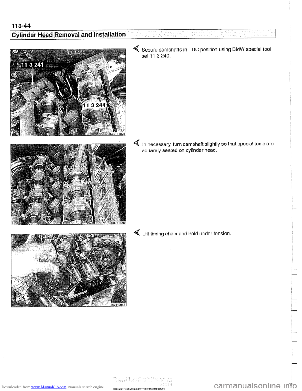
4 Secure camshafts in TDC position using BMW special tool
set
11 3 240.
4 In necessary, turn camshaft slightly so that special tools are
squarely seated on cylinder head.
4 Lift timing chain and hold under tension.
Page 143 of 1002
Downloaded from www.Manualslib.com manuals search engine
-7 Cylinder Head Removal and lnstallat~on -- -- - -
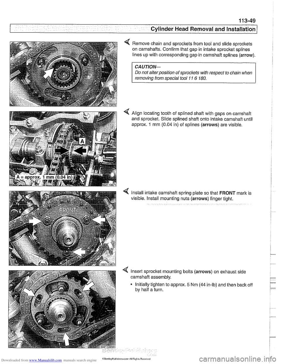
Remove chain and sprockets from tool and slide sprockets
on camshafts. Confirm that gap in intake sprocket splines
lines up with corresponding gap in camshaft splines (arrow).
CAUTIOI\C
Do not alter position of sprockets with respect to chain when
removing
from special tool 11 6 180.
< Align locating tooth of splined shaft with gaps on camshaft
and sprocket. Slide splined shaft onto intake camshaft until
approx.
1 mm (0.04 in) of splines (arrows) are visible.
4 Install intake camshafl spring plate so that FRONT mark is
visible. Install mounting nuts (arrows) finger tight.
Insert sprocket mounting bolts (arrows) on exhaust side
camshaft assembly.
Initially tighten to approx.
5 Nm (44 in-lb) and then back off
by half a turn.