turn BMW 540i 1999 E39 Service Manual
[x] Cancel search | Manufacturer: BMW, Model Year: 1999, Model line: 540i, Model: BMW 540i 1999 E39Pages: 1002
Page 170 of 1002
Downloaded from www.Manualslib.com manuals search engine
1 13-76
Cylinder Head Removal and Installation
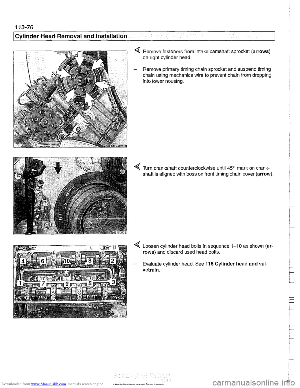
Remove fasteners from intake camshaft sprocket (arrows)
on right cylinder head.
- Remove primary timing chain sprocket and suspend timing
chain using mechanics wire to prevent chain from dropping
into lower housing.
Turn crankshaft counterclockwise until
45" mark on crank-
shaft is aligned with boss on front timing chain cover (arrow)
4 Loosen cylinder head bolts in sequence 1-10 as shown (ar-
rows) and discard used head bolts.
- Evaluate cylinder head. See 116 Cylinder head and val-
vetrain.
Page 174 of 1002
Downloaded from www.Manualslib.com manuals search engine
11 3-80
Cylinder Head Removal and lnstallation
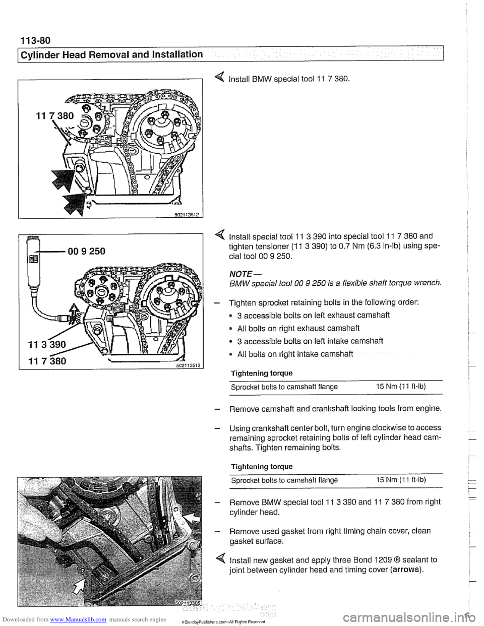
I I 4 Install BMW special tool 11 7 380
4 Install special tool 11 3 390 into special tool 11 7 380 and
tighten tensioner
(1 1 3 390) to 0.7 Nm (6.3 in-lb) using spe-
cial tool 00
9 250.
NOTE-
BMW special tool 00 9 250 is a flexible shaft torque wrench.
- Tighten sprocket retaining bolts in the following order:
3 accessible bolts on left exhaust camshaft
- All bolts on right exhaust camshaft
3 accessible bolts on left intake camshaft
All bolts on right intake camshaft
Tightening torque
Sprocitet bolts to camshaft flange 15 Nm (11 ft-lb)
- Remove camshaft and crankshaft locking tools from engine.
- Using crankshaft center bolt, turn engine clockwise to access
remaining sprocket retaining bolts of left cylinder head cam-
shafts. Tighten remaining bolts.
Tightening torque
Sprocket bolts
to camshaft flange 15 Nm (11 ft-ib)
- Remove BMW special tool 11 3 390 and 11 7 380 from right
cylinder head.
- Remove used gasket from right timing chain cover, clean
gasket surface.
4 Install new gasket and apply three Bond 1209 @sealant to
joint between cylinder head and timing cover
(arrows).
Page 175 of 1002
Downloaded from www.Manualslib.com manuals search engine
Cylinder Head Removal and Installation 1
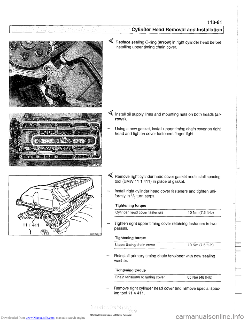
Replace sealing O-ring (arrow) in right cylinder head before
installing upper timing chain cover.
4 Install oil supply lines and mounting nuts on both heads (ar-
rows).
- Using a new gasket, install upper timing chain cover on right
head and tighten cover fasteners finger tight.
4 Remove right cylinder head cover gasket and install spacing
tool
(BMW 11 1 41 1) in place of gasket.
- Install right cylinder head cover fasteners and tighten uni-
formly in
'1, turn steps.
Tightening torque Cylinder head cover fasteners
10 Nm (7.5 ft-lb)
- Tighten right upper timing cover retaining fasteners in two
passes.
I Tightening torque
Upper timing chain cover
10 Nm (7.5 ft-lb)
- Reinstall primary timing chain tensioner with new sealing
washer.
Tightening torque
Chain tensioner to timing cover
65 Nm (48 ft-lb)
- Remove right cylinder head cover and remove special spac-
ingtooi 11 4411.
Page 176 of 1002
Downloaded from www.Manualslib.com manuals search engine
1 13-82
1 Cylinder Head Removal and Installation
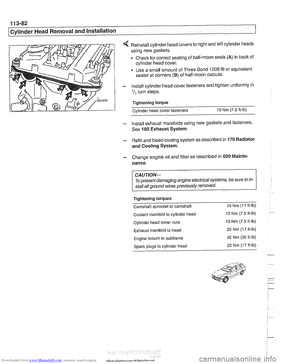
4 Reinstall cylinder head covers to right and left cylinder heads
using new gaskets.
Check for correct seating of half-moon seals
(A) in back of
cylinder head cover.
Use a small amount of Three Bond
1209 8 or equivalent
sealer at corners
(B) of half-moon cutouts.
- Install cylinder head cover fasteners and tighten uniformly in
'I2 turn steps.
Tightening torque Cvlinder head cover fasteners
10 Nm (7.5 It-lb)
- Install exhaust manifolds using new gaskets and fasteners.
See
180 Exhaust System.
- Refill and bleed cooling system as described in 170 Radiator
and Cooling System.
- Change engine oil and filter as described in 020 Mainte.
nance.
CA UTIOW-
To prevent damaging engine electricalsystems, be sure to in-
stall all ground wires previously removed.
Tightening
tOrqUeS
Camshaft sprocket to camshaft 15 Nm (1 1 ft-lb)
Coolant manifold to cylinder head lo Nm (7.5 It-lb)
Cylinder head cover nuts 10 Nm (7.5 ft-lb)
Exhaust manifold to head 22 Nm (17 ft-lb)
Engine mount to subframe 42 Nm (30 ft-lb)
Spark plugs to cylinder head 22 Nm (17 ft-lb)
Page 192 of 1002
Downloaded from www.Manualslib.com manuals search engine
.
Cylinder Head and Valvetrain
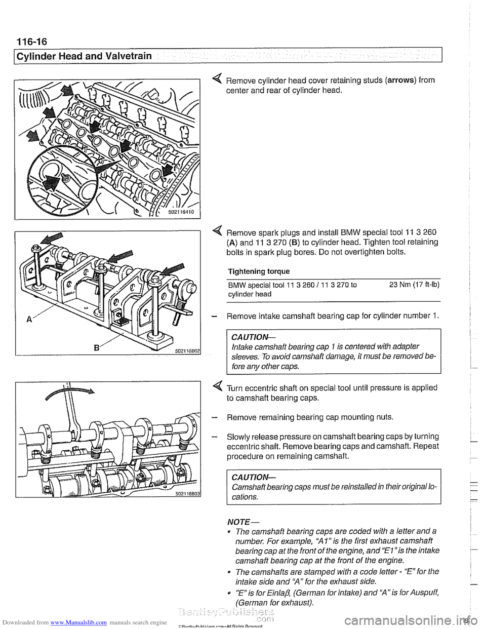
< Remove cylinder head cover retaining studs (arrows) from
center and rear of cylinder head.
< Remove spark plugs and install BMW special tool 11 3 260
(A) and 11 3 270 (6) to cylinder head. Tighten tool retaining
bolts in spark plug bores. Do not overtighten bolts.
Tightening
torque
BMW special tool 11 3 260 I1 1 3 270 to 23 Nm (17 It-lb)
cylinder head
- Remove intake camshaft bearing cap for cylinder number 1.
CA UTIOG
Intake camshaft bearing cap 1 is centered with adapter
sleeves. To avoid
can~sllaft daniage, it must be removed bs-
fore any other caps.
Turn eccentric shaft on special tool until pressure is applied
to camshaft bearing caps.
- Remove remaining bearing cap mounting nuts
- Slowly release pressure on camshaft bearing caps by turning
eccentric shaft. Remove bearing caps and camshaft. Repeat
procedure on remaining camshaft.
CAUTION-
Camshaft bearing caps must be reinstalled in their original lo-
cations.
NOTE-
The camshaft bearing caps are coded with a letter anda
number. For example,
'XI" is the first exhaust camshaft
bearing cap at the front of the engine, and
"El "is the intalce
camshaft bearing cap at the front of the engine.
0 The camshafts are stamped with a code letter - "E" for the
intake side and 'MA" for the exhaust side.
0 "E is for Einlap, (German for intake) and 'XA"is for Auspuff,
(German for exhaust).
Page 200 of 1002

Downloaded from www.Manualslib.com manuals search engine
..--.
I Cylinder Head and Valvetrain - I
4 Lift primary chain and hold under tension, rotate engine
against direction of rotation (counterclockwise) approximate-
ly 30".
To prevent damaging valves while
worlcing on camshafts, no
aistons should be in the TDC position.
- Remove BMW special tool set 1 I 3 240 from rear of cylinder
head.
Remove retaining nuts (arrows) and bearing cap
1 of intake
camshaft.
Intake camshaft bearing cap
1 is centered with adapter
sleeves. To avoid camshaft damage, it must be removed be-
fore anv other caos.
4 Fit BMW special tools 11 3 260 (A) and 11 3 270 (B) to cylin-
der head and screw long bolts (aiiows) into spark plug
threads. Tensioners will align with the bearing caps on the in-
take camshaft.
CA UTION--
Do not over torque bolts into spark plug holes. 1
4 Turn eccentric shaft of special tool to pretension intake carn-
shaft bearing caps. Remove nuts on remaining bearing caps.
- Slowly release tension on eccentric shaft and remove BMW
special tools. Remove bearing caps and set aside in order.
Remove camshaft and store safely.
CA U TIOW-
Camshaft bearing caps must be installed in their original lo-
cations.
Page 203 of 1002
Downloaded from www.Manualslib.com manuals search engine
-- - . .- -,
Cylinder Head and Valvetrain
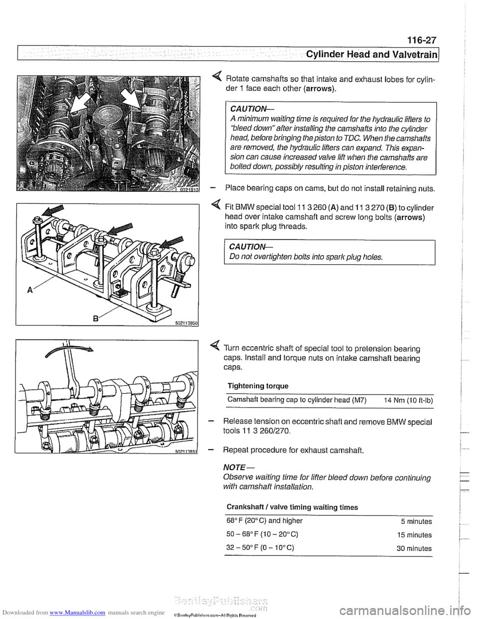
4 Rotate camshafts so that intalte and exhaust lobes for cylin-
der
1 face each other (arrows).
CAUJION-
A minimum waiting time is required for the hydraulic lifters to
'bleed down"after installing the camshafts into the cylinder
head, before bringing the piston to TDC. When the camshafts
are removed, the hydraulic lifters can expand. This expan-
sion can cause increased valve lift when the camshafts are
bolted down, possibly resulting in piston interference.
Place bearing caps on cams, but do not install retaining nuts.
4 Fit BMW special tool 11 3 260 (A) and 11 3 270 (B) to cylinder
head over
intalte camshaft and screw long bolts (arrows)
into spark plug threads.
CA UTION-
Do not overtighten bolts into spark plug holes.
< Turn eccentric shaft of special tool to pretension bearing
caps. Install and torque nuts on intake camshaft bearing
caps.
Tightening torque Camshaft bearing cap
to cylinder head (M7) 14 Nm (10 it-ib)
- Release tension on eccentric shaft and remove BMW special
tools
11 3 2601270.
- Repeat procedure for exhaust camshaft.
NOTE-
Observe waiting time for lifter bleed down before continuing
with camshaff installation.
Crankshaft
I valve timing waiting times
68°F (20°C) and higher 5 minutes
50-6S°F(10-20°C) 15 minutes
32-50DF(O-10°C) 30 minutes
Page 205 of 1002
Downloaded from www.Manualslib.com manuals search engine
--
Cylinder Head and valvetrain1
Double VANOS secondary timing chain components,
installing
(M52 TU, M54 engine)
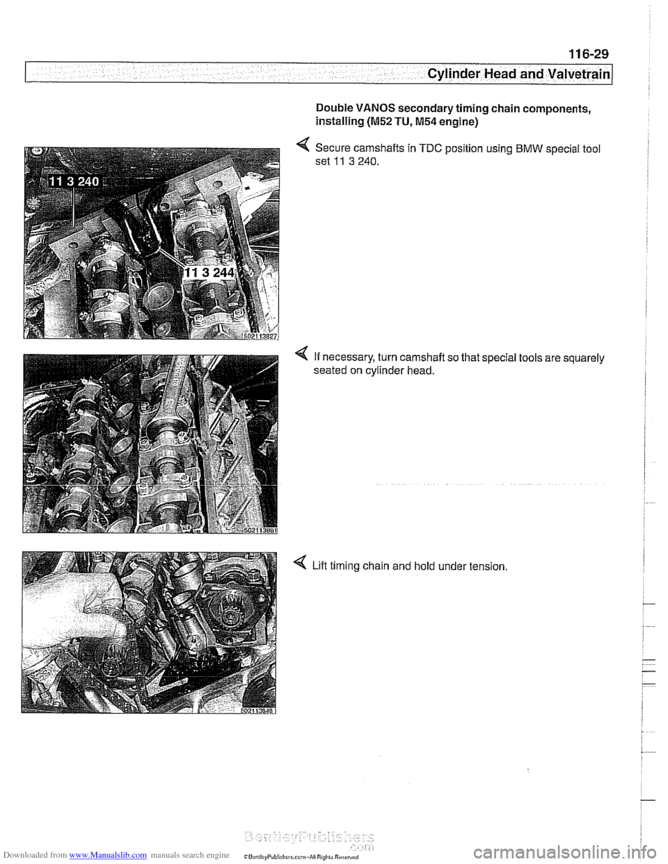
< Secure camshafts in TDC position using BMW special tool
set
11 3 240.
4 If necessary, turn camshaft so that special tools are squarely
seated on cylinder head.
4 Lift timing chain and hold under tension
Page 210 of 1002
Downloaded from www.Manualslib.com manuals search engine
/Cylinder Head and Valvetrain
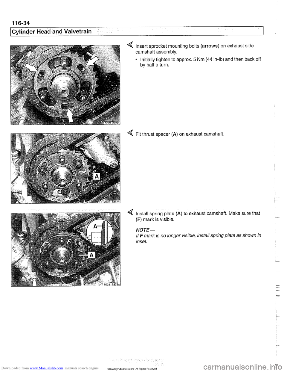
4 Insert sprocket mounting bolts (arrows) on exhaust side
carnshaft assembly.
Initially tighten to approx.
5 Nrn (44 in-lb) and then back off
by half a turn.
4 Fit thrust spacer (A) on exhaust
camshaft.
4 Install spring plate (A) to exhaust camshaft. Make sure that
(F) mark is visible.
NOTE-
If F marlc is no longer visible, install spring plate as shown in
inset.
Page 213 of 1002
![BMW 540i 1999 E39 Service Manual Downloaded from www.Manualslib.com manuals search engine
-
. - - -- Cylinder Head and valvetrain]
Turn engine over twice in direction of rotation until cylinder 1
intake and exhaust camshaft](/img/1/2822/w960_2822-212.png "BMW 540i 1999 E39 Service Manual Downloaded from www.Manualslib.com manuals search engine
-
. - - -- Cylinder Head and valvetrain]
Turn engine over twice in direction of rotation until cylinder 1
intake and exhaust camshaft")
Downloaded from www.Manualslib.com manuals search engine
-
. - - -- Cylinder Head and valvetrain]
Turn engine over twice in direction of rotation until cylinder 1
intake and exhaust camshaft lobes (arrows) face each other.
- Lock crankshaft in TDC position with BMW special tool
11 2 300.
4 Place BMW special tool set 11 3 240 over camshafts and
measure clearances.
NOTE-
@ If the exhaust side of the tool (A) is not flush with the head,
camshaft timing is incorrect. Reset camshaft timing as de-
scribed in 11
7 Camshaft Timing Chain.
Due to flexible sprocket design, VANOS unit tolerances
and play in the VANOS splines, when the camshaft timing
is set correctly, the intake side of special tool set
11 3 240
(B) may be up to 1 mm (0.04 in.) above the suiface of the
cylinder head. This is normal. Reassemble engine. Other-
wise, reset camshaft timing as describedin 1
l?Camshaft
Timing Chain.
- Remove BMW special tool 11 6 150 from front of cylinder
head.
4 Clean contact edges of cylinder head face and VANOS unit
and apply a thin coat of Three Bond
12090 or equivalent
sealing compound to surfaces.
CAUTION-
Male sure all gasket material is removed from face of cyl-
inder head. Clean sealing face and keep free of oil.
Check locating dowel
(A) and dowel sleeve (B) at top
of cylinder head for damage or incorrect installation.
- Using a new steel gasket, install VANOS unit to front of cyi-
inder head. See 117 Camshaft Timing Chain.
NOTE-
If VANOS control unit is being replaced, be sure to check and
adjust camshaft timing as described in 117 Camshaft Tim-
ing Chain.
- Reinstall engine lifting eye.
- Reconnect electrical harness connectors to camshaft posi-
tion sensors and
VANOS solenoid valves.