turn BMW 540i 1999 E39 User Guide
[x] Cancel search | Manufacturer: BMW, Model Year: 1999, Model line: 540i, Model: BMW 540i 1999 E39Pages: 1002
Page 50 of 1002
Downloaded from www.Manualslib.com manuals search engine
020-1 8
Maintenance
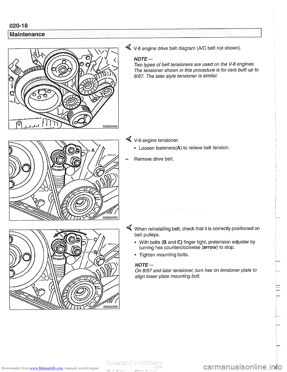
V-8 engine drive belt diagram (NC belt not shown).
NOTE-
Two types of belt tensioners are used on the V-8 engines.
The tensioner shown in this procedure is for cars built up to
8/97. The later style tensioner is similar.
4 V-8 engine tensioner.
Loosen
fasteners(A) to relieve belt tension
- Remove drive belt.
4 When reinstalling belt, check that it is correctly positioned on
belt pulleys.
With bolts
(B and C) finger tight, pretension adjuster by
turning hex counterclocltwise
(arrow) to stop.
Tighten mounting bolts.
NOTE-
On 8/97 and later tensioner, turn hex on tensioner plate to
align lowerplate mounting bolt.
Page 51 of 1002
Downloaded from www.Manualslib.com manuals search engine
Maintenance
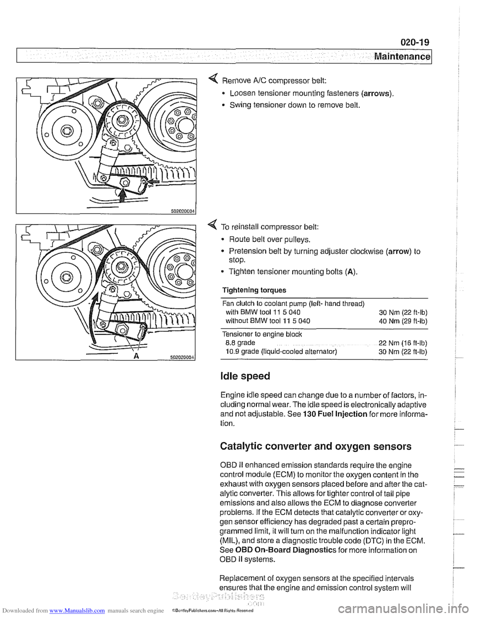
< Remove NC compressor belt:
Loosen tensioner mounting fasteners (arrows)
Swing tensioner down to remove belt.
4 To reinstall compressor belt:
Route belt over pulleys.
* Pretension belt by turning adjuster clockwise (arrow) to
stop.
- Tighten tensioner mounting bolts (A).
Tightening torques
Fan clutch to coolant pump (left- hand thread)
with BMW tool
11 5 040
30 Nm (22 ft-lb)
without BMW tool 11 5 040
40 Nm (29 ft-lb)
Tensioner to engine block
8.8 grade
22 Nm (16 ft-lb)
10.9 grade (Ilquid-cooled alternator) 30 Nm (22 ft-lb)
Idle speed
Engine idle speed can change due to a number of factors, in-
cluding normal wear. The idle speed is electronically adaptive
and not adjustable. See
130 Fuel Injection for more informa-
tion.
Catalytic converter and oxygen sensors
OBD II enhanced emission standards require the engine
control module (ECM) to monitor the oxygen content in the
exhaust with oxygen sensors placed before and after the cat-
alytic converter. This allows for tighter control of tail pipe
emissions and also allows the ECM to diagnose converter
problems. If the ECM detects that catalytic converter or oxy-
gen sensor efficiency has degraded past a certain
prepro-
grammed limit, it will turn on the malfunction indicator light
(MIL), and store a diagnostic trouble code (DTC) in the ECM.
See OBD On-Board Diagnostics for more information on
OBD
ll systems.
Replacement of oxygen sensors at the specified intervals
he engine and emission control system will
Page 81 of 1002
Downloaded from www.Manualslib.com manuals search engine
Engine Removal and lnstallationl
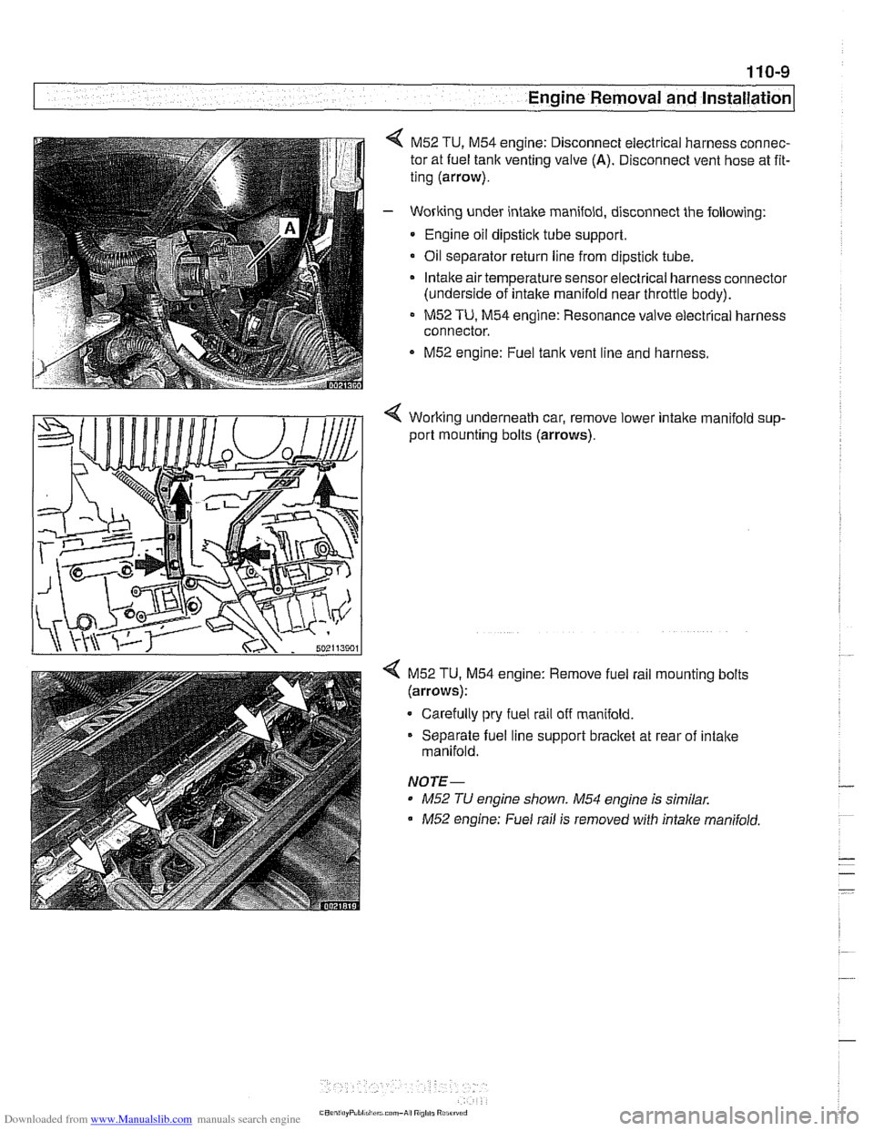
M52 TU, M54 engine: Disconnect electrical harness connec-
tor at fuel tank venting valve
(A). Disconnect vent hose at fit-
ting (arrow).
- Working under intake manifold, disconnect the following:
Engine oil dipstick tube support.
Oil separator return line from
dipsticlc tube.
Intake air temperature sensorelectrical harness connector
(underside of intake manifold near throttle body).
M52 TU, M54 engine: Resonance valve electrical harness
connector.
M52 engine: Fuel tank vent line and harness.
< Working underneath car, remove lower intalte manifold sup-
port mounting bolts (arrows).
4 M52 TU. M54 engine: Remove fuel rail mounting bolts
(arrows):
Carefully pry fuel rail off manifold.
Separate fuel line support bracket at rear of intake
manifold.
NOTE-
* M52 TU engine shown. M54 engine is similar.
M52 engine: Fuel rail is removed with intalte manifold.
Page 90 of 1002
Downloaded from www.Manualslib.com manuals search engine
I Engine Removal and Installation
WARNING -
Use extreme caution when draining and disposing of engine
coolant. Coolant is poisonous andlethal to humans andpets.
Pets are attracted to coolant because of its sweet smell and
taste. Seek medical attention immediately if coolant is ingest-
---
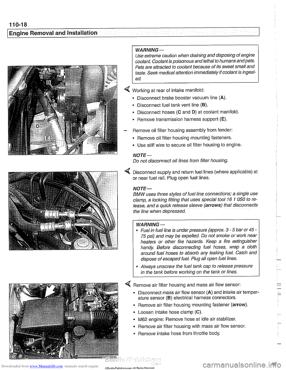
Working at rear of intake manifold:
Disconnect brake booster vacuum line (A).
Disconnect fuel tank vent line
(6).
Disconnect hoses (C and D) at coolant manifold
- Remove transmission harness support (E).
- Remove oil filter housing assembly from fender:
- Remove oil filter housing mounting fasteners.
Use stiff wire to secure oil filter housing to engine.
NOTE-
Do not disconnect oil lines from filter housing.
4 Disconnect supply and return fuel lines (where applicable) at
or near fuel rail. Plug open fuel lines.
NOTE-
BMW uses three styles of fuel line connections; a slngle use
clamp, a locking fitting that uses special tool
16 7 050 to re-
lease, and a
quiclc release sleeve (arrows) that disconnects
the line when depressed.
WARNING-
Fuel In fuel line is under pressure (approx. 3 - 5 bar or45 -
75 psi) and may be expelled. Do not smoke or worlc near
heaters or other fire hazards. Keep a fire extinguisher
handy. Before disconnecting fuel hoses, wrap a cloth
around fuel hoses to absorb any lealcing fuel. Catch and
dispose of escaped fuel. Plug all open fuel lines.
. Always unscrew the fuel tank cap to release pressure
in the tank before worlcing on the tank or lines.
< Remove air filter housing and mass air flow sensor:
Disconnect mass air flow sensor (A) and
intalte air temper-
ature sensor
(6) electrical harness connectors.
. Remove air filter housing mounting fastener (arrow).
Loosen intake hose clamp (C).
M62 engine: Remove hose at idle air stabilizer.
Remove air filter housing with mass air flow sensor.
Remove intalte hose from throttle body.
Page 92 of 1002
Downloaded from www.Manualslib.com manuals search engine
11 0-20
Engine Removal and Installation
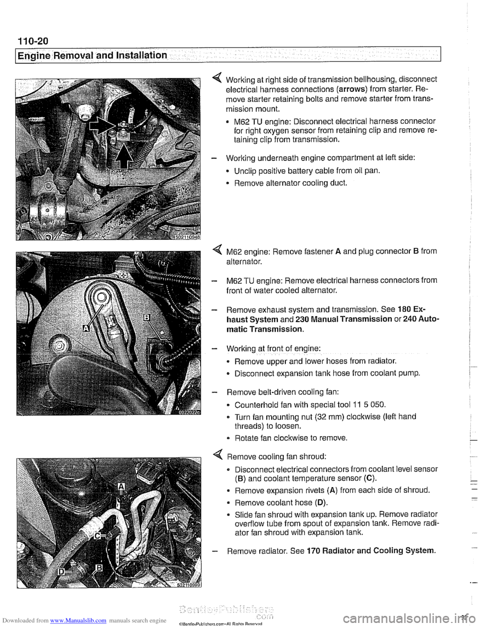
Working at right side of transmission bellhousing, disconnect
electrical harness connections (arrows) from starter. Re-
move starter retaining bolts and remove starter from trans-
mission mount.
M62 TU engine: Disconnect electrical harness connector
for right oxygen sensor from retaining clip and remove re-
taining clip from transmission.
- Working underneath engine compartment at left side:
Unclip positive battery cable from oil pan.
. Remove alternator cooling duct.
4 M62 engine: Remove fastener A and plug connector B from
alternator.
- M62 TU engine: Remove electrical harness connectors from
front of water cooled alternator.
- Remove exhaust system and transmission. See 180 Ex-
haust System and 230 Manual Transmission or 240 Auto-
matic Transmission.
- Working at front of engine:
Remove upper and lower hoses from radiator.
D~sconnect expansion tank hose from coolant pump.
- Remove belt-driven cooling fan:
Counterhold fan with special tool
11 5 050.
Turn fan mounting nut (32 mm) clockwise (left hand
threads) to loosen.
Rotate fan clockwise to remove.
Remove cooling fan shroud:
Disconnect electrical connectors from coolant level sensor
(B) and coolant temperature sensor (C).
. Remove expansion rivets (A) from each side of shroud
Remove coolant hose
(D).
Slide fan shroud with expansion tank up. Remove radiator
overflow tube from spout of expansion tank. Remove radi-
ator fan shroud with expansion tank.
Remove radiator. See
170 Radiator and Cooling System.
Page 93 of 1002
Downloaded from www.Manualslib.com manuals search engine
--
-- Engine Removal and installation' -
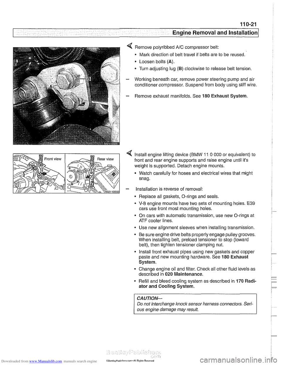
Remove polyribbed A/C compressor belt:
Mark direction of belt travel if belts are to be reused.
Loosen bolts
(A).
Turn adjusting lug (B) clocltwise to release belt tension.
Working beneath car, remove power steering pump and air
conditioner compressor. Suspend from body using stiff wire.
Remove exhaust manifolds. See
180 Exhaust System.
< lnstall engine lifting device (BMW 11 0 000 or equivalent) to
front and rear engine supports and raise engine until it's
weight is supported. Detach engine mounts.
a Watch carefully for hoses and electrical wires that might
snag.
- installation is reverse of removal:
Replace all gaskets, O-rings and seals.
V-8 engine mounts have two sets of mounting holes. E39
cars use front most mounting holes.
* On cars with automatic transmission, use new O-rings at
ATF cooler lines.
Use new alignment sleeves when installing transmission.
Be sure engine drive belts properly engage pulley grooves.
When installing belt, preload tensioner to stop (toward
belt), then tighten tensioner clamping nut.
lnstall front exhaust pipes using new gasltets and copper
paste and new mounting hardware. See
180 Exhaust
System.
Change engine oil and filter. Check all other fluid levels as
described in
020 Maintenance.
Refill and bleed cooling system as described in
170 Radi-
ator and Cooling System.
CAUTION-
Do not interchange knoclc sensor harness connectors. Seri-
ous engine damage may result
Page 99 of 1002
Downloaded from www.Manualslib.com manuals search engine
113-5
Cylinder Head Removal and Installation I
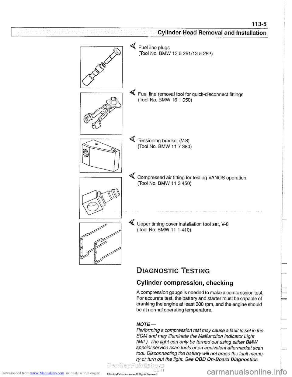
< Fuel line plugs
(Tool No.
BMW 13 5 281113 5 282)
4 Fuel line removal tool for quick-disconnect fittings
(Tool No.
BMW 16 1 050)
< Tensioning bracket (V-8)
(Tool No. BMW 11 7 380)
Compressed air fitting for testing VANOS operation
((Tool No.
BMW 11 3 450)
< Upper timing cover installation tool set, V-8
(Tool No. BMW 11 1 41 0)
Cylinder compression, checking
A compression gauge is needed to make a compression test.
For accurate test, the battery and starter must be capable of
cranking the engine at least
300 rpm, and the engine should
be at normal operating temperature.
NOTE-
Performing a compression test may cause a fault to set in the
ECM and may illuminate the Malfunction
Indicator Light
(MIL). The light can only be turned out using either
BMW
special service scan tools or an equivalent aftermarket scan
tool. Disconnecting the battery will not erase the fault memo-
ry or turn out the light. See OBD On-Board Diagnostics.
Page 102 of 1002
Downloaded from www.Manualslib.com manuals search engine
113-8
[cylinder Head Removal and Installation 1
Cylinder leak-down test
The most conclusive diagnosis of low compression symp-
toms requires a cylinder leak-down test. Using a special
tester and compressed air, each cylinder, in turn, is pressur-
ized. The rate at which the air leaks out of the cylinder, as well
as where the air leaks out, can accurately pinpoint the magni-
tude and location of the leakage.
Before attempting any repair that requires major engine dis-
assembly, use a leak-down test to confirm low compression.
~YL~NDER HEAD REMOVAL AND
~NSTALLATION (M52 ENGINE)
WARNING-
Due to rislc of personal fnjur~: be sure the engine is cold be-
fore beginning the removal procedure.
Cylinder head removal and installation is a time consuming
repair procedure requiring multiple special
service tools.
Read the entire procedure before beginning the repair.
This procedure includes the following steps:
Cylinder head, removing,
M52 engine
Cylinder head, installing,
M52 engine
Cylinder head, removing, M52 engine
- Disconnect negative (-) cable from battery in luggage com-
partment.
CAUTION-
Prior to disconnecting the battea read the battery discon-
nection cautions in 001 General Cautions and Warnings.
-
Page 105 of 1002
Downloaded from www.Manualslib.com manuals search engine
..
Cylinder Head Removal and Installation 1
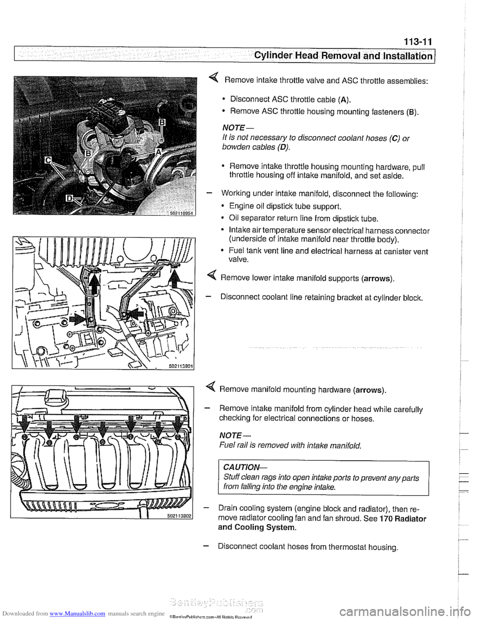
< Remove intake throttle valve and ASC throttle assemblies:
Disconnect ASC throttle cable
(A).
- Remove ASC throttle housing mounting fasteners (B).
NOTE-
It is not necessary to disconnect coolant hoses (C) 01
bowden cables (D).
Remove intake throttle housing mounting hardware, pull
throttle housing off
intake manifold, and set aside.
- Working under intake manifold, disconnect the following:
Engine oil dipstick tube support.
Oil separator return line from dipstick tube.
Intake air temperature sensor electrical harness connector
(underside of intake manifold near throttle body).
* Fuel tank vent line and electrical harness at canister vent
valve.
Remove lower intake manifold supports (arrows).
- Disconnect coolant line retaining bracket at cylinder block.
4 Remove manifold mounting hardware (arrows).
- Remove intake manifold from cylinder head while carefully
checking for electrical connections or hoses.
NOTE-
Fuel rail is removed with intake manifold,
CAUTIOI\C
Stuff clean rags into open intake ports to prevent any parts
from falling into
Nie engine intake.
- Drain cooling system (engine block and radiator), then re-
move radiator cooling fan and fan shroud. See
170 Radiator
and Cooling System.
- Disconnect coolant hoses from thermostat housing.
Page 107 of 1002
Downloaded from www.Manualslib.com manuals search engine
- - , -. I Cylinder Head Removal and lnstallatio~
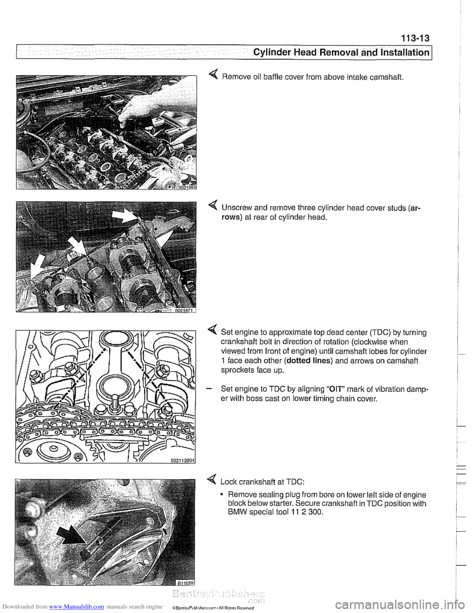
4 Remove oil baffle cover from above intake camshaft.
4 Unscrew and remove three cylinder head cover studs (ar-
rows)
at rear of cylinder head.
Set engine to approximate top dead center
(TDC) by turning
crankshaft bolt in direction of rotation (clocltwise when
viewed from front of engine) until camshaft lobes for cylinder
1 face each other (dotted lines) and arrows on camshaft
sprocltets face up.
- Set engine to TDC by aligning "OIP mark of vibration damp-
er with boss cast on lower timing chain cover.
< Lock cranltshaft at TDC:
Remove sealing plug from bore on lower left side of engine
block below starter. Secure crankshaft in
TDC position with
BMW special tool 11 2 300.