high BMW 540i 2001 E39 User Guide
[x] Cancel search | Manufacturer: BMW, Model Year: 2001, Model line: 540i, Model: BMW 540i 2001 E39Pages: 1002
Page 71 of 1002
Downloaded from www.Manualslib.com manuals search engine
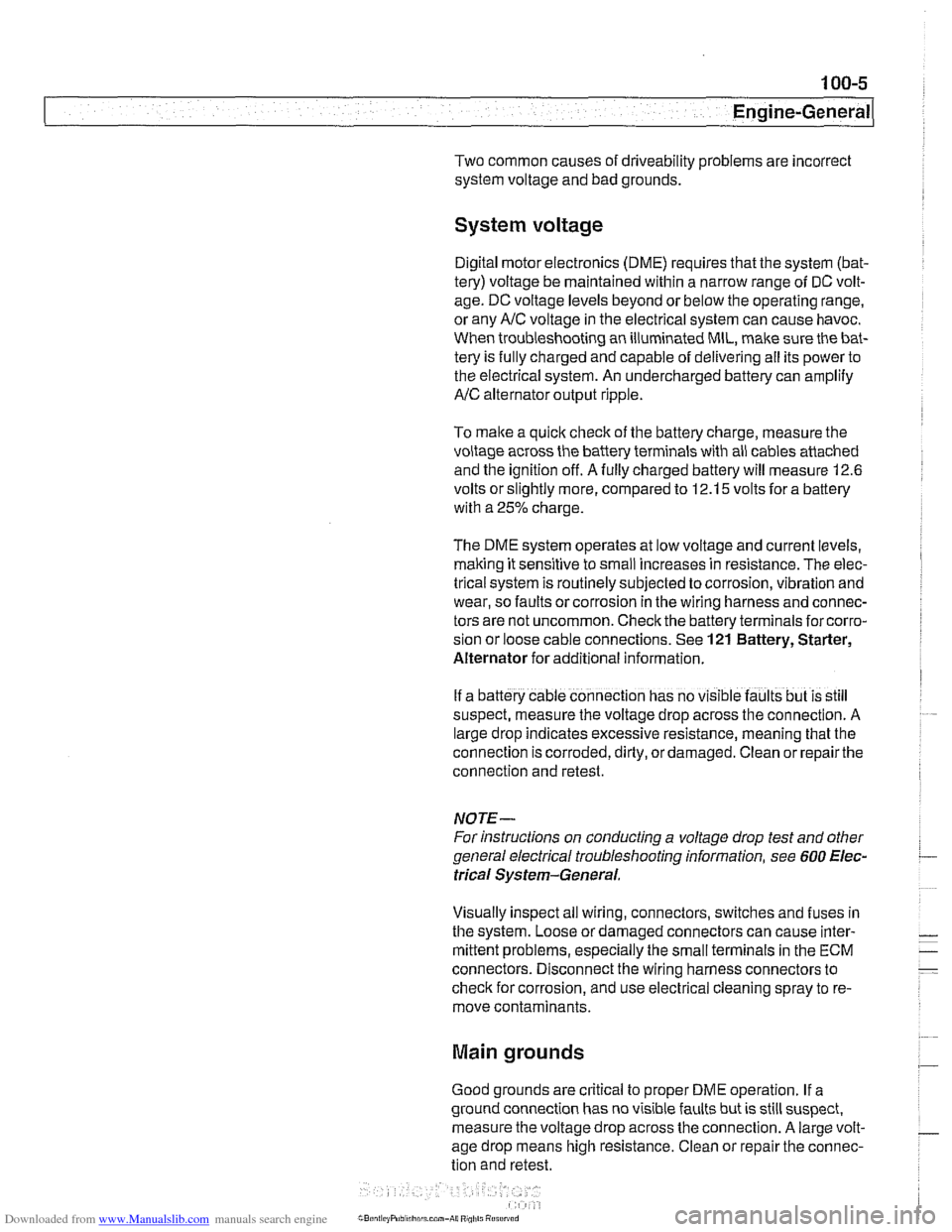
Two common causes of driveability problems are incorrect
system voltage and bad grounds.
System voltage
Digital motor electronics (DME) requires that the system (bat-
tery) voltage be maintained within a narrow range of DC volt-
age.
DC voltage levels beyond or below the operating range,
or any
AIC voltage in the electrical system can cause havoc.
When troubleshooting an illuminated MIL, make sure the bat-
tery is fully charged and capable of delivering all its power to
the electrical system. An undercharged battery can amplify
AIC alternator output ripple.
To
make a quick check of the battery charge, measure the
voltage across the battery terminals with all cables attached
and the ignition off.
Afully charged battery will measure 12.6
volts or slightly more, compared to 12.1 5 volts for a battery
with a 25% charge.
The DME system operates at low voltage and current levels,
making it sensitive to small increases in resistance. The elec-
trical system is routinely subjected to corrosion, vibration and
wear, so faults or corrosion in the wiring harness and connec-
tors are not uncommon. Check the battery terminals
forcorro-
sion or loose cable connections. See 121 Battery, Starter,
Alternator for additional information.
If a battery cable connection has no
v~sible faults but is still
suspect, measure the voltage drop across the connection. A
large drop indicates excessive resistance, meaning that the
connection is corroded, dirty, or damaged. Clean or repairthe
connection and retest.
NOTE-
For instructions on conducting a voltage drop test and other
general electrical troubleshooting information, see
600 Elec-
trical System-General.
Visually inspect all wiring, connectors, switches and fuses in
the system. Loose or damaged connectors can cause inter-
mittent problems, especially the small terminals in the ECM
connectors. Disconnect the wiring harness connectors to
check for corrosion, and use electrical cleaning spray to re-
move contaminants.
Main grounds
Good grounds are critical to proper DME operation. If a
ground connection has no visible faults but is still suspect.
measure the voltage drop across the connection. A large volt-
age drop means high resistance. Clean or repair the connec-
tion and retest.
LBuntr.yP~sbhnllcn.can#-AII A,~iltl Rcsrwsd
Page 100 of 1002
Downloaded from www.Manualslib.com manuals search engine
11 3-6
Cylinder Head Removal and Installation
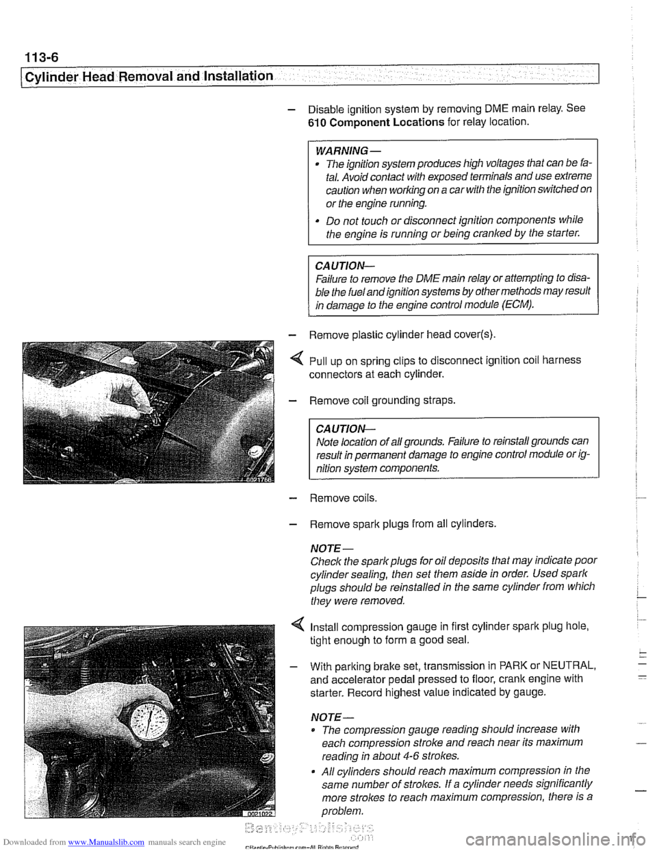
- Disable ignition system by removing DME main relay. See
610 Component Locations for relay location.
WARNING-
. The ignition system produces high voltages that can be fa-
tal. Avoid contact with exposed terminals and use
exfreme
caution when working on a car with the ignition switched on
or the engine running.
Do not touch or disconnect ignition
components while
the engine is running or being cranked by the starter.
Failure to remove the DME main relay or attempting to
disa-
bie the fuel andignition systems by other methods may result
in damaoe to the enoine control module
(ECM).
- - Remove plastic cylinder head cover(s)
,,I . ,. .*,.,,&- - Remove coil grounding straps.
I CAUTION-
I nition system components. I
- Remove coils.
- Remove spark plugs from all cylinders.
NOTE-
Check the spark plugs for oil deposits that may indicate poor
cylinder sealing, then set them aside in order. Used spark
plugs should be reinstalled in the same cylinder from which
they were removed.
4 Install compression gauge in first cylinder spark plug hole,
tight enough to form a good seal.
- With parking brake set, transmission in PARK or NEUTRAL,
and accelerator pedal pressed to floor, crank engine with
starter. Record highest value indicated by gauge.
NOTE-
* The compression gauge reading should increase with
each compression stroke and reach near its maximum
reading in about
4-6 strokes.
All cylinders should reach maximum compression in the
same number of
strolces. If a cylinder needs significantly
more strokes to reach
maximum compression, there is a
problem.
Page 101 of 1002
Downloaded from www.Manualslib.com manuals search engine
. .- . --
Lr -- - - - -- Cylinder Head Removal and Installation I -
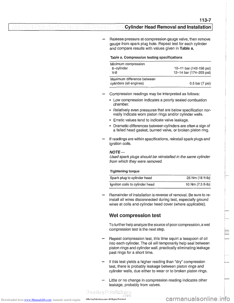
- Release pressure at compression gauge valve, then remove
gauge from spark plug hole. Repeat test for each cylinder
and compare results with values given in Table a.
Table a. Compression testing specifications
Minimum compression
6-cylinder
10-1 1 bar (142-156 psi)
V-8 12-14 bar (174-203 psi)
Maximum difference between
cylinders (all engines)
0.5 bar (7 psi)
- Compression readings may be interpreted as follows:
Low compression indicates a poorly sealed combustion
chamber.
0 Relatively even pressures that are below specification nor-
mally indicate worn piston rings
andlor cylinder walls.
Erratic values tend to indicate valve leakage.
Dramatic differences between cylinders are often a sign of
a failed head
gasket, burned valve, or broken piston ring.
- If readings are within specifications, reinstall spark plugs and
ignition coils.
NOTE-
Used spark plugs should be reinstalled in the same cylinder
from which they were removed.
Tightening torque Spark plug to cylinder head 25 Nm
(18 ft-lb)
lanition coils to cylinder head 10 Nm (7.5 ft-lb)
- Remainder of installation is reverse of removal. Be sure to re-
install all wires disconnected during test, especially ground
wires at coils and cylinder head cover (where applicable).
Wet compression test
To further help analyze the source of poorcompression,awet
compression test is the next step.
- Repeat compression test, this time squirt a teaspoon of oil
into each cylinder. The oil will temporarily help seal between
piston rings and cylinder wall, practically eliminating leakage
past rings for a short time.
- If this test yields a higher reading than "dry" compression
test, there is probably leakage between piston rings and
cylinder walls, due either to wear or to broken piston rings.
- Little or no change in compression reading indicates other
leakage, probably from valves.
Page 111 of 1002
Downloaded from www.Manualslib.com manuals search engine
Cylinder Head Removal -- and lnstallati~i
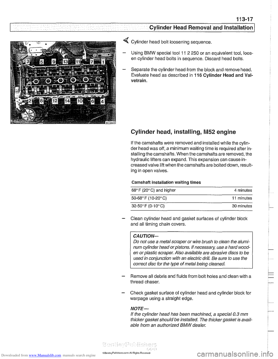
4 Cylinder head bolt loosening sequence.
- Using BMW special tool 11 2 250 or an equivalent tool, loos-
en cylinder head bolts in sequence. Discard head bolts.
- Separate the cylinder head from the block and remove head.
Evaluate head as described in
116 Cylinder Head and Val-
vetrain.
Cylinder head, installing, M52 engine
If the camshafts were removed and installed while the cylin-
der head was off, a minimum waiting time is required after in-
stalling the camshafts. When the camshafts are removed, the
hydraulic lifters can expand. This expansion can cause in-
creased valve lift when the camshafts are bolted down, result-
ing in open valves.
Camshaft installation waiting times
68" F (20" C) and higher 4 minutes
50.68' F (1 0-20" C) 11 minutes
32-50' F (0-1 0" C) 30 minutes
- Clean cylinder head and gasket surfaces of cylinder block
and all timing chain covers.
CAUTION-
Do not use a metal scraper or wire brush to clean the alumi-
num cylinder head orpistons. If necessary, use a hard wood-
en orplastic scraper. Also available are abrasive discs to be
used in conjunction with an electric drill. Be sure to use the
correct disc for the type of metal being cleaned.
- Remove all debris and fluids from bolt holes and clean with a
thread chaser.
- Check gasket surface of cylinder head and cylinder block for
warpage using a straight edge.
NOTE-
If the cylinder head has been machined, a special 0.3 mm
thicker gasket should be installed. The thicker
gasket is avail-
able from an authorized
BMW dealer.
Page 137 of 1002
Downloaded from www.Manualslib.com manuals search engine
.-
Cylinder Head Removal and Installation
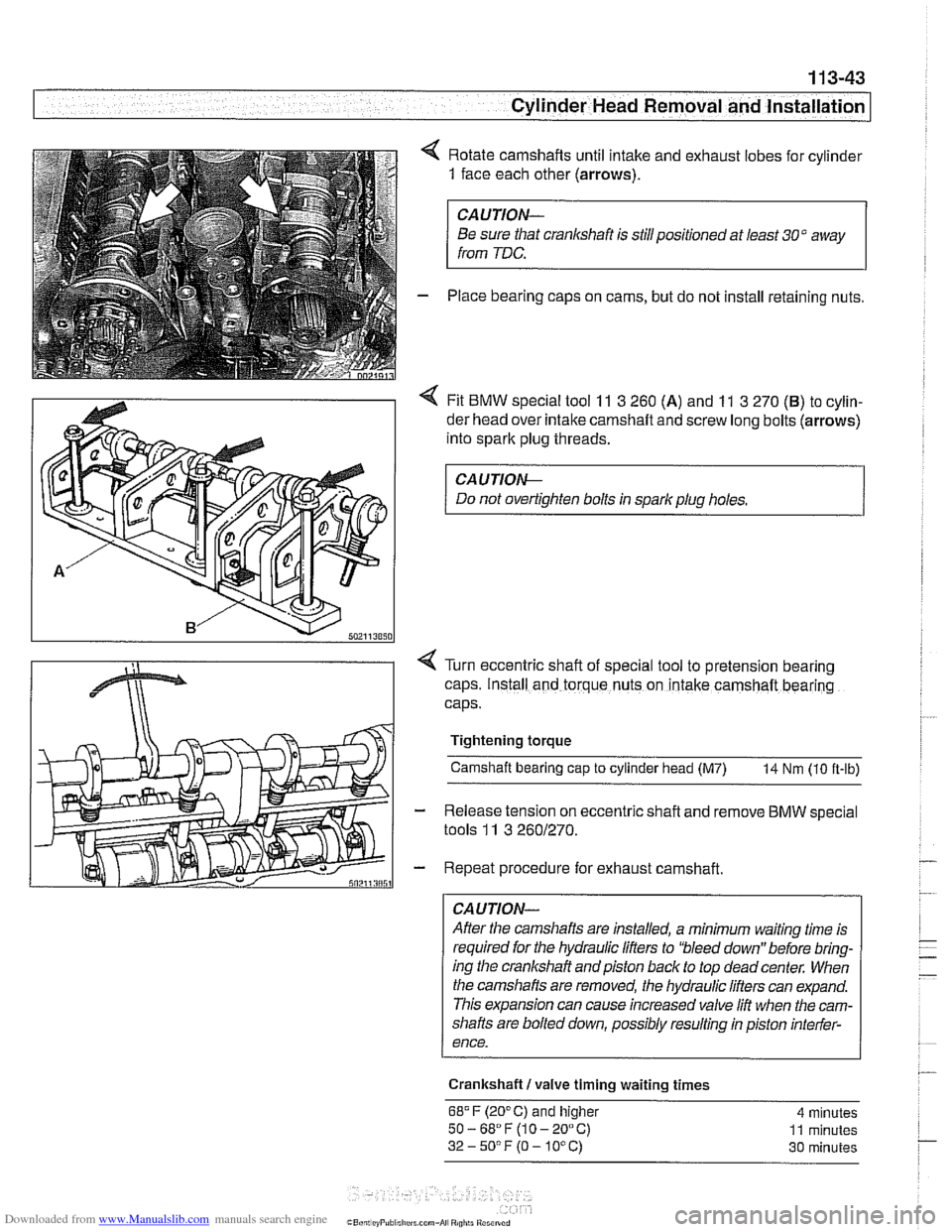
4 Rotate camshafts until intake and exhaust lobes for cylinder
1 face each other (arrows).
CAUTION-
Be sure that cranlcshaft is stillpositioned at least 30" away
from
TDC.
- Place bearing caps on cams, but do not install retaining nuts.
4 Fit BMW special tool 11 3 260 (A) and 11 3 270 (B) to cylin-
der head over intake camshaft and screw long bolts (arrows)
into spark plug threads.
CAUTIOI\C
Do not overtighten bolts in spark plug holes.
Turn eccentric shaft of special tool to pretension
bearing
caps. Install and torque nuts on intake camshaft bearing
caps.
Tightening torque Camshaft bearing
cap to cylinder head (M7) 14 Nm (10 ft-lb)
Release tension on eccentric
shaft and remove BMW special
tools
11 3 2601270.
Repeat procedure for exhaust camshaft.
CAUTION-
After the camshafts are installed, a minimum waiting time is
required for the hydraulic lifters to 'bleed down" before bring-
ing the crankshaft andpiston back to top
deadcenter. When
the camshafts are removed, the hydraulic lifters can expand.
This expansion can cause increased valve lift when the cam-
shafts are bolted down, possibly resulting in piston interfer-
ence.
Crankshaft
I valve timing waiting times
68.F (20°C) and higher 4 minutes
50-68"F(10-20°C) 11 minutes
32-5O0F(O-10°C) 30 minutes
Page 181 of 1002
Downloaded from www.Manualslib.com manuals search engine
11 6-5
I Cylinder Head and valvetrain1
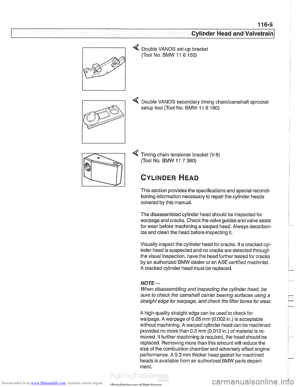
4 Timing chain tensioner bracket (V-8)
(Tool No. BMW
11 7 380)
CYLINDER HEAD
This section provides the specifications and special recondi-
tioning information necessary to repair the cylinder heads
covered by this manual.
The disassembled cylinder head should be inspected for
warpage and cracks. Check the valve guides and valve seats
for wear before machining a warped head. Always decarbon-
ize and clean the head before inspecting it.
Visually inspect the cylinder head for craclts.
If a cracked cyl-
inder head is suspected and no
craclts are detected through
the visual Inspection, have the head further tested for cracks
by an authorized BMW dealer or an ASE certified machinist.
A cracked cylinder head must be replaced.
NOJE-
When disassembling and inspecting the cylinder head, be
sure to
checlc the camshaft carrier bearing surfaces using a
straight edge for
warpage, and check the lifter bores for wear.
A high-quality straight edge can be used to
checlc for
warpage. A warpage of 0.05 mm (0.002 in.) is acceptable
without machining. A warped cylinder head can be machined
provided no more than 0.3
mm (0.012 in.) of material is re-
moved.
If further machining is required, the head should be
replaced. Removing more than this amount will reduce the
size of the combustion chamber and adversely affect engine
performance. A 0.3 mm
thicker head gasket for machined
heads is available from an authorized BMW parts depart-
ment.
Page 183 of 1002
Downloaded from www.Manualslib.com manuals search engine
Cylinder Head and valvetrain1
Hydraulic lifters, checking and replacing
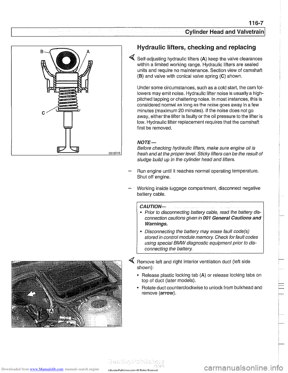
Self-adjusting hydraulic lifters (A) keep the valve clearances
within a limited working range. Hydraulic lifters are sealed
units and require no maintenance. Section view of camshaft
(6) and valve with conical valve spring (C) shown.
Under some circumstances, such as a cold start, the cam fol-
lowers may emit noise. Hydraulic lifter noise is usually a
high-
pitched tapping or chattering noise. In most instances, this is
considered normal as long as the noise goes away in a few
minutes (maximum
20 minutes). If the noise does not go
away, either the lifter is faulty or the oil pressure to the lifter is
low. Hydraulic lifter replacement requires that the camshaft
first be removed.
NOTE-
Before checking hydraulic lifters, male sure engine oil is
fresh and at the proper level.
Sticky lifters can be the result of
sludge build up in the cylinder head and lifters.
- Run engine until it reaches normal operating temperature.
Shut off engine.
- Working inside luggage compartment, disconnect negative
battery cable.
CAUTION-
Prior to disconnecting battery cable, read the baltery dls-
connection cautions given In 001 General Cautions and
Warnings.
Disconnecting the battery may erase fault
code(s)
stored in control module memory Check for fault codes
4 Remove left and right interior ventilation duct (left side
shown):
Release plastic locking tab
(A) or release loclting tabs on
top of duct (later models).
Rotate duct counterclockwise to
unloclt from bulithead and
remove (arrow).
Page 203 of 1002
Downloaded from www.Manualslib.com manuals search engine
-- - . .- -,
Cylinder Head and Valvetrain
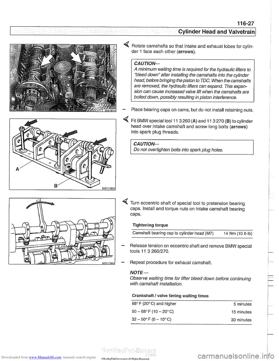
4 Rotate camshafts so that intalte and exhaust lobes for cylin-
der
1 face each other (arrows).
CAUJION-
A minimum waiting time is required for the hydraulic lifters to
'bleed down"after installing the camshafts into the cylinder
head, before bringing the piston to TDC. When the camshafts
are removed, the hydraulic lifters can expand. This expan-
sion can cause increased valve lift when the camshafts are
bolted down, possibly resulting in piston interference.
Place bearing caps on cams, but do not install retaining nuts.
4 Fit BMW special tool 11 3 260 (A) and 11 3 270 (B) to cylinder
head over
intalte camshaft and screw long bolts (arrows)
into spark plug threads.
CA UTION-
Do not overtighten bolts into spark plug holes.
< Turn eccentric shaft of special tool to pretension bearing
caps. Install and torque nuts on intake camshaft bearing
caps.
Tightening torque Camshaft bearing cap
to cylinder head (M7) 14 Nm (10 it-ib)
- Release tension on eccentric shaft and remove BMW special
tools
11 3 2601270.
- Repeat procedure for exhaust camshaft.
NOTE-
Observe waiting time for lifter bleed down before continuing
with camshaff installation.
Crankshaft
I valve timing waiting times
68°F (20°C) and higher 5 minutes
50-6S°F(10-20°C) 15 minutes
32-50DF(O-10°C) 30 minutes
Page 271 of 1002
Downloaded from www.Manualslib.com manuals search engine
Camshaft Timing Chain
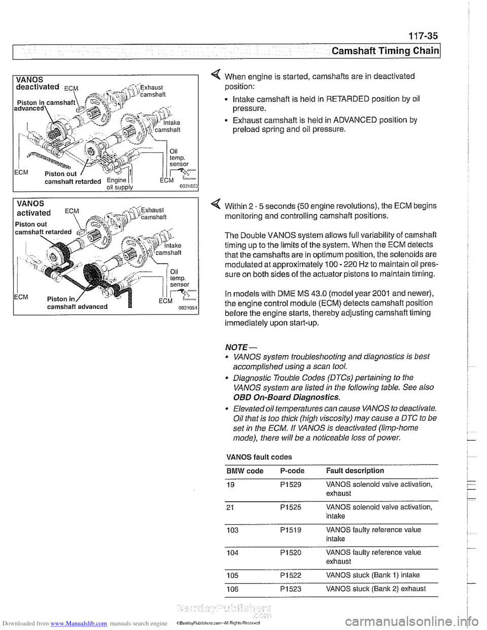
1 VANOS I 4 When engine is started, camshafts are in deactivated
camshaft
retarded Engine I i oil supply
position:
. lntalte camshaft is held in RETARDED position by oil
pressure.
Exhaust camshaft is held in ADVANCED position by
preload spring and oil pressure.
VANOS
Piston out
ECM Piston in Within 2
- 5
seconds (50 engine revolutions), the ECM begins
monitoring and controlling camshaft positions.
The Double VANOS system allows full variability of camshaft
timing up to the limits of the system. When the ECM detects
that the camshafts are in optimum position, the solenoids are
modulated at approximately 100
- 220 Hz to maintain oil pres-
sure on both sides of the actuator pistons to maintain timing.
In models with DME
MS 43.0 (model year2001 and newer),
the engine control module (ECM) detects camshaft position
before the engine starts, thereby adjusting camshaft timing
immediately upon start-up.
NOTE-
. VANOS system troubleshooting and diagnostics is best
accomplished using a scan tool.
. Diagnostic Trouble Codes (DTCs) pertaining to the
VANOS system are listed
in the following table. See also
OED On-Board Diagnostics.
Elevated oil temperatures can cause VANOS to deactivate.
Oil that is too thick (high viscosity) may cause
a DTC to be
set
in the ECM. If VANOS is deactivated (limp-home
mode), there will be a noticeable loss of power.
VANOS fault codes
BMW code P-code Fault description
19
PI529 VANOS solenoid valve activation,
exhaust
21
PI525 VANOS solenoid valve activation,
intake
103
PI519 VANOS faulty reference value
intake
104
PI520 VANOS faulty reference value
exhaust
105
PI522 VANOS stuck (Bank I) intake
106
PI523 VANOS stuck (Bank 2) exhaust
Page 332 of 1002
Downloaded from www.Manualslib.com manuals search engine
119-12
Lubrication System 1
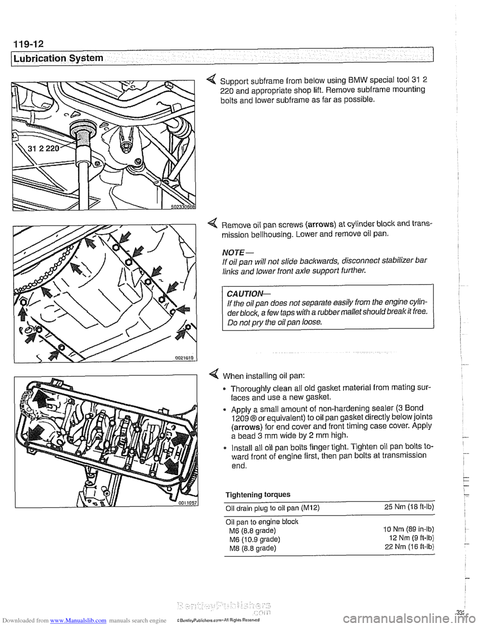
4 Support subframe from below using BMW special tool 31 2
220 and appropriate shop lift. Remove
subframe mounting
bolts and lower
subframe as far as possible.
Remove oil pan screws (arrows) at cylinder block and trans-
mission bellhousing. Lower and remove oil pan.
NOTE-
If oil pan will not slide backwards, disconnect stabilizer bar
links and lower front axle support further.
If the oil pan does not separate easily from the engine cylin-
der
block, a few taps with a rubber malletshould breakit free.
Do not
pry the oil pan loose.
When installing oil pan: Thoroughly clean all old gasket material from mating sur-
faces and use a new gasket.
Apply a small amount of non-hardening sealer
(3 Bond
12098 or equivalent) to oil pan gasket directly below joints
(arrows) for end cover and front timing case cover. Apply
a bead
3 mm wide by 2 mm high.
Install all oil pan bolts finger tight. Tighten oil pan bolts to-
ward front of engine first, then pan bolts at transmission
end.
Tightening
torques
Oil drain plug to oil pan (M12) 25 Nm (18 ft-lb)
Oil pan to engine block
MG (8.8 grade)
MG (10.9 grade)
M8 (8.8 grade)
10 Nm (89 In-lb)
12 Nm (9 ft-lb)
22 Nrn (16 R-lb)