high BMW 540i 2001 E39 Repair Manual
[x] Cancel search | Manufacturer: BMW, Model Year: 2001, Model line: 540i, Model: BMW 540i 2001 E39Pages: 1002
Page 682 of 1002
Downloaded from www.Manualslib.com manuals search engine
Steering and Wheel Alignment
Tightening torques
Tie rod
to Steering knuckle (replace self-locking nut) 65 Nm (48 it-lb)
to Steering rack 71 Nrn (52 ft-lb)
Outer tie rod end lock nut 51 Nrn (38 ft-lb)
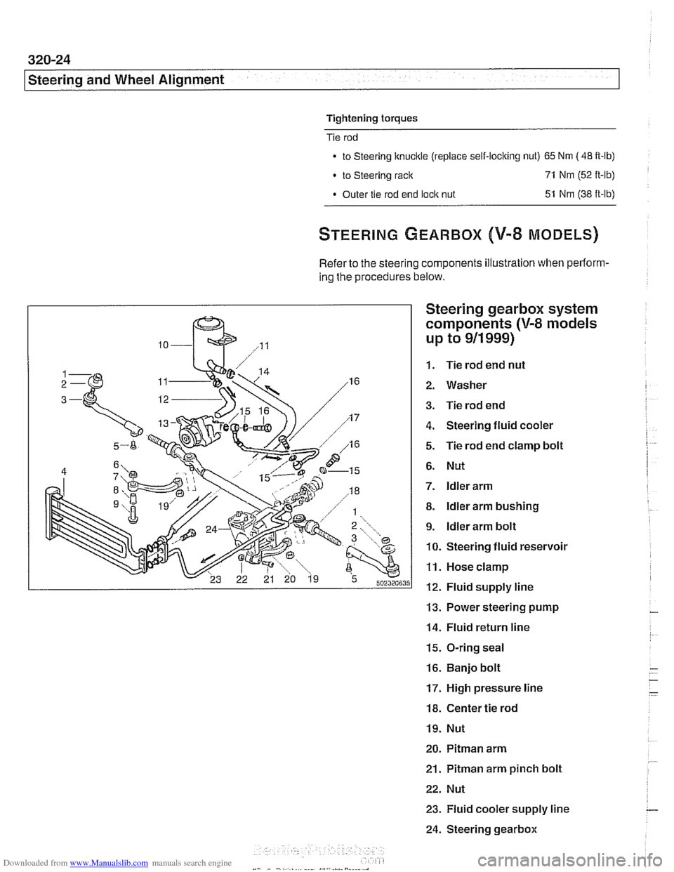
Refer to the steering components illustration when perform-
ing the procedures below.
Steering gearbox system
components
(V-8 models
up to
911 999)
1. Tie rod end nut
2. Washer
3. Tie rod end
4. Steering fluid cooler
5. Tie rod end clamp bolt
6. Nut
7. ldler arm
8. ldler arm bushing
9. ldler arm bolt
10. Steering fluid reservoir
11. Hose clamp
12. Fluid supply line
13. Power steering pump
14. Fluid return line
15. O-ring seal
16. Banjo bolt
17. High pressure line
18. Center tie rod
19. Nut
20. Pitman arm
21.
Pitman arm pinch bolt
22. Nut
23. Fluid cooler supply line
24. Steering gearbox
Page 740 of 1002
Downloaded from www.Manualslib.com manuals search engine
---
Rear Suspension
ELECTRONIC HEIGHT CONTROL
(EHC) COMPONENT REPLACEMENT
Sport Premium rear suspension is an option on Sport Wagon
models and standard on
1999 and later V-8 Sport Wagons.
This suspension incorporates electronic height control
(EHC)
using air springs.
With vehicle lifted off the ground,
if the rear air springs can be
compressed by hand, either the spring is defective or the sys-
tem is depressurized.
Locate
EHC faults using BMW scan tools DIS or MoDiC. EHC
description and some troubleshooting is covered in 300 Sus-
pension, Steering and Brakes-General.
Air spring replacement is covered earlier in this chapter. See
Air spring, removing and installing.
CAUTION-
Maintain high levels of cleanliness around air line connec-
tions when disassembling and assembling air suspension
components. Even
small dirt particles can cause leakage in
the pressurized system.
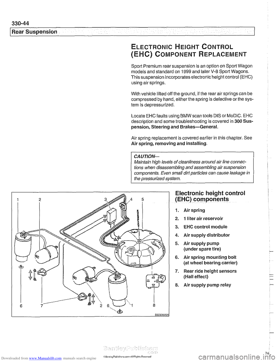
Electronic height control
(EHC) components
1. Air spring
2. 1 liter air reservoir
3. EHC control module
4. Air supply distributor
5. Airsupply pump
(under spare tire)
6. Air spring mounting bolt
(at wheel bearing carrier)
7. Rear ride height sensors
(Hall effect)
8. Air supply pump relay
Page 741 of 1002
Downloaded from www.Manualslib.com manuals search engine
-- I
I: ... . -. Rear Suspension! -- .- -
Air compressor pump relay, removing and
installing
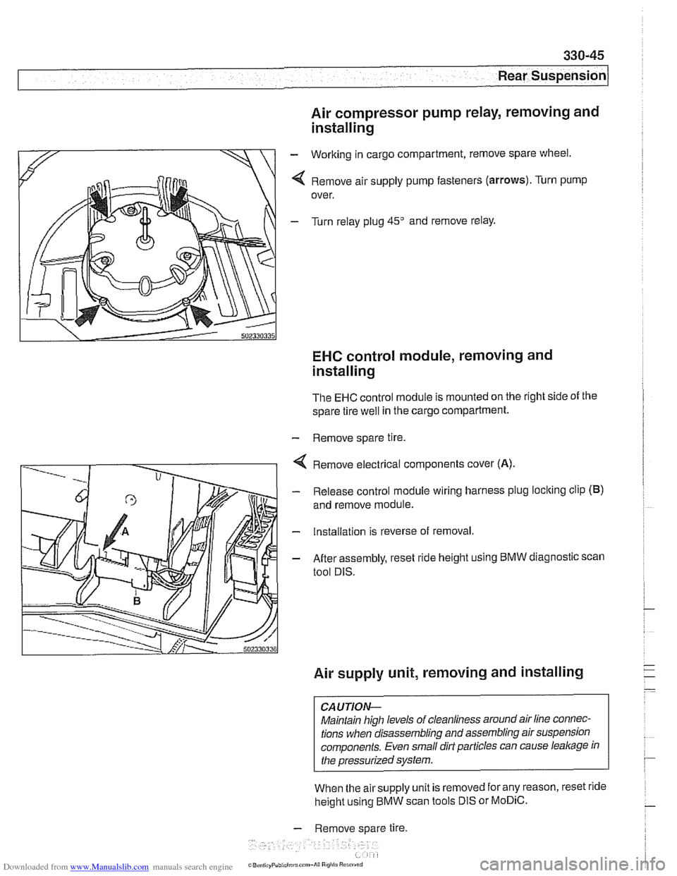
- Working in cargo compartment, remove spare wheel.
4 Remove air supply pump fasteners (arrows). Turn pump
over.
- Turn relay plug 45" and remove relay.
EHC control module, removing and
installing
The EHC control module is mounted on the right side of the
spare tire
well in the cargo compartment.
- Remove spare tire.
4 Remove electrical components cover (A).
- Release control module wiring harness plug loclting clip (B)
and remove module.
- Installation is reverse of removal.
- After assembly, reset ride height using BMW diagnostic scan
tool DIS.
Air supply unit, removing and installing
CAUTION-
Maintain high levels of cleanliness around air line connec-
tions when disassembling and assembling air suspension
components. Even small dirt particles can cause
leakage in
the pressurized system.
When the airsupply unit is removed for any reason, reset ride
height using BMW scan tools DIS or
MoDiC.
- Remove spare tire.
i~B,!n,,ayPubi.l,c~u.c~"~-A~~ R
Page 769 of 1002
Downloaded from www.Manualslib.com manuals search engine
Brakes
Warnings and cautions
WARNING-
. E39 cars require special BMWsen/ice equipment toprop-
erly bleed the brake hydraulic system. See Bleeding
Brakes for additional information.
Semi-metallic and metallic brake friction materials in
brake pads or shoes may produce dangerous dust.
Brake fluid is poisonous, corrosive and dangerous to
the environment. Wear safety glasses and rubber
gloves when worliing with
bralie fluid. Do not siphon
brake fluid with your mouth. Dispose of brake fluid
properly
Do not reuse self-locking nuts, bolts or fasteners. They
are designed to be used only once and may fail if re-
used. Always replace them with new self-locliing fas-
teners.
CAUTlOI\C
Immediately clean bralie fluid spilled on painted surfaces
and wash with water, as
bralie fluid will remove paint.
Always use new brake fluid from a fresh, unopened
container.
Brake fluid will absorb moisture from the air.
This can lead to corrosion problems in the
braking sys-
tem, and will also lower the fluid boiling point.
. Plug open lines and brake fluid ports to prevent con-
tamination.
Only tighten brake hoses on front wheels
with wheels
in straight ahead position.
If carrying out electric welding
worlc, be sure to discon-
nect electrical harness connector from electronic con-
trol module.
Do not expose electronic control modules to high sus-
tained heat, such as in a paint drying booth. Maximum
heat exposure:-95°C (203
OF) for short periods of time-
85'C (185°F) for Ions periods of time (approx. 2 hours)
Page 779 of 1002
Downloaded from www.Manualslib.com manuals search engine
Brakes
Master cylinder, removing and installing
CAUTlOI\C
Brake fluid is highly corrosive and dangerous to the environ-
ment. Dispose of it properly.
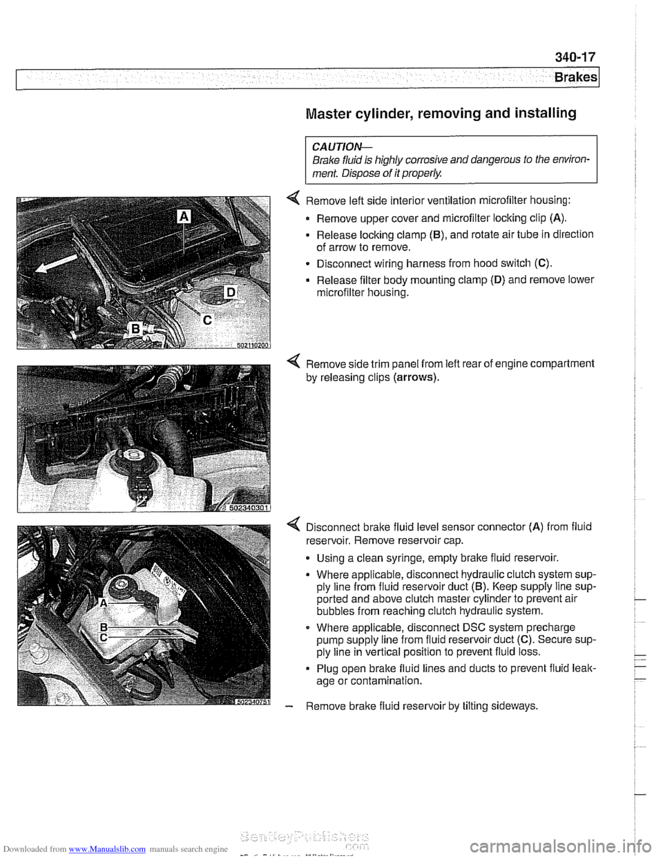
4 Remove left side interior ventilation microfilter housing:
Remove upper cover and microfilter locking clip
(A).
- Release locking clamp (B), and rotate air tube in direction
of arrow to remove.
Disconnect wiring harness from hood switch
(C).
Release filter body mounting clamp (D) and remove lower
microfilter housing.
4 Remove side trim panel from left rear of engine compartment
by releasing clips
(arrows).
4 Disconnect bralte fluid level sensor connector (A) from fluid
reservoir. Remove reservoir cap.
. Using a clean syringe, empty bralte fluid reservoir.
Where applicable, disconnect hydraulic clutch system sup-
ply line from fluid reservoir duct
(5). Keep supply line sup-
ported and above clutch master cylinder to prevent air
bubbles from reaching clutch hydraulic system.
Where applicable, disconnect DSC system precharge
pump supply line from fluid reservoir duct
(C). Secure sup-
ply line in vertical position to prevent fluid loss.
Plug open brake fluid lines and ducts to prevent fluid leak-
age or contamination.
- Remove brake fluid reservoir by tilting sideways.
Page 791 of 1002
Downloaded from www.Manualslib.com manuals search engine
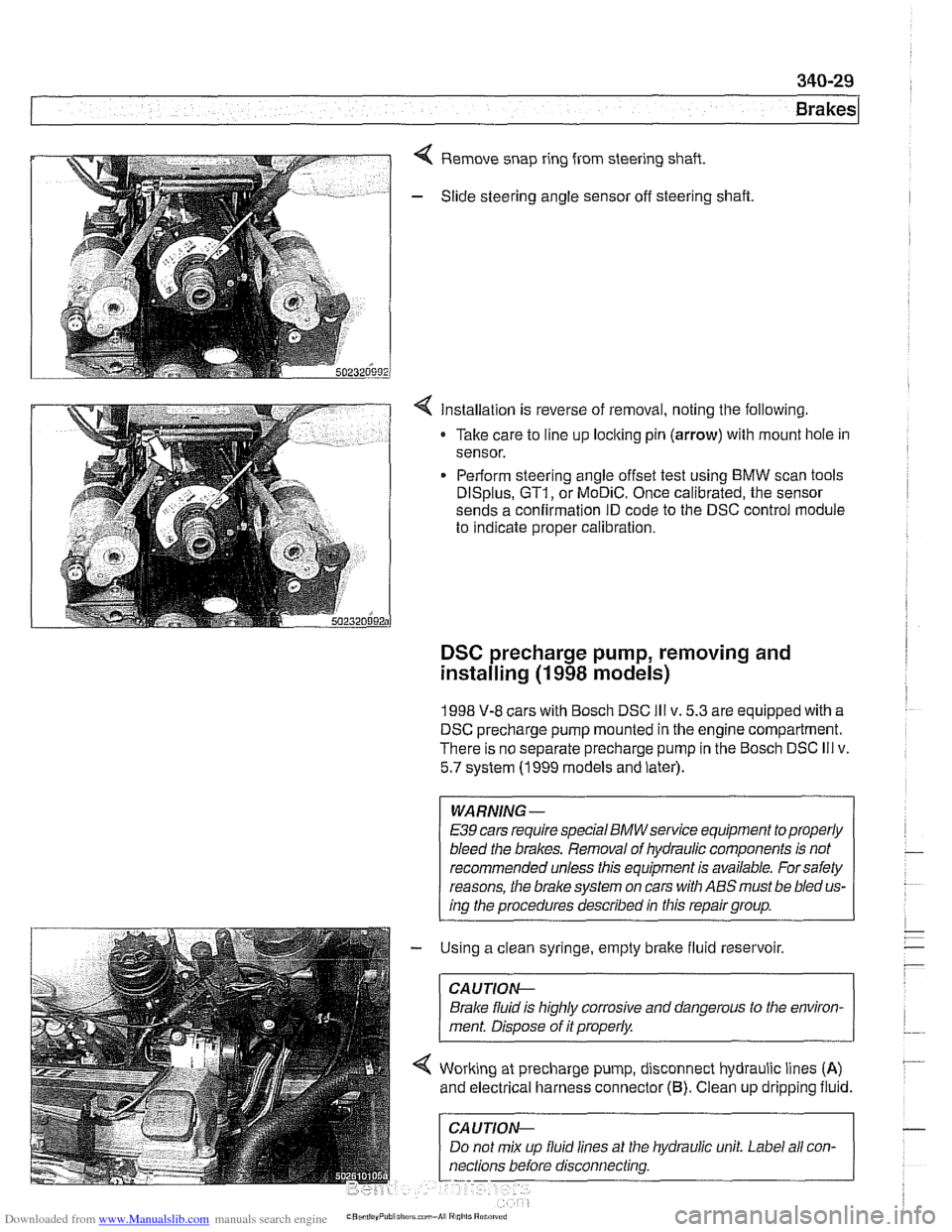
Remove snap ring from steering shaft.
- Slide steering angle sensor off steering shaft
< Installation is reverse of removal, noting the following.
Take care to line up loclting pin
(arrow) with mount hole in
sensor.
Perform steering angle offset test using BMW scan tools
DISplus, GT1, or MoDiC. Once calibrated, the sensor
sends a confirmation ID code to the DSC control module
to indicate proper calibration.
DSC precharge pump, removing and
installing
(1 998 models)
1998 V-8 cars with Bosch DSC Ill v. 5.3 are equipped with a
DSC precharge pump mounted in the engine compartment.
There is no separate precharge pump in the Bosch DSC
Ill v.
5.7 system (1999 models and later).
WARNING-
E39 cars require special BMWservice equipment to properly
bleed the brakes. Removal of hydraulic components is not
recommended unless this equipment is available. For safety
reasons, the
brake system on cars with ABS must be bled us-
ing the procedures described in this repair group.
- Using a clean syringe, empty brake fluid reservoir.
CAUTIOI\C
Brake fluid is highly corrosive and dangerous to the environ-
ment. Disoose of it
orooerlv.
Working at precharge pump, disconnect hydraulic lines (A)
and electrical harness connector (6). Clean up dripping fluid.
hydraulic unit. Label all
con-
Page 794 of 1002
Downloaded from www.Manualslib.com manuals search engine
340-32
Brakes
The procedure for removing the ABS I ASC or ABS I DSC hy-
draulic unit is similar for all models. The unit is located at the
right rear of the engine compartment.
- Using a clean syringe, empty brake fluid reservoir.
CAUTION-
Brake fluid is highly corrosive and dangerous to the environ-
ment. Dispose of it
properiw
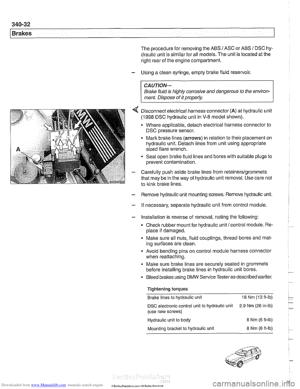
4 Disconnect electrical harness connector (A) at hydraulic unit
(1998 DSC hydraulic unit in V-8 model shown).
Where applicable, detach electrical harness connector to
DSC pressure sensor.
Mark brake lines
(arrows) in relation to their placement on
hydraulic unit. Detach lines from unit using appropriate
sized flare wrench.
Seal open brake fluid lines and bores with suitable plugs to
prevent contamination.
- Carefully push aside brake lines from retainerslgrommets
that may be in the way of hydraulic unit removal. Use care not
to
kink brake lines.
- Remove hydraulic unit mounting screws. Remove hydraulic unit.
- If necessary, separate hydraulic unit from control module.
- Installation is reverse of removal, noting the following:
Check rubber mount for hydraulic unit/control module. Re-
place if damaged.
Make sure all nuts, fluid couplings, thread bores and mat-
ing surfaces are clean.
Avoid bending pins on control module harness connector
when reattaching.
Make sure brake lines are securely seated in grommets
before installing brake lines in hydraulic unit bores.
Bleed brakes using
BMW Service Testeras described earlier.
Tightening torques Brake lines to hydraulic unit
18 Nm (13 ft-lb)
DSC electronic control unit to hydraulic unit 2.9 Nrn (26 in-lb)
(use new screws)
Hydraulic unit to body
8 Nm (6 ft-ib)
Mounting bracket to hydraulic unit 8 Nrn (6 ft-lb)
Page 797 of 1002
Downloaded from www.Manualslib.com manuals search engine
Body shell
Exterior and aerodynamics
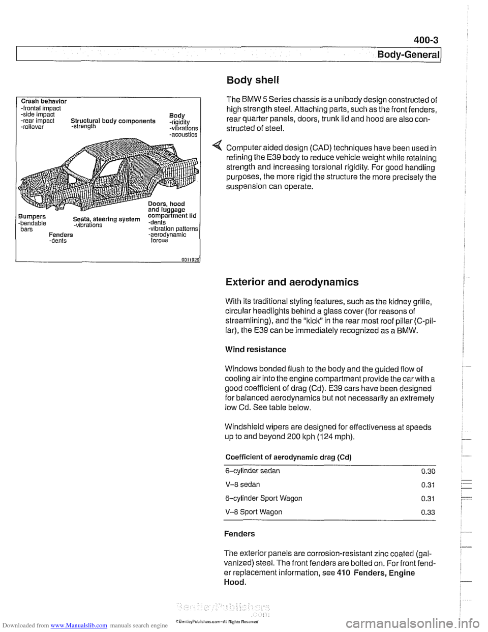
Crash behavlor -frontal impact
-side impact
Body
-rear impact Structural body components -rigidity
-rollover -strength -vibrations -acoustics
Bumpers compartment lid -bendable Seets,.steerlng system .dents -vibrations bars -vibration patterns
Fenders -aerodvnamic
With its traditional styling features, such as the ltidney grille.
circular headlights behind a glass cover (for reasons of
streamlining), and the
"kiclt" in the rear most roof pillar (C-pil-
lar), the E39 can be immediately recognized as a BMW.
The BMW 5 Series chassis is a unibody design constructed of
high strength steel. Attaching parts, such as the front fenders,
rear quarter panels, doors,
trunk lid and hood are also con-
structed of
steel.
Computer aided design (CAD) techniques have been used in
refining the
E39 body to reduce vehicle weight while retaining
strength and increasing torsional rigidity. For good handling
purposes, the more rigid the structure the more precisely the
suspension can operate.
Wind resistance
Windows bonded flush to the body and the guided flow of
cooling air into the engine compartment provide the
carwith a
good coefficient of drag (Cd).
E39 cars have been designed
for balanced aerodynamics but not necessarily an extremely
low Cd. See table below.
Windshield wipers are designed for effectiveness at speeds
up to and beyond 200
ltph (124 mph).
Coefficient of aerodynamic drag (Cd)
6-cylinder sedan 0.30
V-8 sedan 0.31
6-cylinder Sport Wagon 0.31
V-8 Sport Wagon 0.33
Fenders
The exterior panels are corrosion-resistant zinc coated (gal-
vanized) steel. The front fenders are bolted on. For front fend-
er replacement information, see
410 Fenders, Engine
Hood.
Page 798 of 1002
Downloaded from www.Manualslib.com manuals search engine
400-4
I Bodv-General
Bumpers
The front and rear bumpers are clad in high quality
deform-
able plastic and, at solid barrier impact speeds of 4 kph (2.5
mph), provide protection with virtually no damage to the
bumper
orthe vehicle. In addition to hydraulic dampeners.
which absorb the initial impact energy, these bumpers are
backed by compressible tubes. These deform in a controlled
manner at impact speeds greaterthan that
forwhich bumpers
and hydraulic dampeners are designed. This helps avoid ex-
pensive damage to the body at impact speeds up to 14 kph (9
mph).
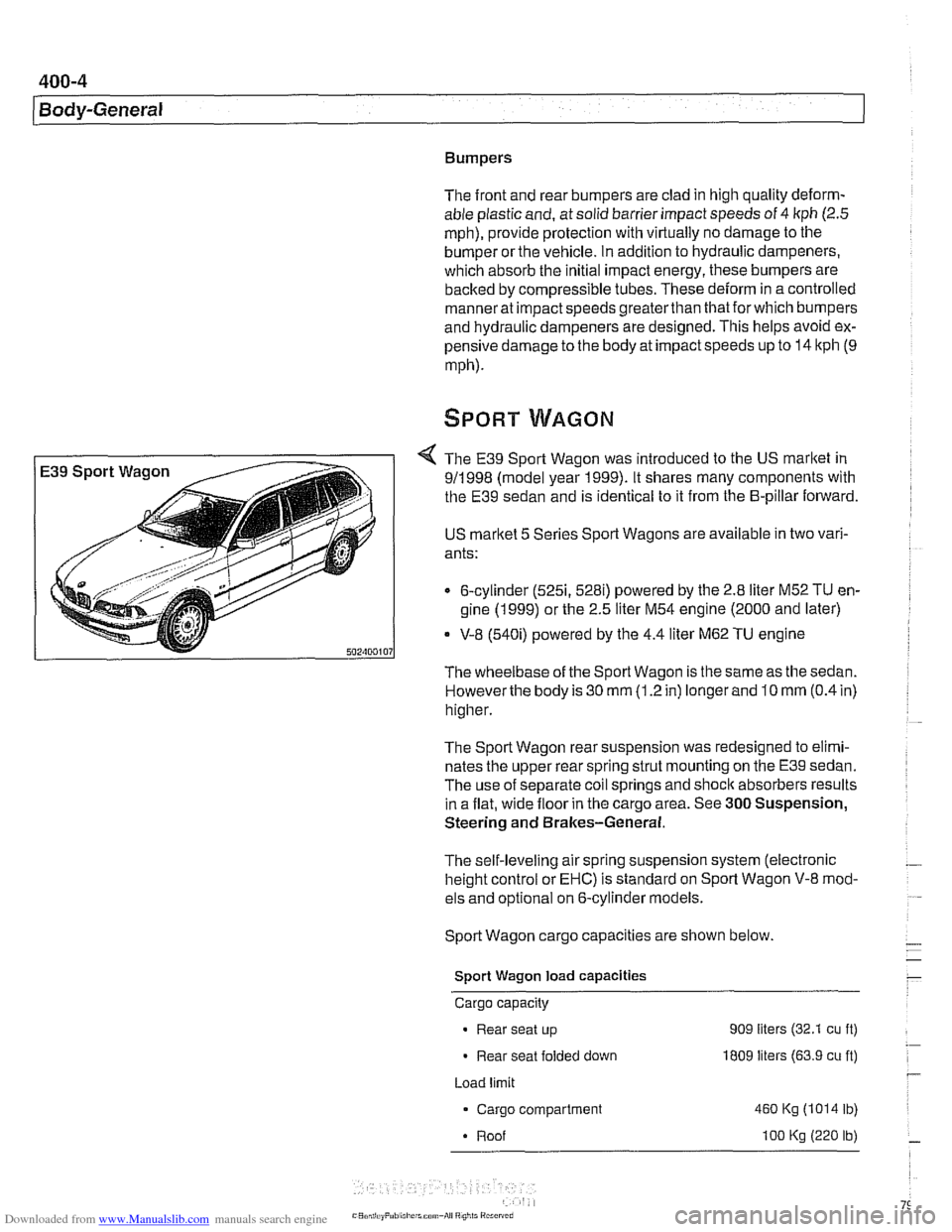
The E39 Sport Wagon was introduced to the US market in
911 998 (model year 1999). It shares many components with
the E39 sedan and is identical to it from the B-pillar forward.
US
marltet 5 Series Sport Wagons are available in two vari-
ants:
6-cylinder
(5251, 528i) powered by the 2.8 liter M52 TU en-
gine (1 999) or the 2.5 liter M54 engine (2000 and later)
* V-8 (540i) powered by the 4.4 liter M62 TU engine
The wheelbase of the Sport Wagon is the same as the sedan.
Howeverthe body is 30
mm (1.2 in) longer and 10 mm (0.4 in)
higher.
The Sport Wagon rear suspension was redesigned to elimi-
nates the upper rear spring strut mounting on the E39 sedan.
The use of separate coil springs and
shoclc absorbers results
in a flat, wide floor in the cargo area. See
300 Suspension,
Steering and Brakes-General.
The self-leveling air spring suspension system (electronic
height control or EHC) is standard on Sport Wagon V-8 mod-
els and optional on 6-cylinder models.
Sport Wagon cargo capacities are shown below.
Sport Wagon load capacities
Cargo capacity
Rear seat up 909 liters (32.1 cu ft)
Rear seat folded down I809 liters (63.9 cu ft)
Load limit
Cargo compartment
460 Kg (1014 lb)
Roof
I00 Kg (220 lb)
Page 821 of 1002
Downloaded from www.Manualslib.com manuals search engine
411-3
Doors
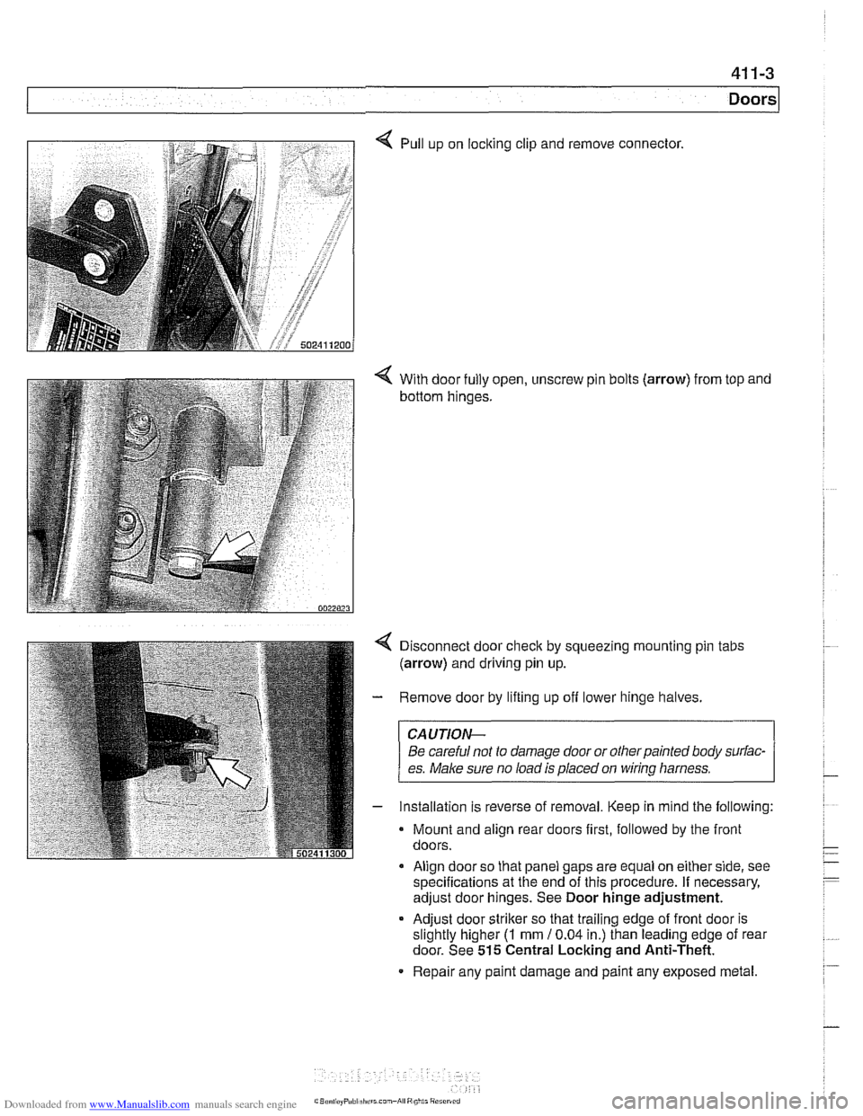
4 Pull up on locking clip and remove connector.
4 With door fully open, unscrew pin bolts (arrow) from top and
bottom hinges.
Disconnect door
check by squeezing mounting pin tabs
(arrow) and driving pin up.
Remove door by lifting up off lower hinge halves.
CAUJION-
Be careful not to damage door or otherpainted body surfac-
es.
Make sure no load is placed on wirinq harness.
Installation is reverse of removal. Keep in mind the following:
Mount and align rear doors first, followed by the front
doors.
Align door so that panel gaps are equal on either side, see
specifications at the end of this procedure. If necessary,
adjust door hinges. See Door hinge adjustment.
* Adjust door striker so that trailing edge of front door is
slightly higher
(I mm 10.04 in.) than leading edge of rear
door. See
515 Central Locking and Anti-Theft.
Repair any paint damage and paint any exposed metal.