high BMW 540i 2001 E39 Owner's Guide
[x] Cancel search | Manufacturer: BMW, Model Year: 2001, Model line: 540i, Model: BMW 540i 2001 E39Pages: 1002
Page 373 of 1002
Downloaded from www.Manualslib.com manuals search engine
Battery, Starter, ~lternatorl
WARNING-
Always wear protective goggles and clothing when perform-
ing a load test.
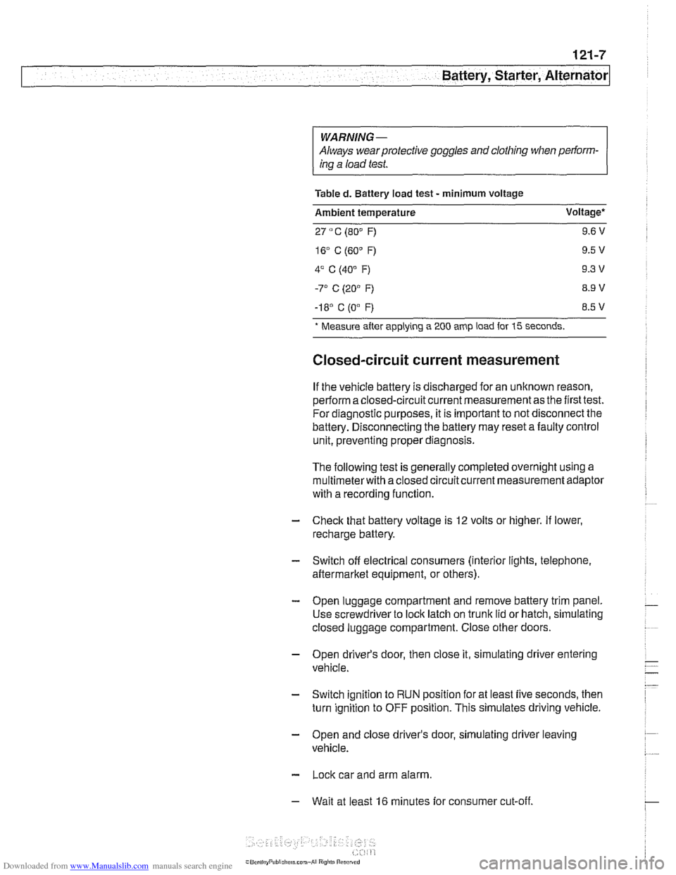
Table
d. Battery load test - minimum voltage
Ambient temperature Voltage*
27
" C (80" F) 9.6 V
-I 8' C (0"
F) 8.5 V
* Measure
after applying a 200 amp load for 15 seconds.
Closed-circuit current measurement
If the vehicle battery is discharged for an unknown reason,
perform a closed-circuit current measurement as the first test.
For diagnostic purposes, it is important to not disconnect the
battery. Disconnecting the battery may reset a faulty control
unit, preventing proper diagnosis.
The following test is generally completed overnight using a
multimeterwith a closed circuitcurrent measurement adaptor
with a recording function
- Check that battery voltage is 12 volts or higher. If lower,
recharge battery.
- Switch off electrical consumers (interior lights, telephone,
aftermarket equipment, or others).
- Open luggage compartment and remove battery trim panel.
Use screwdriver to lock latch on trunk lid or hatch, simulating
closed luggage compartment. Close other doors.
- Open driver's door, then close it, simulating driver entering
vehicle.
- Switch ignition to RUN position for at least five seconds, then
turn ignition to OFF position. This simulates driving vehicle.
- Open and close driver's door, simulating driver leaving
vehicle.
- Lock car and arm alarm.
- Wait at least 16 minutes for consumer cut-off.
Page 379 of 1002
Downloaded from www.Manualslib.com manuals search engine
Battery, Starter, ~lternatorl
Charging system quick-check
Use a digital multimeter to measure voltage across the bat-
tery terminals with key off and then again with engine running.
Battery voltage should be about 12.6 volts with key off and be-
tween 13.5 and 14.5 volts with engine running.
NOTE-
The regulated voltage (engine running) should be between
13.2 and 14.5, depending on temperature andoperating con-
ditions.
If the voltage is higher than 14.8, the voltage regula-
tor or
mulitfunction controller is most likely faulty
Check for clean and tight battery cables. Check ground cable
running from negative
(-) battery terminal to chassis and
ground cable running from engine to chassis. Check alterna-
tor drive belt condition and tension.
Charging system, checking
CAUTIOI\C
* Do not disconnect the battery while the engine is running.
Damage to the alternator and/or engine electronic systems
may result.
Only use a digital multimeter when testing charging
system components.
--7
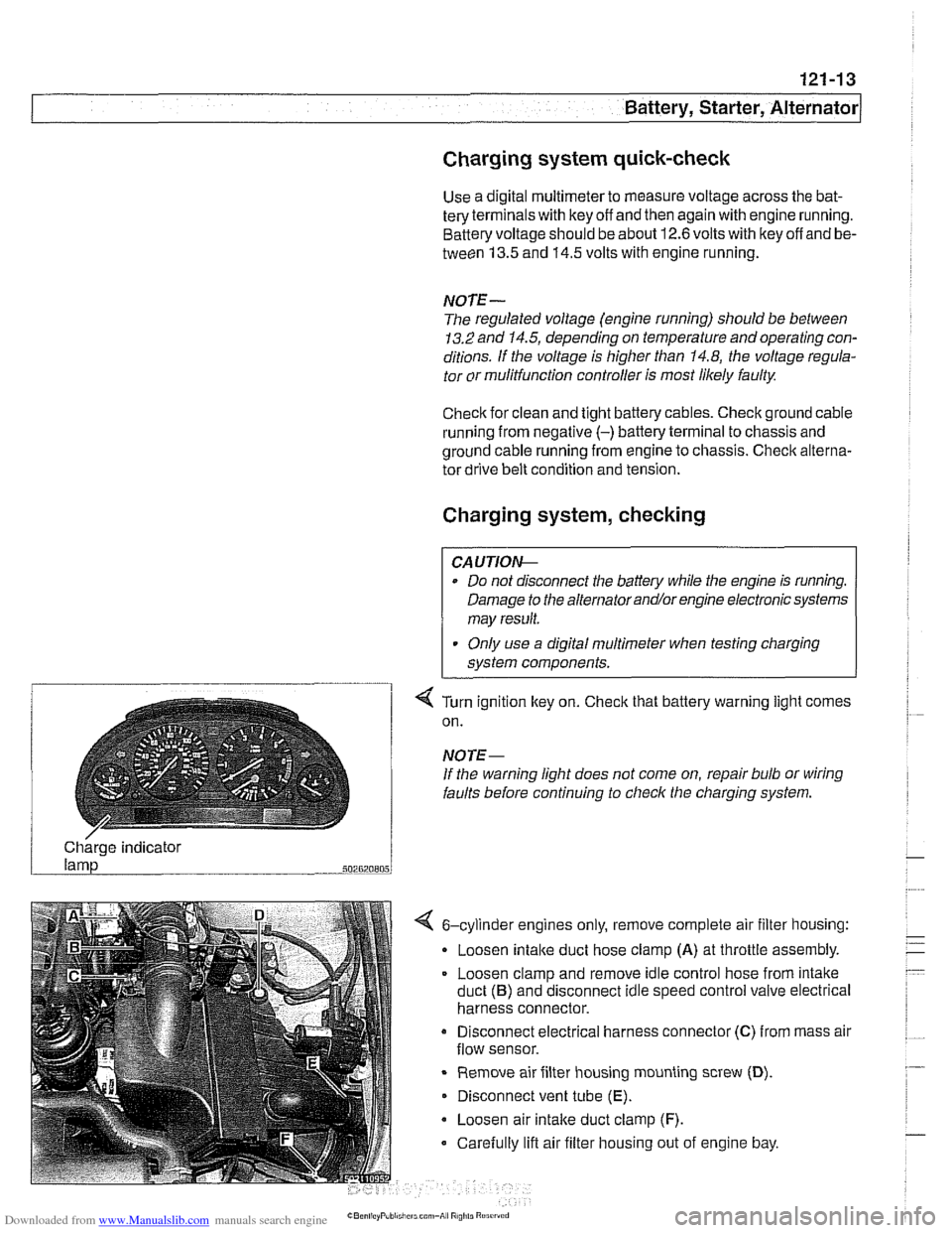
4 Turn ignition key on. Check that battery warning light comes
on.
NOTE-
If the warning light does not come on, repair bulb or wiring
faults before continuing to checlc the charging system.
/ Charge indicator
502820805
4 6-cylinder engines only, remove complete air filter housing:
Loosen
intake duct hose clamp (A) at throttle assembly.
Loosen clamp and remove idle control hose from intake
duct
(B) and disconnect idle speed control valve electrical
harness connector.
Disconnect electrical harness connector
(C) from mass air
flow sensor.
Remove air filter housing mounting screw
(D).
Disconnect vent tube (E).
Loosen air intake duct clamp (F).
Carefully lift air filter housing out of engine bay.
Page 380 of 1002
Downloaded from www.Manualslib.com manuals search engine
- -
/Battery, Starter, Alternator -- - -. - --I
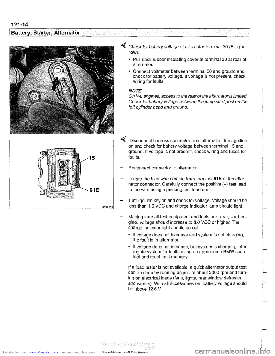
< Check for battery voltage at alternator terminal 30 (B+) (ar-
row):
Pull back rubber insulating cover at terminal 30 at rear of
alternator.
Connect voltmeter between terminal 30 and ground and
check for battery voltage.
If voltage is not present, check
wiring for faults.
NOTE-
On V-8 engines, access to the rear of the alternator is limited.
Check for battery voltage between the jump start post on the
left cylinder head and ground.
r Disconnect harness connector from alternator. Turn ianition
on and check for battery voltage between terminal
lgand
ground. If voltage is not present, check wiring and fuses for
faults.
Reconnect connector to alternator.
Locate the blue wire coming from terminal
61E of the alter-
nator connector. Carefully connect the positive
(+) test lead
to the wire using a piercing test lead end.
Turn ignition key on and check for voltage. Voltage should be
less than 1.5 VDC and charge indicator lamp should light.
- Making sure all test equipment and tools are clear, start en-
gine. Voltage should increase to
8.0 VDC or higher. The
charge indicator light should go out.
If voltage does not increase and system is not charging,
the fault is in alternator.
- If voltage does not increase, but system is charging, inter- - roaate svstem for faults usina an appropriate BMW scan - .. . tool and'reset fault memory.
- If a load tester is not available, a quick alternator output test
can be done by running engine at about 2000 rpm and turn-
- -
ing on electrical loads (fans, lights, rear window defroster, -
- and wipers). With all accessories on, battery voltage should
be above 12.6
V.
Page 395 of 1002
Downloaded from www.Manualslib.com manuals search engine
Fuel Injection
Warnings and cautions
For personal safety, as well as the protection of sensitive
electronic components, adhere to the warnings and cautions
on the following pages.
WARNING-
Gasoline is highly flammable and its vapors are explosive.
Do not smoke or work on a car near heaters or other fire
hazards when diagnosing and repairing fuel system prob-
lems. Have a fire extinguisher available in case of an emer-
gency
Renew fuel system hoses, clamps and O-rings any
time they are removed.
When working on an open fuel system, wear suitable
hand protection, as prolonged contact
with fuel can
cause illnesses and skin disorders.
* The ignition system produces high voltages that can be
fatal. Avoid contact with exposed terminals. Use ex-
treme caution when
working on a car with the ignition
switched on or the engine running.
CAUTION-
- Disconnecting the battery may erase fault code($ storedin
memory Check for fault codes prior to disconnecting the
battery cables. Read the battery disconnection cautions in
001 General Warnings and Cautions.
a Connect and disconnect the DME system wiring and
1 test equipment leads only when the ignition is switched
off.
Wait at least 1 minute after turning off the ignition be-
fore removing the engine control module (ECM) con-
nector. If the connector is removed before this time,
residualpower in the system relay may damage the
control module.
Fuel system cleaners and other chemical additives oth-
er than those specifically recommended by BMW may
damage the catalytic converter, the oxygen sensor or
other fuel supply components.
* Do not connect any test equipment that delivers a 12-
volt power supply to terminal 15 (+) of the ignition coil.
The current flow may damage the ECM. In general,
connect test equipment only as specified by BMW or
the equipment maker.
Only use a digital
multirneter for electrical tests. Only
use an LED test light for
quiclc tests.
Page 396 of 1002
Downloaded from www.Manualslib.com manuals search engine
130-6
Fuel Injection
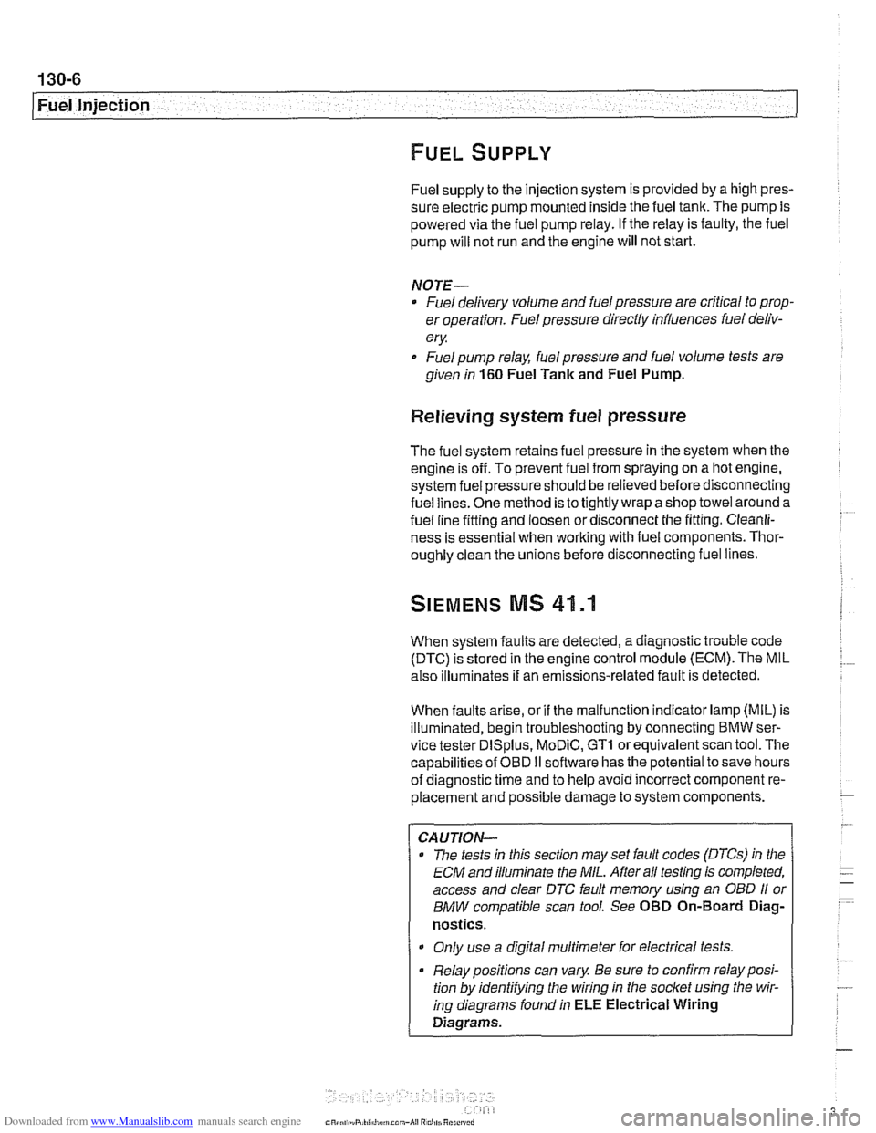
Fuel supply to the injection system is provided by a high pres-
sure electric pump mounted inside the fuel tank. The pump is
powered via the fuel pump relay. If the relay is faulty, the fuel
pump will not run and the engine will not start.
NOTE-
* Fuel delivery volume and fuel pressure are critical to prop-
er operation. Fuel pressure direcfly influences fuel deliv-
ery
Fuel pump relay, fuel pressure and fuel volume tests are
given in 160 Fuel Tank and Fuel Pump.
Relieving system fuel pressure
The fuel system retains fuel pressure in the system when the
engine is off. To prevent fuel from spraying on a hot engine,
system fuel pressure should be relieved beforedisconnecting
fuel lines. One method is to tightly wrap
ashop towel around a
fuel line fitting and loosen or disconnect the fitting. Cleanli-
ness is essential when working with fuel components. Thor-
oughly clean the unions before disconnecting fuel lines.
When system faults are detected, a diagnostic trouble code
(DTC) is stored in the engine control module (ECM). The MIL
also iiluminates if an emissions-related fault is detected
When faults arise, or if the malfunction indicator lamp (MIL) is
illuminated, begin troubleshooting by connecting BMW ser-
vice tester
DISplus. MoDiC, GTI or equivalent scan tool. The
capabilities of OBD
II software has the potential to save hours
of diagnostic time and to help avoid incorrect component re-
placement and possible damage to system components.
CAUTION-
- The tests in this section may set fault codes (DTCs) in the
ECM and illuminate the
MIL. Affer all testing is completed,
access and clear DJC fault memory using an
OED I1 or
BMW compatible scan tool. See OBD On-Board Diag-
nostics.
0 Only use a digital multimeter for electrical tests.
. Relay positions can vary Be sure to confirm relay posi-
tion by identifying the wiring in the socket using the wir-
ing diagrams found in ELE Electrical Wiring
Diagrams.
Page 412 of 1002
Downloaded from www.Manualslib.com manuals search engine
/Fuel injection
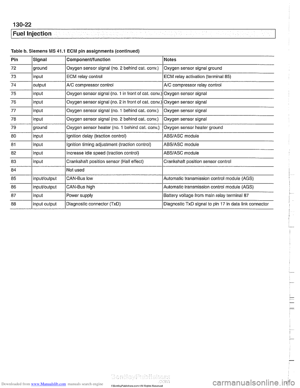
Table b. Siemens MS 41.1 ECM pin assignments (continued)
85
86
87
88 CAN-Bus low
CAN-Bus high
Power supply
Diagnostic connector
(TxD)
inputloutput
inpuWoutput
input
input output Automatic transmission control module (AGS)
Automatic transmission control module (AGS)
Battery voltage from main relay terminal 87
Diagnostic TxD signal to pin 17 in data link connector
Page 451 of 1002
Downloaded from www.Manualslib.com manuals search engine
-. -
Fuel Injection
I 68 1 / Not used
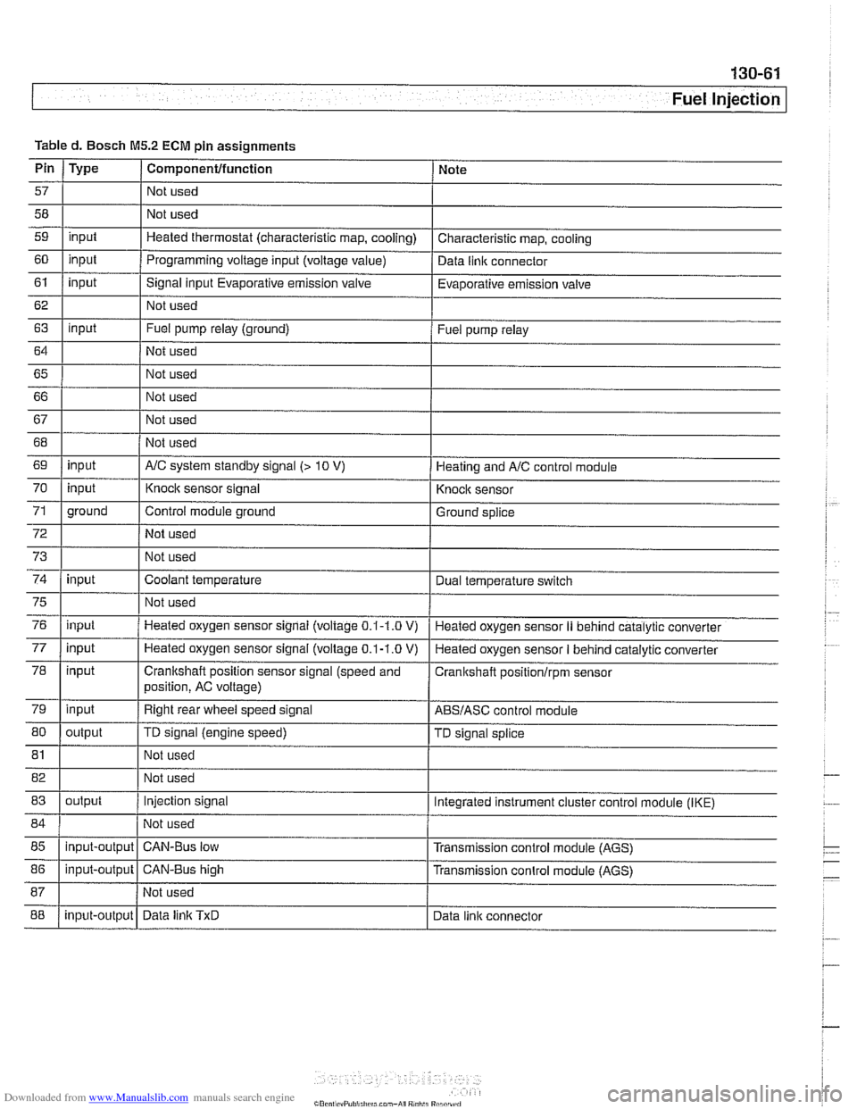
Table
d. Bosch
M5.2 ECM pin assignments
I I I
69 1 input I AIC system standby signal (> 10 V) 1 Heating and AIC control module
Pin
57
58
59
60
61
62
63
64
65 66
67
Type
input
input
input
input
I 70
72
73
74
Componentlfunction
Not used
Not used
Heated thermostat (characteristic map, cooling)
Programming voltage input (voltage
value)
Signal input Evaporative emission valve
Not used
Fuel pump relay (ground)
Not used
Not used
Not used
Not used
75
76
77
78
79
80
Note
Characteristic map, cooling
Data
llnlc connector
Evaporative emission valve
Fuel pump relay
71 1 ground I Control module ground I Ground splice
input
input
81
input input
input
input
output Not used
I
Knock sensor signal
Not used
Not used
Coolant temperature
82 1 I Not used
83
I I
Knock sensor
Dual temperature
swltch
Not used
Heated oxygen sensor signal (voltage
0.1-1.0 V)
Heated oxygen sensor
signal (voltage 0.1-1.0 V)
Crankshaft position sensor signal (speed and
position, AC voltage)
Right rear wheel speed signal
TD signal (engine speed)
85
I I I
Heated oxygen sensor II behind catalytic converter
Heated oxygen sensor
I behind catalytic converter
Cranitshaft positionlrpm sensor
ABSIASC control module
TD signal splice
84 1 / Not used 1
output
88
86
1 input-output 1 CAN-Bus high I Transmission conlrol module (AGS)
input-output
Injection signal
input-output Integrated instrument cluster control
module (IKE)
CAN-Bus low Transmission control module (AGS)
Data
linlc TxD Data link connector
Page 452 of 1002
Downloaded from www.Manualslib.com manuals search engine
130-62
Fuel Injection
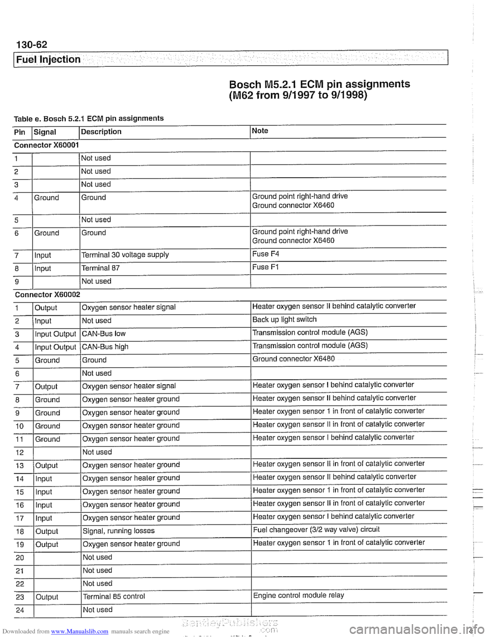
Bosch M5.2.1
ECM pin assignments
(M62 from 911 997 to 911 998)
Table e. Bosch 5.2.1 ECM pin assignments
i I I
5 1 I Not used
I
I I
Note
I I I
7 lln~ut l~erminal 30 voltage supply I Fuse
F4
Description
Pin
Ground point right-hand drive
Ground connector
X6460
I I I
Signal
Connector
X60001
Ground 4 1
2
3 Ground
Ground point right-hand drive
Ground connector
X6460 6
8
9 1
2
3
4
5
Not used
Not used
Not used
-
6
7
8
9
10 11
12
Ground
Input
Connector
X60002
Output Input Input Output
Input Output
Grniind
. -
13
14
15
Ground
- .- -
Output
Ground
Ground
Ground
Ground
16
17
18
19
20
21 22
23
.
Terminal 87
Not used
Oxygen sensor heater
slgnal
Not used
CAN-Bus low
CAN-BUS high
Ground
Output Input
ln~ut
Fuse F1
Heater oxygen sensor II behind cataiytic converter
Back up light switch
Transmission control module (AGS)
Transmission control module
(AGS)
Ground connector X6480
Not used
Oxygen sensor heater signal
Oxygen sensor heater ground
Oxygen sensor heater ground
Oxygen sensor heater ground
Oxygen sensor heater ground
Not used
Input
Input
Output
Output
Output Heater oxygen sensor
I behind catalytic converter
Heater oxygen sensor
II behind catalytic converter
Heater oxygen sensor
1 in front of catalytic converter
Heater oxygen sensor
II in front of catalytic converter
Heater oxygen sensor I behind catalytic converter
Oxygen sensor heater ground
Oxygen sensor heater ground
Oxvqen sensor heater ground Heater oxygen sensor
iI in front
of catalytic converter
Heater oxygen sensor
II behind catalytic converter
Heater oxygen sensor
1 in front of catalytic converter . -
Oxygen sensor heater ground
Oxygen sensor heater ground
Signal, running losses
Oxygen sensor iieater ground
Not used
Not used
Not used
Terminal
85 control
Heater oxygen sensor II in front of catalytic converter
Heater oxygen sensor
I behind catalytic converter
Fuel changeover
(312 way valve) circuit
Heater oxygen sensor 1 in front of catalytic converter
Engine control module relay
Page 455 of 1002
Downloaded from www.Manualslib.com manuals search engine
Fuel Injection
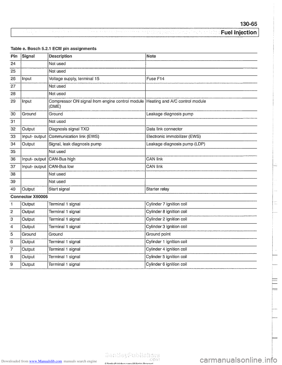
Table Pin
24
25
26
27
28
29
30
31
32
33
34
35
36
37
38
39
40
1
2
3
4
5
6
7
8
9
e. Bosch 5.2.1
Signal
Input
Input
Ground
Output Input- output
Output
Input- output
Input- output
Output
Connector
X60005
Output
Output
Output
Output
Ground
Output
Output
Output
Output
ECM pin assignments
Description
Not used
Not used
Voltage supply, terminal
15
Not used
Not used
Compressor ON signal from engine control module
(DME)
Ground
Not used
Diagnosis signal TXD
Communication
link (EWS)
Signal, leak diagnosis pump
Not used
CAN-Bus high
CAN-Bus low Not used
Not used
Start
signal
Terminal 1 signal
Terminal
1 signal
Terminal
1 signal
Terminal
1 signal
Ground
Terminal
1 signal
Terminal
1 signal
Terminal
1 signal
Terminal 1 signal Note
Fuse
F14
Heating
and AIC control module
Lealtage diagnosis pump
Data
iinit connector
Electronic immobilizer (EWS)
Leakage diagnosis pump (LDP)
CAN link
CAN link
Starter relay
Cylinder
7 ignition coil
Cylinder 8 ignition coil
Cylinder
2 ignition coil
Cylinder
3 ignition coil
Ground point
Cylinder
1 ignition coil
Cylinder
4 ignition coil
Cylinder 5 ignition coil
Cylinder
6 ignition coil
Page 466 of 1002
Downloaded from www.Manualslib.com manuals search engine
130-76
Fuel Injection
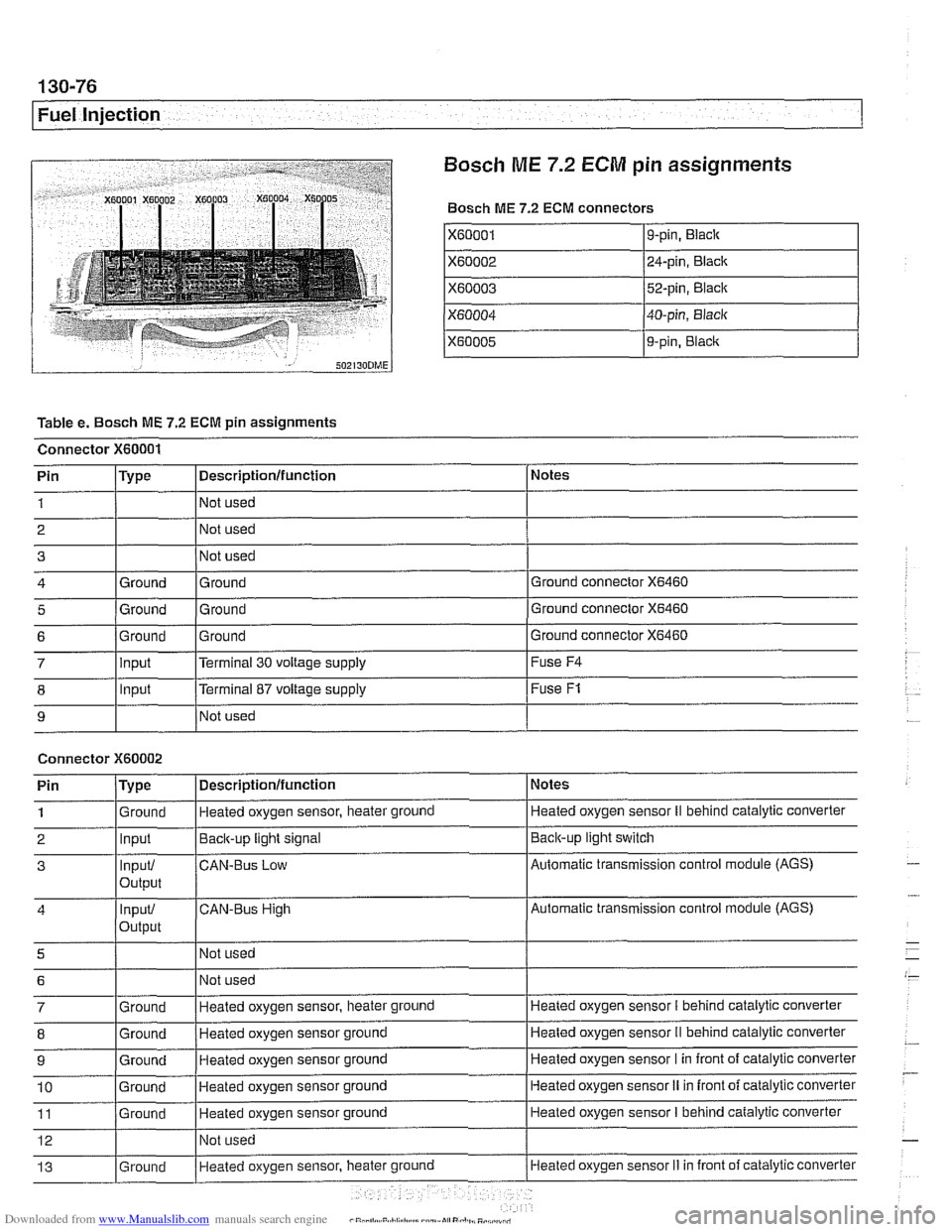
Bosch
ME 7.2 ECM pin assignments
Bosch ME 7.2 ECM connectors
X60001
X60002
X60003
X60004
X60005
Table e. Bosch ME 7.2 ECM pin assignments
Connector
X60001
I I I
8 1 lnput [Terminal 87 voltage supply I Fuse F1
9-pin, Black
24-pin, Black
52-pin, Black
40-pin, Black
9-pin,
Blaclc
I I I
9 I NO^ used I
Notes
Ground connector
X6460
Ground connector X6460
Pin 1
2 3
4
5
Connector X60002
Ground connector X6460 6
Pin
/Type I Descriptionlfunction 1 Notes
Type
Ground
Ground
7 llnput l~errninai 30 voltage supply I Fuse F4
Descriptionlfunction
Not used
Not used
Not used
Ground Ground
Ground Ground
1
2
3
4
5
6
7
8
9
10
11
12
13
. . - Ground Input
Input/
output
input/
Output
Ground
Ground
Ground
Ground
Ground
Ground Heated oxygen sensor, heater ground
Back-up
light signal
CAN-BUS Low
CAN-Bus High
Not used Not used
Heated oxygen sensor, heater ground
Heated oxygen sensor ground
Heated oxygen sensor ground
Heated oxygen sensor ground
Heated oxygen sensor ground
Not used
Heated oxvaen sensor, heater
ground
Heated oxygen sensor II behind catalylic converter
Baclcup light switch
Automatic transmission control module (AGS)
Automatic transmission control module (AGS)
Heated oxygen sensor
I behind catalytic converter
Heated oxygen sensor
II behind catalytic converter
Heated oxygen sensor I in front of catalytic converter
Heated oxygen sensor
II in front of catalytic converter
Heated oxygen sensor
I behind catalytic converter
Heated oxygen sensor
Ii in front of catalytic converter