high BMW 540i 2001 E39 Owner's Manual
[x] Cancel search | Manufacturer: BMW, Model Year: 2001, Model line: 540i, Model: BMW 540i 2001 E39Pages: 1002
Page 347 of 1002
Downloaded from www.Manualslib.com manuals search engine
11 9-27
Lubrication System
Oil pressure relief valve (V-8)
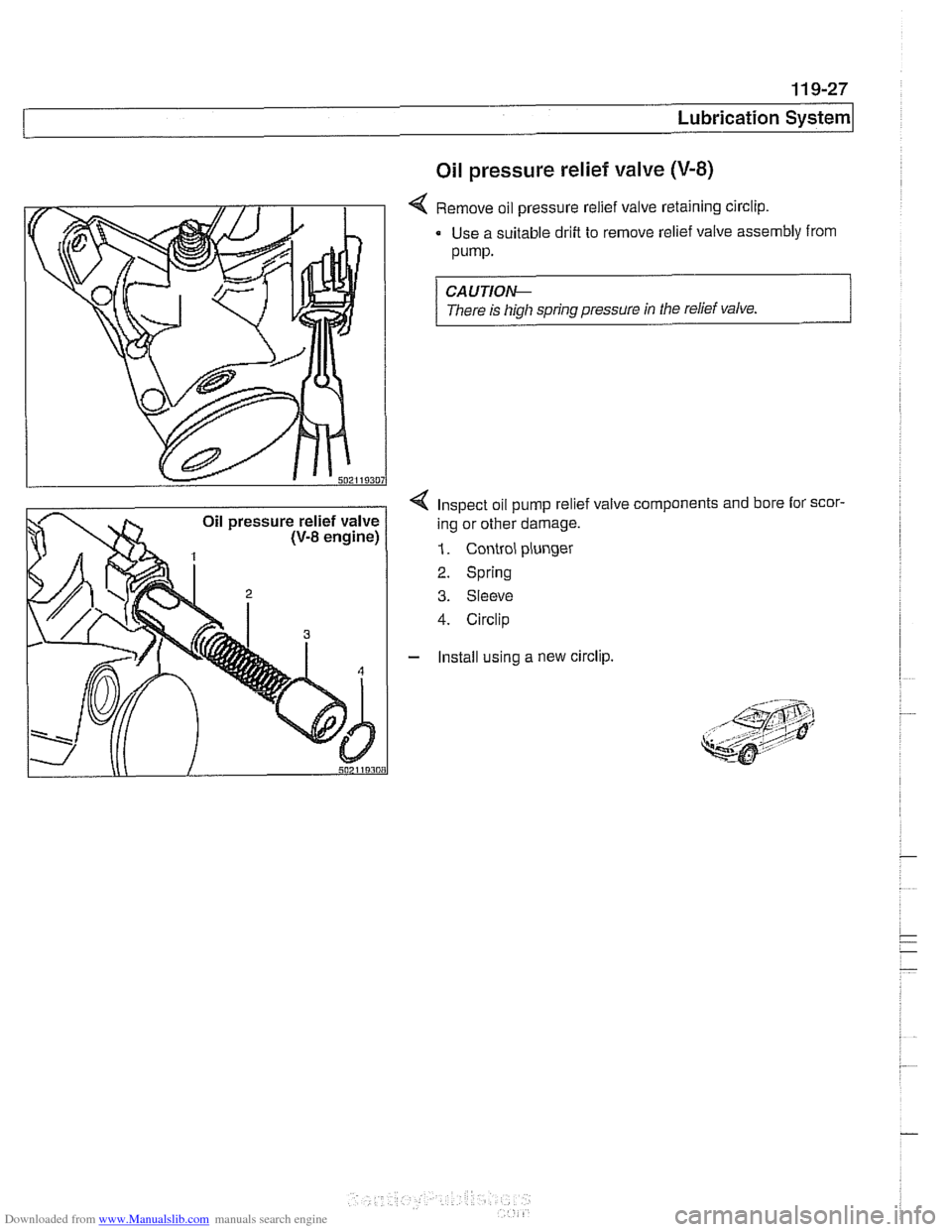
4 Remove oil pressure relief valve retaining circlip.
Use a suitable drift to remove relief valve assembly from
pump.
CAUTION--
There is high spring pressure in the relief valve.
4 Inspect oil pump relief valve components and bore lor scor-
ing or other damage.
1. Control plunger
2. Spring
3. Sleeve
4. Circlip
- Install using a new circlip.
Page 351 of 1002
Downloaded from www.Manualslib.com manuals search engine
120-3
Ignition System
Warnings and cautions
The ignition system produces dangerous high voltage. In ad-
dition the sensitive electronic components can be damaged
if
proper precautions are not adhered to.
WARNING-
* Do not touch or disconnect any cables from the coils while
the engine is running or being
cranked by the starter.
The ignition system produces high voltages that can be
fatal. Avoid contact with exposed terminals. Use ex-
treme caution when working on a car with the ignition
switched on or the engine running.
- Connect and disconnect tlie DME system wiring and
test equipment leads only when the ignition is
OFF:
Before operating the starter without starting the engine
(for example when
making a compression test) always
disable the ignition.
CA
U TIOW-
Do not attempt to disable the ignition by removing the coils
from the spark plugs.
Connect or disconnect ignition system wires, multiple
wire connectors, and ignition test equipment leads only
while the ignition is
off Switch multimeter functions or
measurement ranges only with the test probes discon-
nected.
* Do not disconnect the battery while the engine is run-
ning.
A high impedance digital multimeter should be used for
all voltage and resistance tests. An LED test light
should be used in place of an incandescent-type test
lamp.
In general, make test connections only as specified by
BMW as described in this manual, or as described by
the instrument manufacturer.
Engine management
BMW €39 engines use an advanced engine management
system known as Digital Motor Electronics (DME). DME in-
corporates on-board diagnostics, fuel injection, ignition and
other engine control functions. DME variants are listed in
Table a. Engine management systems.
Second generation On-Board Diagnostics
(OED II) is incor-
porated into the engine management systems used on the
cars covered by this manual. Use a BMW-specific electronic
scan tool, or a "Generic"
OED II scan tool to access Diagnos-
tic Trouble Codes (DTCs). DTCs can help pinpoint ignition
ine management problems.
Page 353 of 1002
Downloaded from www.Manualslib.com manuals search engine
Lnition switch
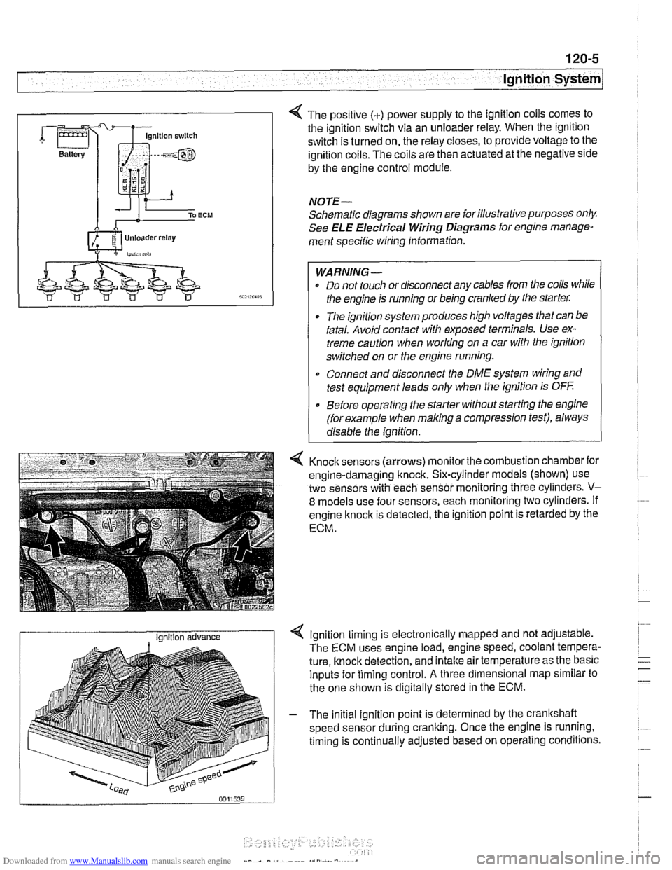
4 The positive (+) power supply to the ignition coils comes to
the ignition switch via an unloader relay. When the ignition
switch is turned on, the relay closes, to provide voltage to the
ignition coils. The coils are then actuated at the negative side
by the engine control module.
NOTE-
Schematic diagrams shown are for illustrative purposes only.
See ELE Electrical Wiring Diagrams for engine manage-
ment specific wiring information.
WARNING- Do not touch or disconnect any cables from the coils while
the engine is running or being cranked by the starter:
The ignition system produces high voltages that can be
fatal. Avoid contact with exposed terminals. Use ex-
treme caution when
working on a car with the ignition
switched on or the engine running.
* Connect and disconnect the DME system wiring and
test equipment leads only when the ignition is
OFF
Before operating the starter without starting the engine
(for example when
making a compression test), always
disable the ignition.
4 Knock sensors (arrows) monitor the combustion chamber for
engine-damaging knock. Six-cylinder models (shown) use
two sensors with each sensor monitoring three cylinders.
V-
8 models use four sensors, each monitoring two cylinders. If
engine
knock is detected, the ignition point is retarded by the
ECM.
I Ignition advance Ignition timing is electronically mapped and not adjustable.
The ECM uses engine load, engine speed, coolant tempera-
ture, knock detection, and intake air temperature as the basic
inputs for timing control.
A three dimensional map similar to
the one shown is digitally stored in the ECM.
- The initial ignition point is determined by the crankshaft
speed sensor during cranking. Once the engine is running.
timing is continually adjusted based on operating conditions.
Page 354 of 1002
Downloaded from www.Manualslib.com manuals search engine
120-6
lgnition System
lgnition system, troubleshooting
Troubleshooting ignition system faults should begin with an
interrogation of the On-Board Diagnostics (OBD
II) system.
The OBD
II system detects ignition system misfire and other
related faults. When faults are detected, the OBD
II system
stores a Diagnostic Trouble Code (DTC) in the Engine Con-
trol Module (ECM) along with other pertinent fault information.
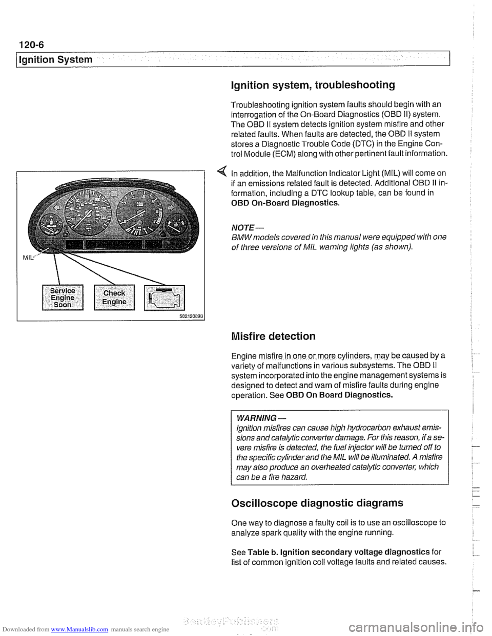
4 In addition, the Malfunction Indicator Light (MIL) will come on
if an emissions related fault is detected. Additional OBD
II in-
formation, including a DTC lookup table, can be found in
OED On-Board Diagnostics.
NOTE-
BMWmodels covered in this manual were equipped with one
of three versions of
MIL warning lights (as shown).
Misfire detection
Engine m~sfire in one or more cylinders, may be caused by a
var~ety of malfunctions in various subsystems. The OBD II
system ~ncorporated into the engine management systems is
des~gned to detect and warn of misfire faults during englne
operat~on. See OED On Board Diagnostics.
WARNING -
lgnition misfires can cause high hydrocarbon exhaust emis-
sions andcatalytic converter damage. For this reason, if a se-
vere misfire is detected, the fuel injector
will be turned off to
the specific cylinder and the
MIL will be illuminated. A misfire
may also produce an overheated catalytic converter, which
can be a fire hazard.
Oscilloscope diagnostic diagrams
One way to diagnose a faulty coil is to use an oscilloscope to
analyze spark quality with the engine running.
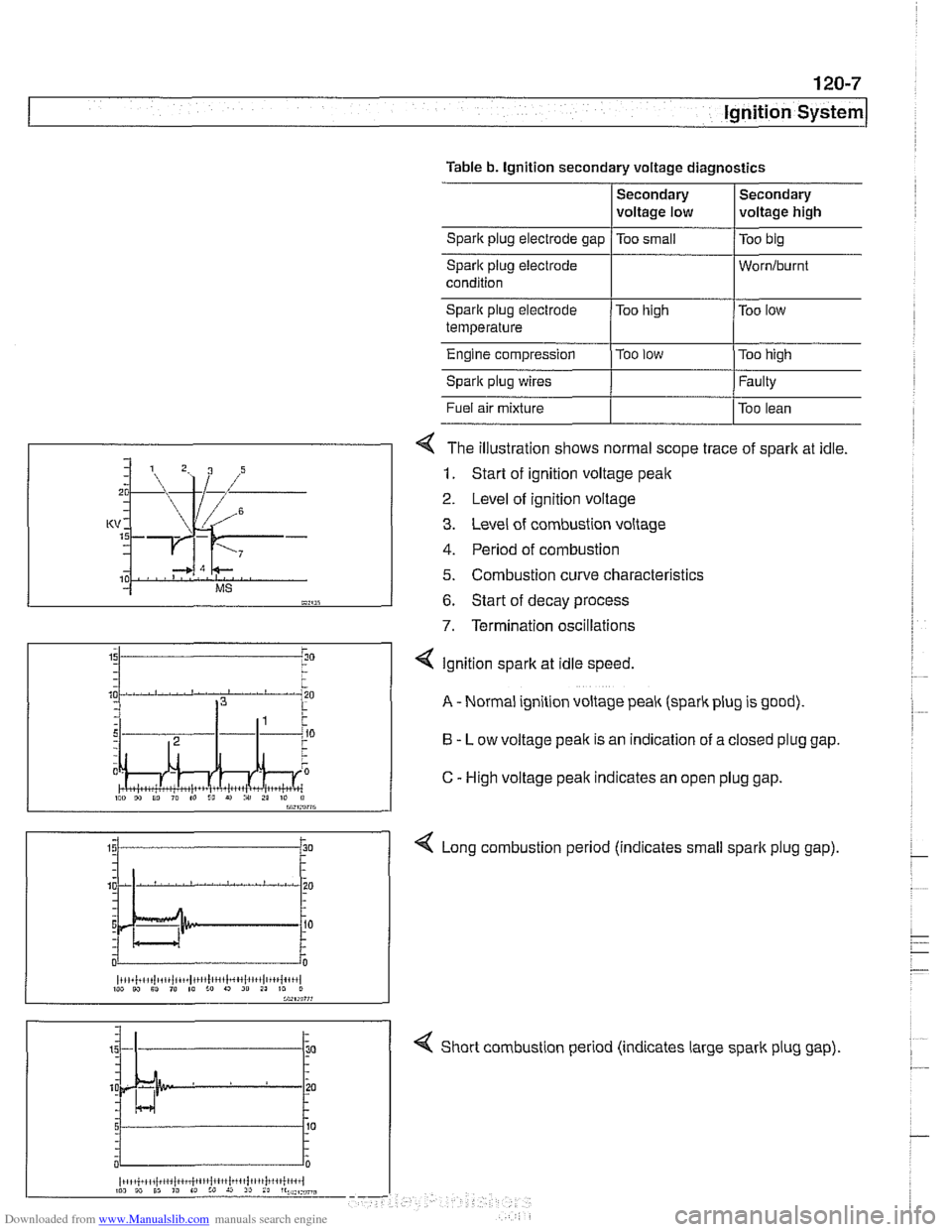
See Table b. lgnition secondary voltage diagnostics for
list of common ignition
coil voltage faults and related causes.
Page 355 of 1002
Downloaded from www.Manualslib.com manuals search engine
120-7
Ignition System
Spark plug electrode gap /Too small /TOO big
Table
b. Ignition secondary voltage diagnostics
Secondary
voltage low
Fuel air mixture
I I Too lean
Secondary
voltage high
Spark plug electrode
Worniburnt
4 The illustration shows normal scope trace of spark at idle.
1. Start of ignition voltage peak
2 Level of ignition voltage
3. Level of combustion voltage
4. Period of combustion
5. Combustion curve characteristics
6. Start of decay process
7. Termination oscillations
Spark plug electrode
temperature
Engine compression
Spark plug wires
4 Short combustion period (indicates large spark plug gap).
Too
high
Too
low
I"" 9, 10 I" to I!, r) i" 21 10 il bW,rn?7G
Too low
Too high
Faulty
4 Ignition spark at idle speed.
A - Normal ignition voltage peak (spark plug is good).
B - Low voltage peak is an indication of a closed plug gap.
C
- High voltage peak indicates an open plug gap.
< Long combustion period (indicates small spark plug gap).
~i,+i!,~,i~tiii~iit~~,t1!lc,',l~~4~l~,~,l,~+~{+',,l 1W W Sl ,@ 10 :o 9 20 21 10 0
Page 357 of 1002
Downloaded from www.Manualslib.com manuals search engine
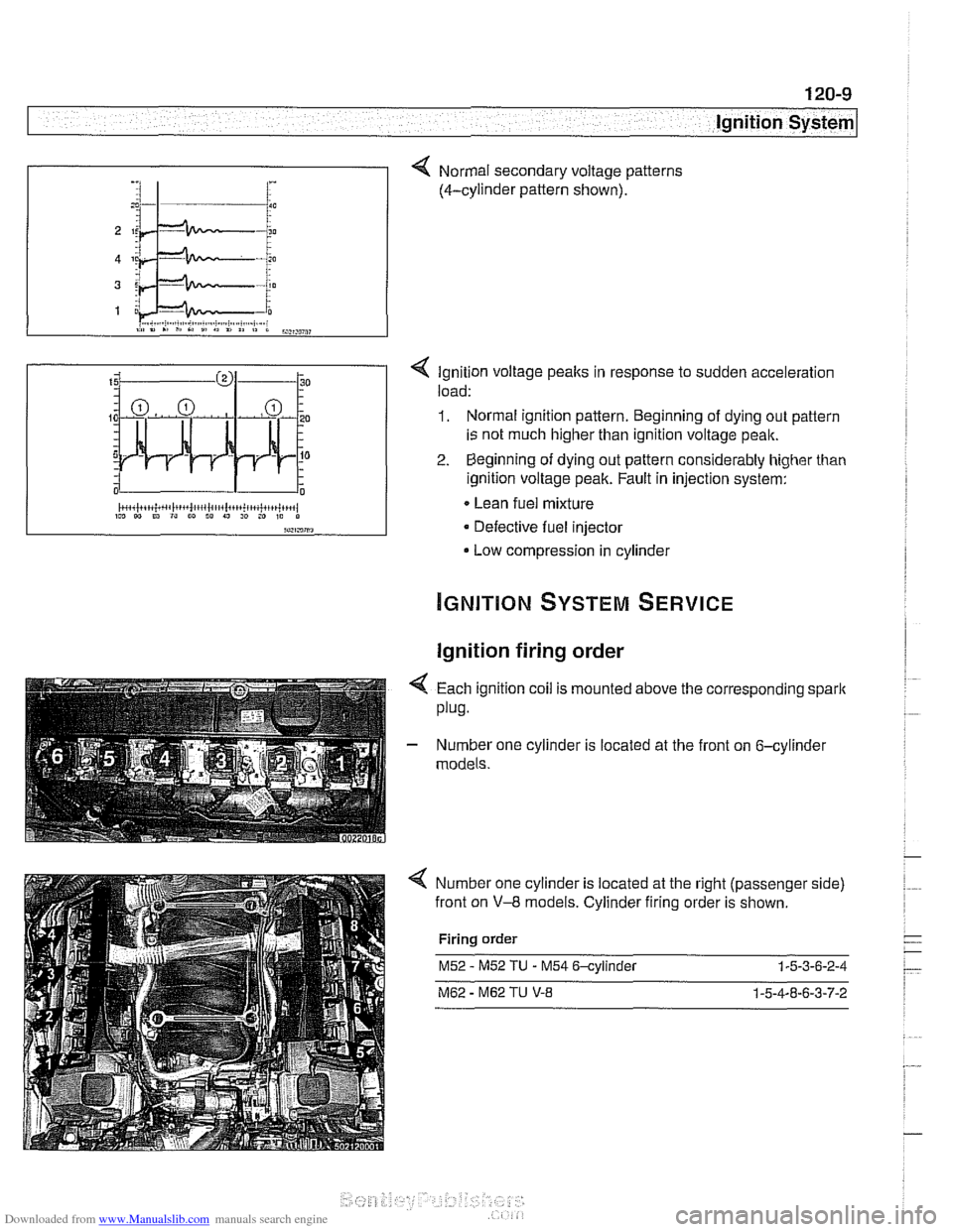
< Ignition voltage peaks in response to sudden acceleration
load:
1. Normal ignition pattern. Beginning of dying out pattern
is not much higher than ignition voltage peak.
2. Beginning of dying out pattern considerably higher than
ignition voltage peak. Fault in injection system:
Lean fuel mixture
Defective fuel injector
Low compression in cylinder
-, :I 1- i :
Ignition firing order
Normal secondary voltage patterns
(4-cylinder pattern shown).
4 Each ignition coil is mounted above the corresponding spark
plug.
- Number one cylinder is located at the front on 6-cylinder
models.
Number one cylinder is located at the right (passenger side)
front on
V-8 models. Cylinder firing order is shown.
Firing order
M52 - M52 TU - M54 6-cylinder 1-5-3-6-2-4
M62 - M62 TU V-8 1-5-4-8-6-3-7-2
Page 359 of 1002
Downloaded from www.Manualslib.com manuals search engine
Ignition System
- Turn ignition on and check for battery voltage,
If battery voltage is not present,
checlt wire between termi-
nal
15 and the unloader relay. See ELE Electrical Wiring
Diagrams.
- Turn ignition off.
Remove coil and inspect coil housing for hairline
cracks or
leaking casting material. Replace any
cracked or leaking coil.
NOTE-
A leaky coil may indicate a faulty Engine Control Module
(ECM). Check ECM before installing a new coil.
CAUTION-
Note location of coilground straps before coil removal; rein-
stall in the same location.
Use a multimeter to test:
Coil primary resistance at coil terminals.
Sparlt plug connector resistance.
* Compare results to specification in Table c. lgnition coil
resistance.
Table c. Ignition coil resistance
Coil secondary
resistance
Spark plug connector:
Bosch 1 .O I( ohm t 20%
1.8 ir ohm t 20%
Component
Co~l prlmary
resistance
- Replace ignition coil or sparlt plug connector if resistance
readings do not meet specifications.
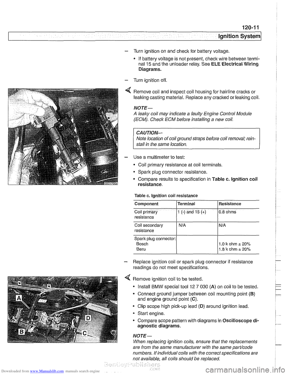
4 Remove ignition coil to be tested.
Install
BMW special tool 12 7 030 (A) on coil to be tested.
Connect ground jumper between coil mounting point
(B)
and engine ground point (C).
Clip scope high pick-up lead (D) around ignition lead.
Start engine.
Compare scope pattern with diagrams in Oscilloscope
di-
agnostic diagrams.
NOTE-
When replacing ignition coils, ensure that the replacements
Terminal
1 (-) and 15 (+)
are
from the same manufacturer with the same partlcode
numbers. If individual coils with the correct specifications are
not available. all coils should be
re~laced.
Resistance
0.8 ohms
Page 369 of 1002
Downloaded from www.Manualslib.com manuals search engine
Battery, Starter, ~lternatorl
@ TO fuse & relay panel Battery Safety Terminal
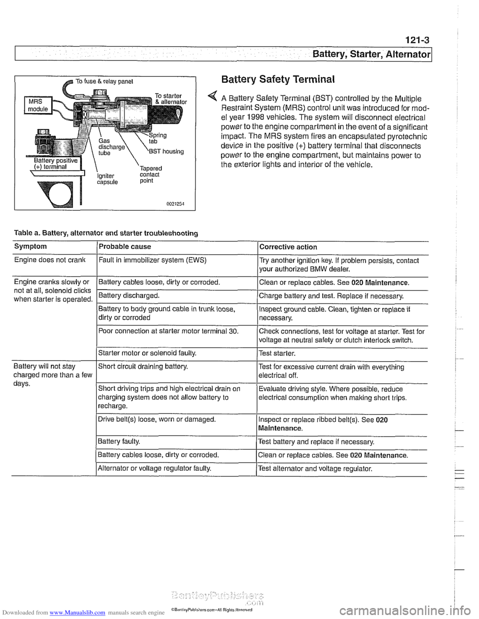
A Battery Safety Terminal (BST) controlled by the Multiple
Restraint System (MRS) control unit was introduced for mod-
el year 1998
vehicles. The system will disconnect electrical
power to the engine compartment
in the event of a significant
impact. The MRS system fires an encapsulated pyrotechnic
device
in the positive (+) battery terminal that disconnects
power to the engine compartment, but maintains power to
the exterior lights and interior of the vehicle.
point
002125~1
Table a. Battery, alternator and starter troubleshooting
1-
/Starter motor or solenoid faulty. l~est starter.
Symptom
Engine does not crank
Engine cranks slowly or
not at all, solenoid
clicits
when starter is operated.
I I
Battery will not stay IShort circuit draining battery. l~est for excessive current drain with everything
Probable cause
Fault
in immobilizer system (EWS)
-Clean Battery cables loose, dirty or corroded.
Battery discharged.
Battery to body ground cable in trunk
loose,
dirty or corroded
Poor connection at starter motor terminal
30.
Corrective action
Try another ignition key. If problem persists, contact
your authorized BMW dealer.
or replace cables. See 020
~aintenance.
Charge battery and test. Replace if necessary.
inspect ground cable. Clean, tighten or replace if
necessary.
Checlc connections, test for voltage at starter. Test for
voltage at neutral safety or clutch
interloclc switch.
charged more than a few
days.
I~atter~ faulty. /Test battery and replace if necessary.
Short driving trips and high electrical drain
on
charging system does not allow battery to
recharge.
. I
I Battery cables loose, dirty or corroded. Iclean or replace cables. See 020 Maintenance.
Evaluate driving
style. Where possible, reduce
electrical
consumption when malting short trips.
Drive
belt@) loose, worn or damaged.
IAlternator or voltage regulator faulty. /Test alternator and voltage regulator.
Inspect
or replace ribbed
belt@). See 020
Maintenance.
Page 371 of 1002
Downloaded from www.Manualslib.com manuals search engine
Battery, Starter, ~iternatorl
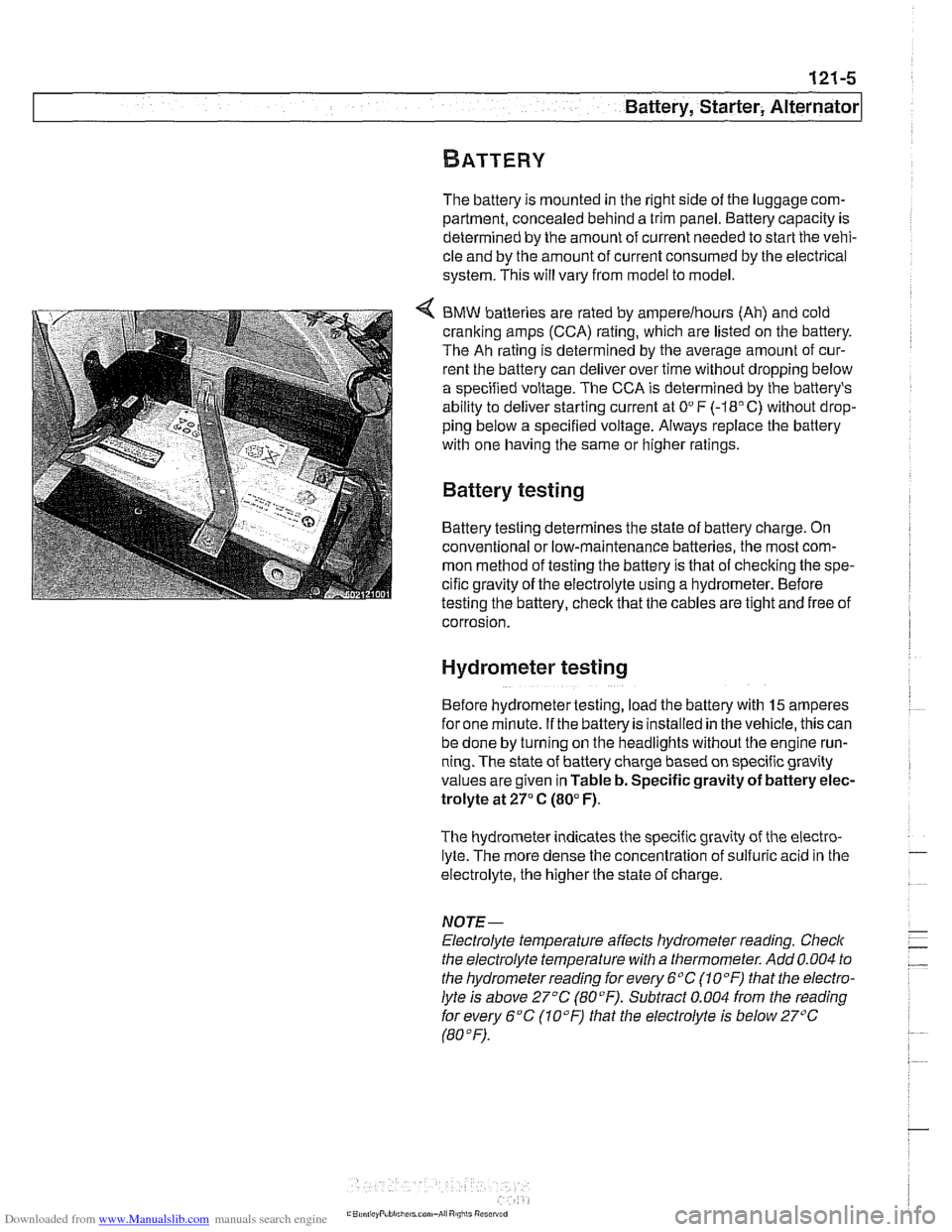
The battery is mounted in the right side of the luggage com-
partment, concealed behind a trim panel. Battery capacity is
determined by the amount of current needed to start the vehi-
cle and by the amount of current consumed by the electrical
system. This will vary from model to model.
BMW batteries are rated by
amperelhours (Ah) and cold
cranking amps (CCA) rating, which are listed on the battery.
The Ah rating is determined by the average amount of cur-
rent the battery can deliver over time without dropping below
a specified voltage. The CCA is determined by the battery's
ability to deliver starting current at
On F (-18" C) without drop-
ping below a specified voltage. Always replace the battery
with one having the same or higher ratings.
Battery testing
Battery testing determines the state of battery charge. On
conventional or low-maintenance batteries. the most com-
mon method of testing the battery is that
ofchecking the spe-
cific gravity of the electrolyte using a hydrometer. Before
testing the battery, check that the cables are tight and free of
- corrosion.
Hydrometer testing
Before hydrometertesting, load the battery with 15 amperes
for one minute. If the battery is installed in the vehicle, this can
be done by turning on the headlights without the engine run-
ning. The state of battery charge based on specific gravity
values are given in Table
b. Specific gravity of battery elec-
trolyte at
27" C (80°F).
The hydrometer indicates the specific gravity of the electro-
lyte. The more dense the concentration of sulfuric acid in the
electrolyte, the higher the state of charge
NOTE-
Electrolyte temperature affects hydrometer reading. Checlc
the electrolyte temperature with a thermometer. Add 0.004 to
the hydrometerreading
forevery 6°C (10°F) that the electro-
lyte is above 27°C
(80°F). Subtract 0.004 from the reading
forevery 6°C (10°F) that the electrolyte is below27"C
(80°F).
Page 372 of 1002
Downloaded from www.Manualslib.com manuals search engine
.
Battery, Starter, Alternator
Table b. Specific gravity of battery electrolyte at 27°C (80°F)
Specific gravity State of charge
1.265 Fully charged
1.225 75% charged
1.190 50% charged
1.155 25% charged
1.120 Fully discharged
if the specific gravity is at
orabove 1.225, butthe battery lacks
Dower for
startinq, determine the battew's service condition
with a load volta& test. if the average specific gravity of the
six cells is below 1.225, remove the battery from the luggage
compartment and recharge.
Battery open-circuit voltage test
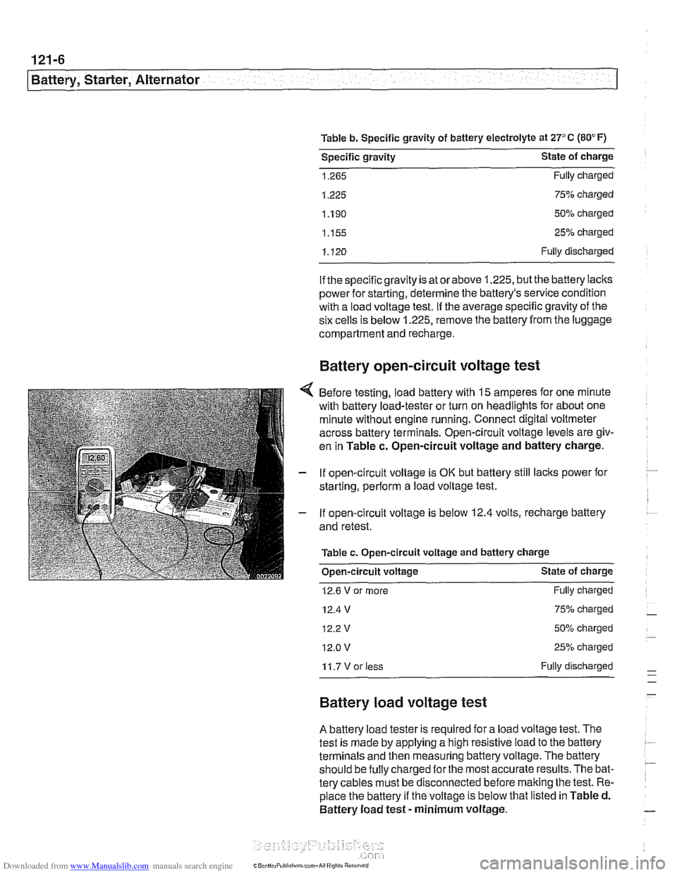
Before testing, load battery with 15 amperes for one minute
with battery load-tester or turn on headlights for about one
minute without engine running. Connect digital voltmeter
across battery terminals. Open-circuit voltage levels are giv-
en in Table
c. Open-circuit voltage and battery charge.
If open-circuit voltage is
OK but battery still lacks power for
starting, perform a load voltage test.
If open-circuit voltage is
below 12.4 volts, recharge battery
and retest.
Table c. Open-circuit voltage and battery charge
Open-circuit voltage State of charge
12.6 V or more
12.4 V
12.2v
12.0 v
Fully charged
75% charged
50% charged
25% charged
11.7Vorless Fully discharged
Battery load voltage test
A battery load tester is required for a load voltage test. The
test is made by applying a high resistive load to the battery
terminals and then measuring battery voltage. The battery
should be
fully charged forthe most accurate results. The bat-
tery cables must be disconnected before
malting the test. Re-
place the battery if the voltage is below that listed in Table d.
Battery load test
- minimum voltage.