high BMW 540i 2001 E39 Service Manual
[x] Cancel search | Manufacturer: BMW, Model Year: 2001, Model line: 540i, Model: BMW 540i 2001 E39Pages: 1002
Page 475 of 1002
Downloaded from www.Manualslib.com manuals search engine
Fuel Tank and Fuel Pump
Warnings and cautions
Observe the following warnings and cautions when servicing
the fuel system.
WARNING-
* The fuel system is designed to retain pressure even when
the ignition is off. When working with the fuelsystem, loos-
en the fuel lines slowly to allow residual
fuel pressure to
dissipate. Avoid spraying fuel. Use shop rags to capture
leaking fuel.
Before beginning any work on the fuel system, place a
fire extinguisher in the vicinity of the work area.
Fuel is highly flammable. When working around fuel, do
not disconnect any wires that could cause electrical
sparks. Do not smoke or worknearheaters or other fire
hazards.
* Always unscrew the fuel tank cap to release pressure
in the
tanlc before working on the tank or lines.
When disconnecting a fuel hose, wrap shop rag around
end of hose to prevent spray of fuel under pressure.
Do not use a work light with an incandescent bulb near
any fuel. Fuel may spray on the hot bulb causing a fire.
0 Make sure the worlc area is properly ventilated.
CAUTION-
- Prior to disconnecting the battery, read the battery discon-
nection cautions given in
001 General Cautions an4
Warnings.
Before
making any electrical tests with the ignition
turned on, disable the ignition system as described in
120 Ignition System. Be sure the battery is discon-
nected when replacing components.
To prevent damage to the ignition system or other DME
components, including the engine control module
(ECM), always connect and disconnect wires and test
equipment with the ignition off.
Cleanliness is essential when
worl~ing with the fuel sys-
tem. Thoroughly clean the fuel line unions before dis-
connecting any of the lines.
Use only clean tools. Keep removed parts clean and
sealed or covered with a clean, lint-free cloth, especial-
ly if completion of the repair is delayed.
Do not move the car while the fuel system is open.
Avoid using high pressure compressed air to blow out
lines and components. High pressure can rupture inter-
nal seals and gaskets.
Always replace seals, O-rings and hose clamps.
Page 479 of 1002
Downloaded from www.Manualslib.com manuals search engine
.- -
Fuel Tank and Fuel purnpl
Fuel pump power consumption, testing
To achieve accurate test results, the battery voltage at the
fuel pump connector should be
12.6 volts. Charge the battery
as necessary.
A higher than normal power consumption may indicate a
worn fuel pump, which may cause intermittent fuel starvation
due to pump overheating and seizure. The only remedy is
pump replacement.
A lower than normal power consumption
may indicate a blockage. Be sure to check that the return line
and the pump pickup are not obstructed before replacing the
pump.
- Expose right side access cover:
Peel forward lip of carpet.
Release rubber grommet from center of access cover insu-
lation.
Peel back insulation at perforations to expose fuel tank ac-
cess cover.
Remove right side cover to expose electrical harness con-
nector.
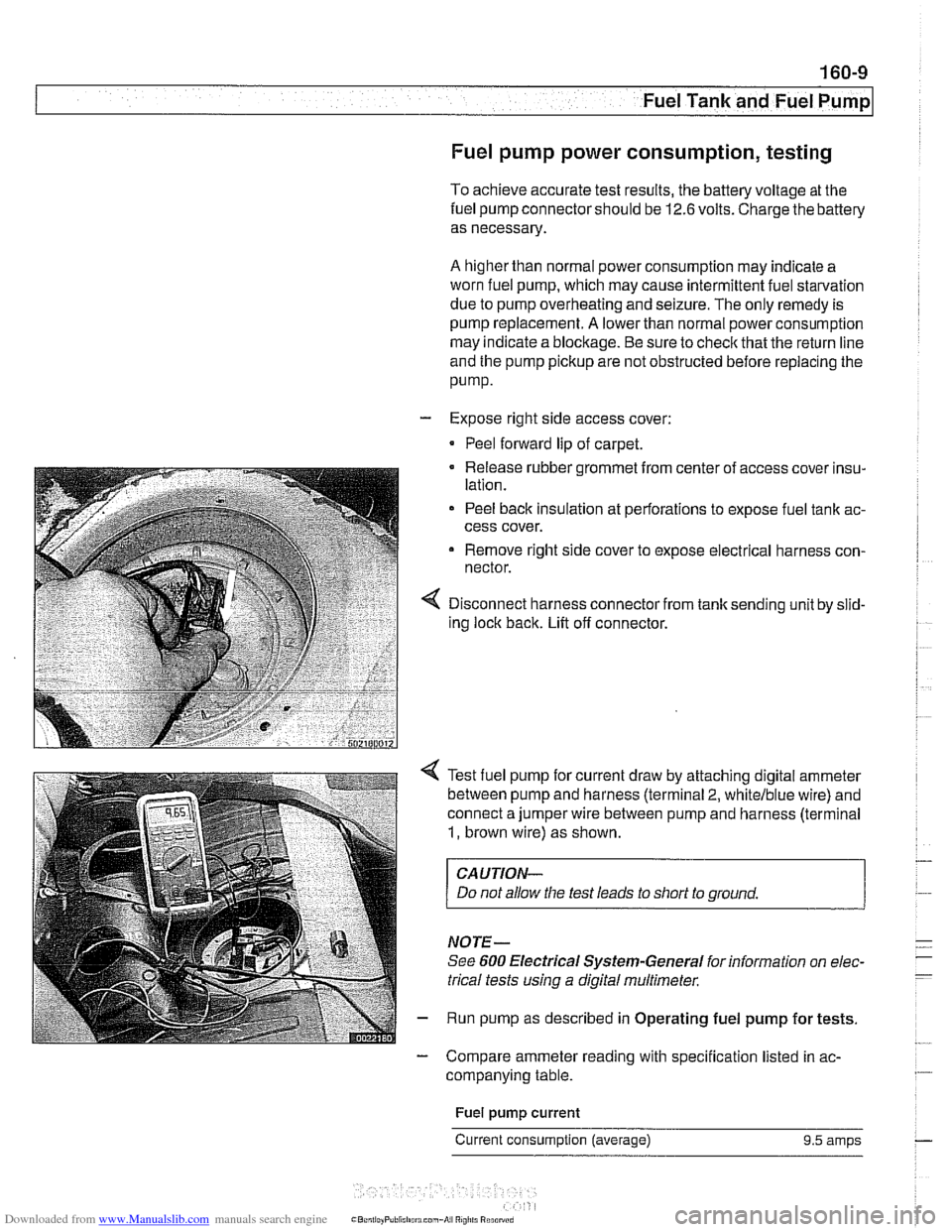
Disconnect harness connector from tank sending unit by slid-
ing lock back. Lift off connector.
Test fuel pump for current draw by attaching digital ammeter
between pump and harness (terminal
2, whitelblue wire) and
connect a jumper wire between pump and harness (terminal
1, brown wire) as shown.
CAUTION-
Do not allow the test leads to short to ground.
NOTE-
See 600 Electrical Systern-General for information on elec-
trical tests
using a digital multirneter.
Run pump as described in Operating fuel pump for tests.
- Compare ammeter reading with specification listed in ac-
companying table.
Fuel
pump current
Current consumption (average) 9.5 amps
Page 483 of 1002
Downloaded from www.Manualslib.com manuals search engine
Fuel Tank and Fuel Pump
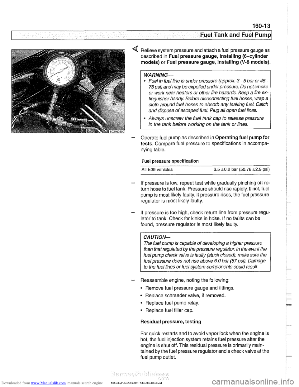
4 Relieve system pressure and attach a fuel pressure gauge as
described in Fuel pressure gauge, installing (6-cylinder
models) or Fuel pressure gauge, installing
(V-8 models).
WARNING-
Fuel in fuel line is under pressure (approx. 3 - 5 bar or 45 -
75psi) and may be expelled underpressure. Do not smoke
or
worlc near heaters or other fire hazards. Keep a fire ex-
tinguisher handy Before disconnecting fuel hoses, wrap a
cloth around fuel hoses to absorb any
leaking fuel. Catch
and dispose of escaped fuel. Plug all open fuel lines.
Always unscrew the fuel tank cap to release pressure
in the tank before
working on the tank or lines.
- Operate fuel pump as described in Operating fuel pump for
tests. Compare fuel pressure to specifications in accompa-
nying table.
Fuel pressure specification
All E39 vehicles 3.5 +0.2 bar (50.76 i2.9 psi)
- If pressure is low, repeat test while gradually pinching off re-
turn hose to fuel tank. Pressure should rise rapidly. If not, fuel
pump is most likely faulty. If pressure rises, the fuel pressure
regulator is most
likely faulty.
- If pressure is too high, checlc return line from pressure regu-
lator to tank. Check for
ltinks in hose. If no faults can be
found, pressure regulator is most likely faulty.
CAUTION-
The fuel pump is capable of developing a higher pressure
than that regulated by the pressure regulator. In the event the
fuel pump checlc valve is faulty (stuck closed), male sure the
I fuel pressure does not rise above 6.0 bar (87psi). Damage
to the fuel lines or fuel system components could result.
- Reassemble engine, noting the following:
Remove fuel pressure gauge and fittings.
Replace schraeder valve, if removed
Replace fuel pump relay.
Replace fuel filler cap.
Residual pressure, testing
For quick restarts and to avoid vapor lock when the engine is
hot, the fuel injection system retains fuel pressure after the
engine is shut off. This residual pressure is primarily
rnain-
tained by the fuel pressure regulator and a checlc valve at the
fuel pump
outlet.
Page 500 of 1002
Downloaded from www.Manualslib.com manuals search engine
-
I Radiator and Cooling System
Mechanical thermostat
(M52 engine)
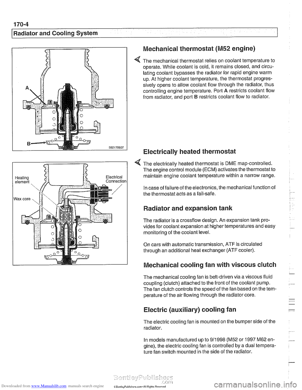
4 The mechanical thermostat relies on coolant temperature to
operate. While coolant is cold, it remains closed, and circu-
lating coolant bypasses the radiator for rapid engine warm
up. At higher coolant temperature, the thermostat progres-
sively opens to allow coolant flow through the radiator, thus
controlling engine temperature. Port
A restricts coolant flow
from radiator, and port
B restricts coolant flow to radiator.
Electrically heated thermostat
4 The electrically heated thermostat is DME map-controlled.
The engine control module (ECM) activates the thermostat to
maintain engine coolant temperature within a narrow range.
In case of failure of the electronics, the mechanical function of
the thermostat acts as a fail-safe.
Radiator and expansion tank
The radiator is a crossflow design. An expansion tank pro-
vides for coolant expansion at higher temperatures and easy
monitoring of the coolant level.
On cars with automatic transmission, ATF is circulated
through an additional heat exchanger (ATF cooler).
Mechanical cooling fan with viscous clutch
The mechanical cooling fan is belt-driven via a viscous fluid
coupling (clutch) attached to the front of the coolant pump.
The fan clutch controls the speed of the fan based on the tem-
perature of the air flowing through the radiator core.
Electric (auxiliary) cooling fan
The electric cooling fan is mounted on the bumper side of the
radiator.
In models manufactured up to
911 998 (M52 or 1997 M62 en-
gine), the electric cooling fan is controlled by a dual tempera-
ture fan switch mounted in the side of the radiator.
Page 501 of 1002
Downloaded from www.Manualslib.com manuals search engine
170-5
Radiator and Cooling System
Fan switch calibration (M52, M62 engine)
coniprairoi OUt rlgnal
Auto. ciimilte ~ontioi inpuls via CAN bus
Electric fan activation:
Low speed
91°C (196°F)
High speed 104' C (21 9' F)
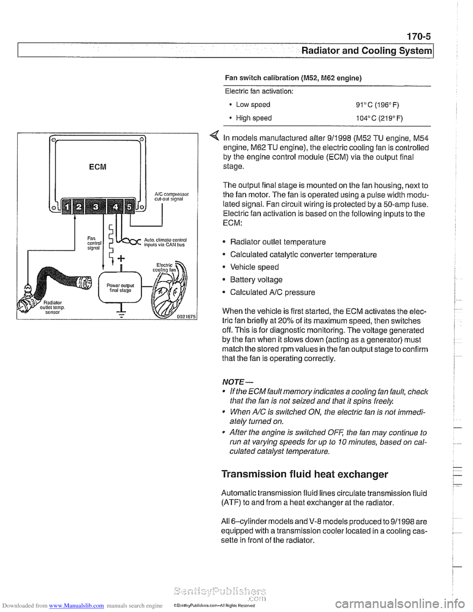
< In models manufactured after 911998 (M52 TU engine, M54
engine.
M62 TU engine), the electric cooling fan is controlled
by the engine control module (ECM) via the output final
stage.
The output final stage is mounted on the fan housing, next to
the fan motor. The fan is operated using a pulse width modu-
lated signal. Fan circuit wiring is protected by a 50-amp fuse.
Electric fan activation is based on the following inputs to the
ECM:
Radiator outlet temperature
Calculated catalytic converter temperature
Vehicle speed
* Battery voltage
Calculated
A/C pressure
When the vehicle is first started, the ECM activates the elec-
tric fan briefly at 20% of its maximum speed, then switches
off. This is for diagnostic monitoring. The voltage generated
by the fan when it slows down (acting as a generator) must
match the stored rpm values in the fan output stage toconfirm
that the fan is operating correctly.
NOTE-
If the ECM fault memory indicates a cooling fan fault, check
that the fan is not seized and that it spins freely.
When
A/C is switched ON, the electric fan is not immedi-
ately turned on.
After the engine is switched
OFF the fan may continue to
run at varying speeds for up to 10 minutes, based on cal-
culated catalyst temperature.
Transmission fluid heat exchanger
Automatic transmission fluid lines circulate transmission fluid
(ATF) to and from a heat exchanger at the radiator.
All 6-cylinder
models andV-8 models produced to 911998 are
equipped with a transmission cooler located in a cooling cas-
sette in front of the radiator.
Page 524 of 1002
Downloaded from www.Manualslib.com manuals search engine
180-2
Exhaust System
The exhaust system is designed to be maintenance free, al-
though regular inspection is warranted due to the harsh oper-
ating conditions. Under normal conditions, the catalytic
converter does not require replacement unless it is damaged.
New fasteners, clamps, rubber mounts and gaskets should
be used when replacing exhaust components.
A liberal appli-
cation of penetrating oil to the exhaust system nuts and bolts
in advance may make removal easier.
WARNING -
The exhaust system and catalytic converter operate at
very high temperatures. Allow components to cool before
servicing. Wear protective clothing to prevent burns.
Do not use flammable chemicals near a hot
cataiyiic
converter.
Corroded exhaust system components crumble easily
and often have exposed sharp edges. To avoid injury,
wear eye protection and heavy gloves when working
Exhaust system, removing and installing
The removal and installation procedures given here are gen-
eral procedures for all models. The removal of the exhaust
system as a complete unit is recommended. Once the com-
plete system is removed from the car, individual pipes and
mufflers can be more easily replaced.
WARNING-
Exhaust gases are colorless, odorless, and very toxic. Run
the engine only in a well-ventilated area. Immediately repair
any
leaks in the exhaust system or structural damage to the
car body that
might allow exhaust gases to enter the passen-
ger compartment.
CAUTION-
Use care not to drag or bang oxygen sensors. Oxygen sen-
sors can be easily ruined.
Page 530 of 1002
Downloaded from www.Manualslib.com manuals search engine
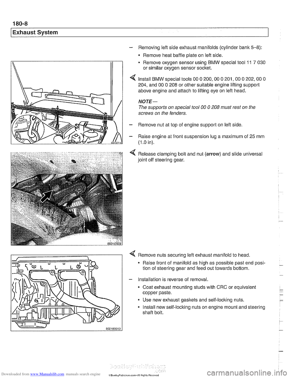
- Removing left side exhaust manifolds (cylinder bank 5-8):
- Remove heat baffle plate on left side.
Remove oxygen sensor using
BMW special tool 11 7 030
or similar oxygen sensor socket.
Install
BMW special tools 00 0 200,OO 0 201,OO 0 202,OO 0
204, and 00 0 208 or other suitable engine lifting support
above engine and attach to lifting eye on left head.
NOTE-
The supports on special tool 00 0 208 must rest on the
screws on the fenders.
- Remove nut at top of engine support on left side
- Raise engine at front suspension lug a maximum of 25 mm
(I
.O in).
Release clamping bolt and nut
(arrow) and slide universal
joint off steering gear.
4 Remove nuts securing left exhaust manifold to head,
Raise front of manifold as high as possible past end posi-
tion of steering gear and feed out towards bottom.
- Installation is reverse of removal.
Coat exhaust mounting studs with CRC or equivalent
copper paste.
Use new exhaust gaskets and self-locking nuts.
Install new self-locking nuts on engine mount and steering
shaft bolt.
Page 547 of 1002
Downloaded from www.Manualslib.com manuals search engine
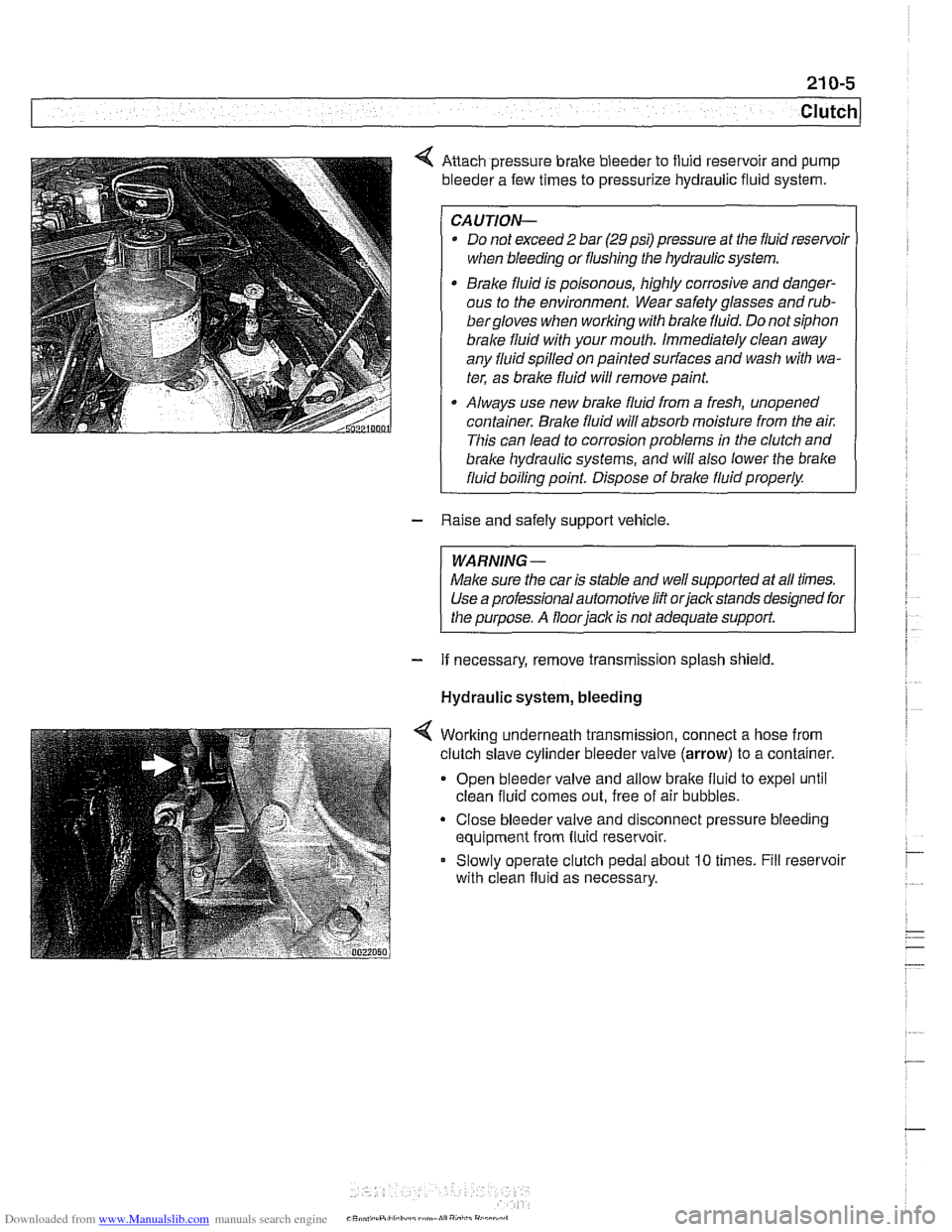
Anach pressure brake bleeder to fluid reservoir and pump
bleeder a few times to pressurize hydraulic fluid system.
CAUTION-
* Do not exceed 2 bar (29 psi) pressure at the fluid resenfoil
when bleeding or flushing the hydraulic system.
Brake fluid is poisonous, highly corrosive and danger-
ous to the environment. Wear safety glasses and
rub-
bergloves when working with brake fluid. Do not siphon
brale fluid with your mouth. Immediately clean away
any fluid spilled on painted surfaces and wash with wa-
ter, as brale fluid will remove paint.
Always use new brake fluid from a fresh, unopened
container.
Brake fluid will absorb moisture from the air.
This can lead to corrosion problems in the clutch and
brake hydraulic systems, ;nd will also lower the brake
fluid boiling point. Dispose of brale fluid properly.
- Raise and safely support vehicle.
WARNING-
Make sure the car is stable and well supported at all times.
Use a professional automotive lift orjackstands designed for
the purpose. A floor
iack is not adequate support.
- If necessary, remove transmission splash shield.
Hydraulic system, bleeding
Worlting underneath transmission, connect a hose from
clutch slave cylinder bleeder valve
(arrow) to a container.
Open bleeder valve and allow bralte fluid to expel until
clean fluid comes out, free of air bubbles.
Close bleeder valve and disconnect pressure bleeding
equipment from fluid reservoir.
Slowly operate clutch pedal about
10 times. Fill reservoir
with clean fluid as necessary.
CR* .,,, .rP,ll,h.:I,,~,~mn.lI","i,,i"
Page 548 of 1002
Downloaded from www.Manualslib.com manuals search engine
21 0-6
1 Clutch
Hydraulic system, bleeding
(using
BMW special tool 21 5 030)
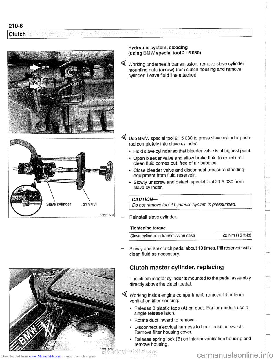
4 Working underneath transmission, remove slave cylinder
mounting nuts (arrow) from clutch housing and remove
cylinder. Leave fluid line attached.
4 Use BMW special tool 21 5 030 to press slave cylinder push-
rod completely into slave cylinder.
Hold slave cylinder so that bleeder valve is at highest point.
Open bleeder valve and allow brake fluid to expel until
clean fluid comes out, free of air bubbles.
* Close bleeder valve and disconnect pressure bleeding
equipment from fluid reservoir.
Slowly unscrew and detach special tool 21
5 030 from
slave cylinder.
CAUTION-
Do not remove tool if hydraulic system is pressurized.
- Reinstall slave cylinder.
Tightening torque Slave cylinder to transmission case
22 Nm (1 6 ft-lb)
- Slowly operate clutch pedal about 10 times. Fill reservoir with
clean fluid as necessary.
Clutch master cylinder, replacing
The clutch master cylinder is mounted to the pedal assembly
directly above the clutch pedal.
Working inside engine compartment, remove left interior
ventilation filter housing:
Release 3 plastic taps
(A) on duct. Earlier models use a
single release latch.
Rotate duct inward to remove
Disconnect electrical harness to hood position switch.
Remove filter housing cover.
Release spring
loclc (B) on interior ventilation housing and
remove housing.
Page 662 of 1002
Downloaded from www.Manualslib.com manuals search engine
I Steerina and Wheel Alianment
Steering
system
Two types of steering gear are used in the E39 series models.
6-cylinder
(5251, 528i and 530i) models are equipped with
rack and pinion steering. The steering rack is mounted to
an aluminum subframe.
V-8
(540i) models are equipped with a recirculating ball
and nut steering gearbox mounted to a steel subframe.
At low speeds, maximum power assist is provided to ease
parking and city driving. At high speeds, assist is reduced to
ensure stability. The power steering system varies assist
based on engine speed.
Power boost for the steering is provided by an engine-driven
hydraulic pump. A hydraulic control valve is used to control
boost pressure.
The steering wheel connects to the steering gear via an ad-
justable steering column which incorporates a rubber cou-
pling ("guibo") to dampen vibration and noise.
Power steering fluid is supplied from the fluid
reservoir to the
pump and to the steering gear via rubberlmetal hoses.
The return line from the steering gear to the
reservoir loops
into the airstream in front of the radiator and connects to the
steering fluid cooler. The fluid cooler is attached to a cassette
which also includes cooling coils for engine oil, transmission
fluid and AIC condenser.
The steering gear requires no maintenance other than align-
ment and periodic inspection for worn components. Inspect
rubber rack boots
(rack and pinion system) and tie-rod end
boots periodically for tears or damage. Replace
if necessary.
-
NOTE-
The airbag system is traditionally referred to as Supplemen-
tal Restraint System (SRS). The
BMW versfon of SRS used
m the E39 models is known as the Multiple Restraint System - (MRS). - -