change time BMW M4 2016 Owners Manual
[x] Cancel search | Manufacturer: BMW, Model Year: 2016, Model line: M4, Model: BMW M4 2016Pages: 228, PDF Size: 4.88 MB
Page 12 of 228
CockpitVehicle equipment
This chapter describes all standard, national
and special equipment provided in the model
series. Equipment not available in the vehicle is
therefore also described, for example the se‐lected special equipment or national version.
This also applies to safety-relevant functions
and systems. Comply with the relevant na‐
tional regulations when using the correspond‐
ing functions and systems.
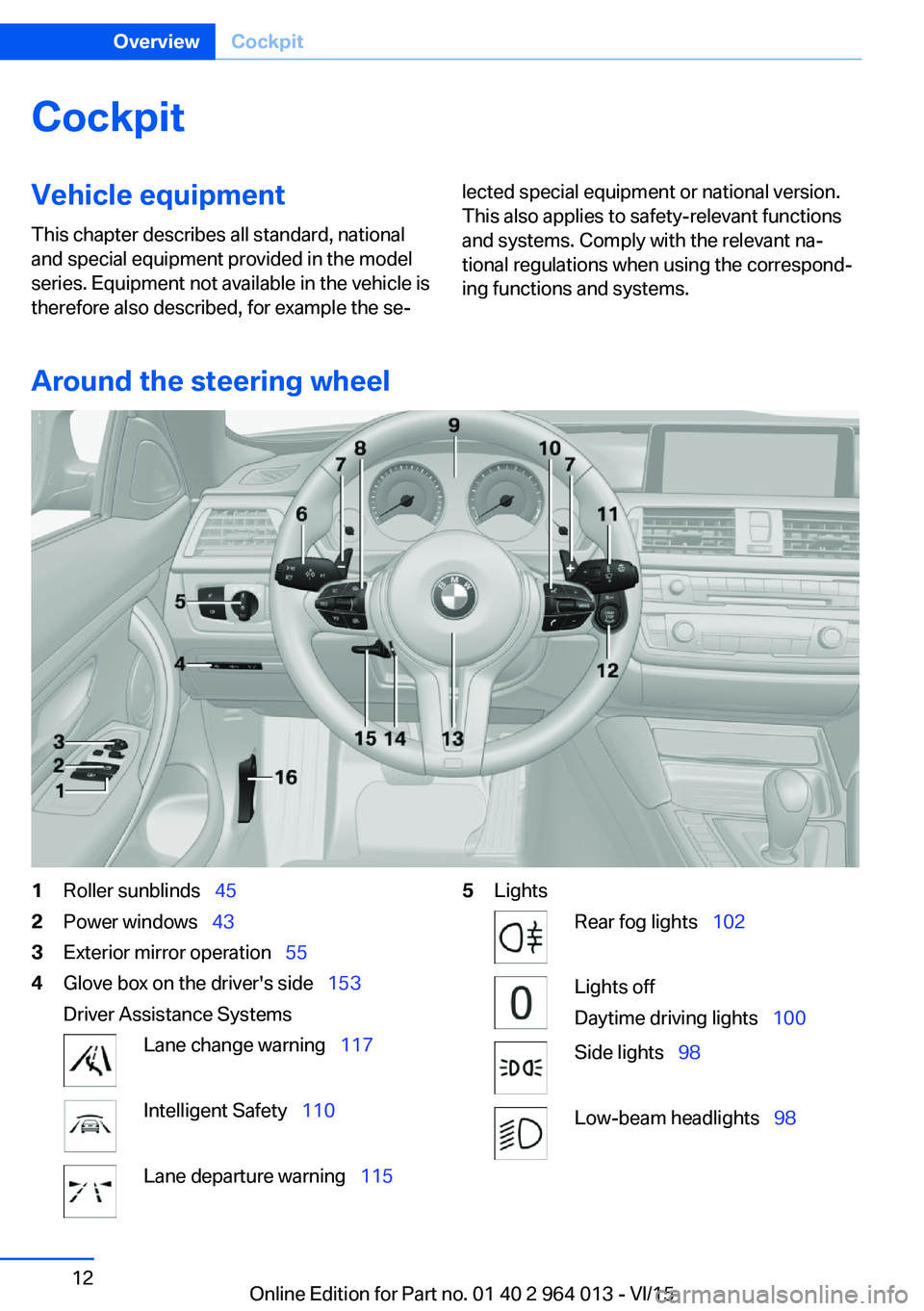
Around the steering wheel
1Roller sunblinds 452Power windows 433Exterior mirror operation 554Glove box on the driver's side 153
Driver Assistance SystemsLane change warning 117Intelligent Safety 110Lane departure warning 1155LightsRear fog lights 102Lights off
Daytime driving lights 100Side lights 98Low-beam headlights 98Seite 12OverviewCockpit12
Online Edition for Part no. 01 40 2 964 013 - VI/15
Page 20 of 228
▷The system recognises capital and small
letters. To enter small and capital letters
and numbers, it may be necessary to the
change input mode, for example, when
identically writing small and capital letters.
Change between upper/lower case, num‐
bers and symbols, see page 23.▷Enter symbols as they are displayed on the
Control Display.▷Relevant symbols, such as accents or full
stops are always known ambiguously with
the letter. The input option depends on the
language that has been set. You may need
to enter special characters using the Con‐
troller.▷To delete a character, swipe the touchpad
towards the left.▷To enter a space, swipe towards the right
in the middle of the touchpad.▷To enter a hyphen, swipe towards the right
in the upper area of the touchpad.▷To enter an underscore, swipe towards the
right in the lower area of the touchpad.
Operating interactive map and
Internet
The Interactive map of the navigation system
and websites can be moved using the touch‐
pad.
FunctionControlsMove interactive map or
web pages.Swipe in the ap‐
propriate direction.Enlarge/reduce interac‐
tive map or web pages.Pinch or open up
your fingers on the
touchpad.Show menu or open a
link on the Internet.Tap once.
Adjusting the settings
Settings on the Control Display, such as vol‐
ume, for example, can be made using the
touchpad. To do this swipe left or right as ap‐
propriate.
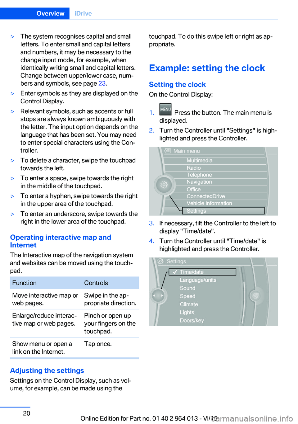
Example: setting the clock Setting the clock
On the Control Display:1. Press the button. The main menu is
displayed.2.Turn the Controller until "Settings" is high‐
lighted and press the Controller.3.If necessary, tilt the Controller to the left to
display "Time/date".4.Turn the Controller until "Time/date" is
highlighted and press the Controller.Seite 20OverviewiDrive20
Online Edition for Part no. 01 40 2 964 013 - VI/15
Page 42 of 228
Boot lid is opened and doors are un‐
locked.
Acknowledgement signal of the
vehicle
Settings are saved in active profile, see
page 33.
1."Settings"2."Doors/key"3."Turn signals for lock/unl."
Automatic locking
Settings are saved in active profile, seepage 33.
1."Settings"2."Doors/key"3.Select the desired function:▷"Automatic relock"
The vehicle is locked automatically af‐
ter a short while if no door is opened.▷"Lock after driving away"
On driving off, the vehicle is locked au‐
tomatically.
Calling up seat, mirror setting
The last adjusted driver's seat and exterior mir‐
ror position is saved for the currently used re‐
mote control.
When the vehicle is unlocked, this position is
called up automatically if the function has been
enabled.
WARNING
Danger of trapping when moving the
seats. Danger of injury or damage to property.
Before making the setting, make sure that the
movement area of the seat is clear.◀
Adjustment procedure is interrupted:
▷By operating the switch or the seat adjust‐
ment.▷By touching a button of the seat and mirror
memory.
Enabling setting
1."Settings"2."Doors/key"3."Last seat position autom."
Alarm system
PrincipleThe alarm system is triggered when the vehi‐cle is locked if:
▷A door, the bonnet or the the boot lid is
opened.▷Movements in the interior.▷The vehicle's incline changes, for instance
if an attempt is made to jack it up and steal
the wheels or to raise it prior to towing
away.▷There is an interruption in the power sup‐
ply from the battery.
The alarm system will respond briefly to unau‐
thorised attempts to access the vehicle as fol‐
lows:
▷Acoustic alarm.▷Switching on the hazard warning lights.
Arming and disarming
At the same time as unlocking and locking the
vehicle by remote control or Comfort Access
the alarm system is also disarmed or armed.
Door lock with alarm system armed Alarm system is deactivated if the vehicle is
unlocked using the door lock.
Boot lid with alarm system armed The boot lid can be opened even with the
alarm system armed.
Seite 42ControlsOpening and closing42
Online Edition for Part no. 01 40 2 964 013 - VI/15
Page 61 of 228
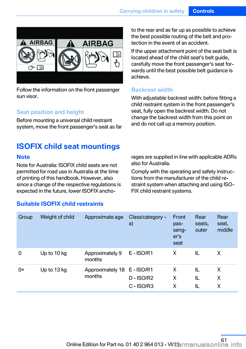
Follow the information on the front passenger
sun visor.
Seat position and height
Before mounting a universal child restraint
system, move the front passenger's seat as far
to the rear and as far up as possible to achieve
the best possible routing of the belt and pro‐
tection in the event of an accident.
If the upper attachment point of the seat belt is
located ahead of the child seat's belt guide,
carefully move the front passenger's seat for‐
wards until the best possible belt guidance is
achieve.
Backrest width With adjustable backrest width: before fitting a
child restraint system in the front passenger's
seat, fully open the backrest width. Do not
change the backrest width from this point on
and do not call up a memory position.
ISOFIX child seat mountings
Note
Note for Australia: ISOFIX child seats are not
permitted for road use in Australia at the time
of printing of this handbook. However, also
since a change of the respective regulations is
expected in the future, lower ISOFIX ancho‐rages are supplied in line with applicable ADRs
also for Australia.
Comply with the operating and safety instruc‐
tions from the manufacturer of the child re‐
straint system when attaching and using ISO‐
FIX child restraint systems.
Suitable ISOFIX child restraints
GroupWeight of childApproximate ageClass/category –
a)Front
pas‐
seng‐
er's
seatRear
seats,
outerRear
seat,
middle0Up to 10 kgApproximately 9
monthsE - ISO/R1XILX0+Up to 13 kgApproximately 18
monthsE - ISO/R1
D - ISO/R2
C - ISO/R3X
X
XIL
IL
ILX
X
XSeite 61Carrying children in safetyControls61
Online Edition for Part no. 01 40 2 964 013 - VI/15
Page 65 of 228
DrivingVehicle equipment
This chapter describes all standard, national
and special equipment provided in the model
series. Equipment not available in the vehicle is
therefore also described, for example the se‐
lected special equipment or national version.
This also applies to safety-relevant functions
and systems. Comply with the relevant na‐
tional regulations when using the correspond‐
ing functions and systems.
Start/stop button
Principle The ignition is switched on or offand the engine is started by
pressing the start/stop button.
M double clutch transmission:
The engine starts if the brakes
are applied when the start-stop button is
pressed.
Manual gearbox: The engine starts if the clutch
pedal is pressed when pressing the start/stop
button.
Ignition on M double clutch transmission: Press the start/
stop button without applying the brakes.
Manual gearbox: Press the start/stop button,
do not press the clutch pedal.
All systems are operational.
Most of the indicator and warning lamps in the
instrument cluster are illuminated for different
lengths of time.
To save battery power when the engine is off,
switch off the ignition and any unnecessary
electronic systems.Ignition off
M double clutch transmission: Press the start/
stop button again without applying the brakes.
Manual gearbox: Press the start/stop button
again, do not press the clutch pedal.
All indicator lights in the instrument cluster ex‐
tinguish.
To save battery power when the engine is off,
switch off the ignition and any unnecessary
electronic systems.
Notes
When the ignition is switched off, selector
lever position P will be automatically engaged,
if selector lever position D or R is engaged.
With the vehicle stationary and the engine shut
down, the ignition is switched off automatically
under the following circumstances:▷When locking, even with the low-beam
headlights switched on.▷Shortly before the battery is discharged so
that an engine start remains possible.▷When opening or closing the driver's door,
if the driver's belt is unfastened and the
low-beam headlights are switched off.▷When the driver's belt is unfastened, if the
driver's door is opened and the low-beam
headlights switched off.
After about 15 minutes without further opera‐
tion, low-beam headlights are changed over to
side lights.
Radio ready state
Activate radio ready state: when the engine is
running, press the start/stop button.
Individual electrical systems remain opera‐
tional.
The radio ready sate is automatically switched
off in the following situations:
Seite 65DrivingControls65
Online Edition for Part no. 01 40 2 964 013 - VI/15
Page 66 of 228
▷After approximately eight minutes.▷When locking via the central locking sys‐
tem.▷Shortly before the battery is discharged so
that an engine start remains possible.
Radio readiness remains active when ignition
is switched off automatically, such as for
following reasons:
▷Opening or closing driver's door.▷Unfastening driver's seat belt.▷When low-beam headlights are automati‐
cally changed to side lights.
If engine is switched off and ignition is
switched on, radio ready state will be automati‐
cally activated when door is opened if light is
switched off or daytime driving lights are
switched on, when corresponding equipment
is fitted.
Engine start Notes DANGER
A blocked exhaust pipe or inadequate
ventilation can allow harmful exhaust fumes to
penetrate the vehicle. The exhaust gas con‐
tains carbon monoxide, which is colourless and
odourless, but highly toxic. In enclosed spaces,
the exhaust fumes can also build up outside
the vehicle. Danger of fatal injury. Keep the ex‐
haust pipe clear and ensure sufficient ventila‐
tion.◀
WARNING
An unsecured vehicle can start moving
and rolling away. Danger of accidents. Before
leaving the vehicle, secure it to prevent rolling
away.
Observe the following to ensure that the vehi‐
cle is secured against rolling away:
▷Engage the parking brake.▷Turn the front wheels into the direction of
the kerb on upward or downward gradi‐
ents.▷Additionally secure the vehicle on upward
or downward gradients, e.g. using a
wedge.◀
ATTENTION
Repeated start attempts or starting sev‐
eral times in quick succession means that fuel
is not combusted, or insufficiently so. The cat‐
alytic converter can overheat. Danger of dam‐
age to property. Avoid starting more than once
in quick succession.◀
M double clutch transmission
Starting the engine
1.Press the brake.2.Press the start/stop button.
Starting proceeds for a certain time automati‐
cally and stops as soon as the engine is star‐
ted.
Manual gearbox
Starting the engine
1.Press the brake.2.Depress the clutch and engage idle posi‐
tion.3.Press the start/stop button.
Starting proceeds for a certain time automati‐
cally and stops as soon as the engine is star‐
ted.
Seite 66ControlsDriving66
Online Edition for Part no. 01 40 2 964 013 - VI/15
Page 74 of 228
Reverse gear
Engage this position only when the vehicle is
stationary.
To overcome the resistance of the selector
lever move in a dynamic movement towards
the left and engage the reverse gear.
M double clutch
transmission with Drivelogic
General The M double clutch transmission with Drive‐
logic is an automated manual gearbox with two
clutches and partial gears, by which the gears
are changed without interrupting traction.
It is operated using the selector lever or two
paddles on the steering wheel.
Functions▷Drive mode or sequential mode.▷Various drive programs, Drivelogic.▷Shift Lights, see page 96▷Automatic downshift and protection
against shifting even in sequential mode.▷Launch Control.▷Low Speed Assistant.
Selector lever, selector lever position
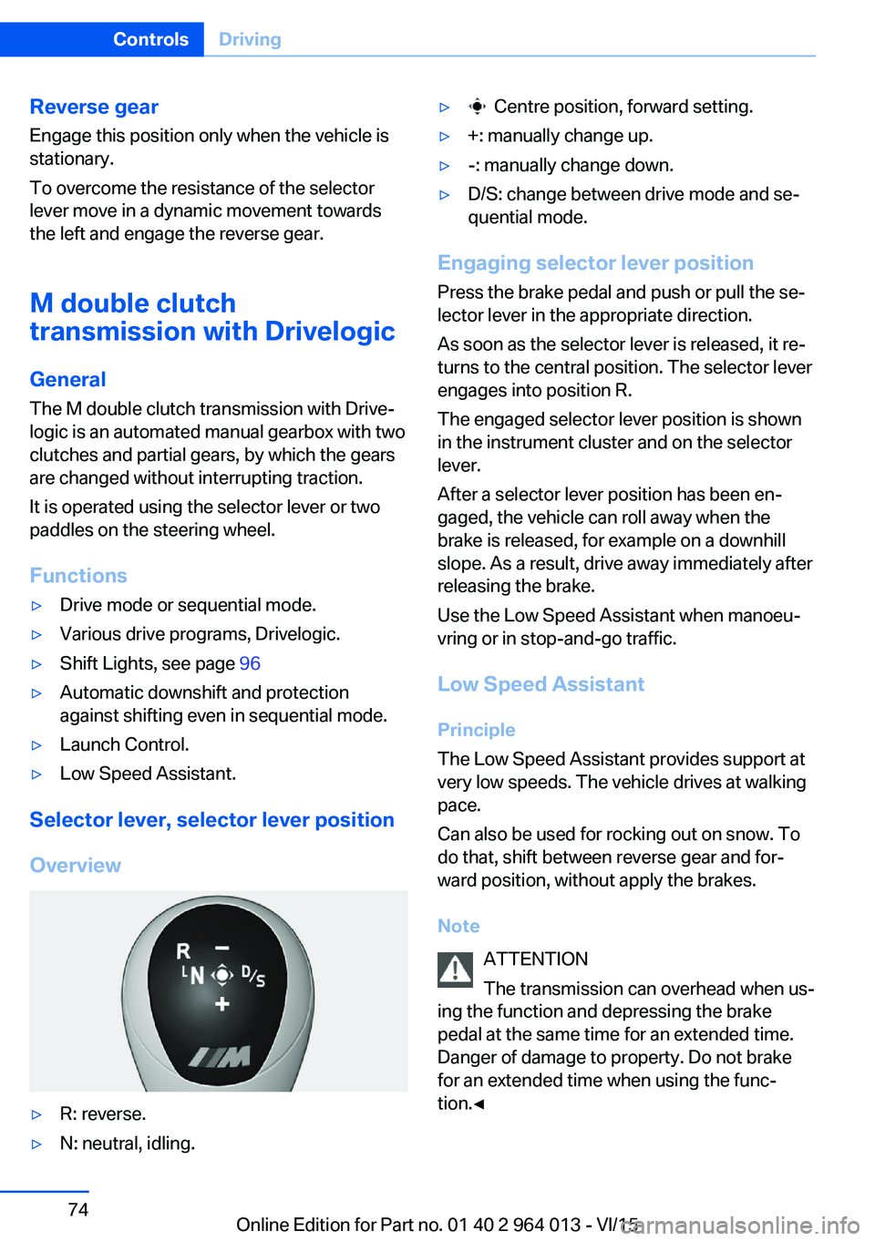
Overview
▷R: reverse.▷N: neutral, idling.▷ Centre position, forward setting.▷+: manually change up.▷-: manually change down.▷D/S: change between drive mode and se‐
quential mode.
Engaging selector lever position
Press the brake pedal and push or pull the se‐
lector lever in the appropriate direction.
As soon as the selector lever is released, it re‐
turns to the central position. The selector lever
engages into position R.
The engaged selector lever position is shown
in the instrument cluster and on the selector
lever.
After a selector lever position has been en‐
gaged, the vehicle can roll away when the
brake is released, for example on a downhill
slope. As a result, drive away immediately after
releasing the brake.
Use the Low Speed Assistant when manoeu‐
vring or in stop-and-go traffic.
Low Speed Assistant
Principle
The Low Speed Assistant provides support at
very low speeds. The vehicle drives at walking
pace.
Can also be used for rocking out on snow. To
do that, shift between reverse gear and for‐
ward position, without apply the brakes.
Note ATTENTION
The transmission can overhead when us‐
ing the function and depressing the brake
pedal at the same time for an extended time.
Danger of damage to property. Do not brake
for an extended time when using the func‐
tion.◀
Seite 74ControlsDriving74
Online Edition for Part no. 01 40 2 964 013 - VI/15
Page 75 of 228
Activating1.Engage a drive position.2.Briefly tap on the accelerator pedal.
The vehicle rolls at minimum speed.
This is possible in 1st and 2nd gear and in re‐
verse.
Deactivating
Brake the vehicle until it comes to a stop.
Flashing display on selector lever of
double clutch transmission
In some situations, the actually engaged gear‐
box setting may be different from the selector
lever position, and the display in the selector
lever flashes.
In these cases, refer to the display in the in‐
strument cluster, see page 75.
D Drive mode
In drive mode, all forward gears are automati‐ cally changed.
Kick-down: for maximum acceleration, for ex‐
ample, when overtaking. To do that, depress
the accelerator pedal beyond the resistance
point.
Change to sequential mode: shift using the
shift paddles or push the selector lever in the
D/S direction.
S sequential mode Change up or change down using the shift
paddle or selector lever without coming off the
gas.
▷Shortly before a minimum speed depend‐
ing on the gear, it automatically down‐
shifts.▷The gears are only shifted up or down with
the appropriate engine speed and road
speed.
For example, there is no downshift at too
high an engine speed.▷Kick-down: by operating the kick-down
and the left shift paddle or selector lever at
the same time, you can change down to
the lowest possible gear.▷Driving off is possible even in 2nd gear on a
level carriageway, for example, when it is
smooth.
To change to Drive mode: press selector lever
in the D/S direction.
R Reverse Engage this position only when the vehicle is
stationary.
For rocking out, even up to 10 km/h, approxi‐
mately 6 mph is possible. To do that, shift be‐
tween forward and reverse gear without apply‐
ing the brakes.
N Neutral, idling Select this in a car wash, for example. The ve‐
hicle will then be able to move, see page 208.
P Park The driven wheels are locked.
Transmission position P is engaged automati‐
cally:
▷After stopping the engine in the radio
ready state, see page 65, or ignition off,
see page 65, when position R or D is en‐
gaged.▷Position N is engaged and ignition is off.
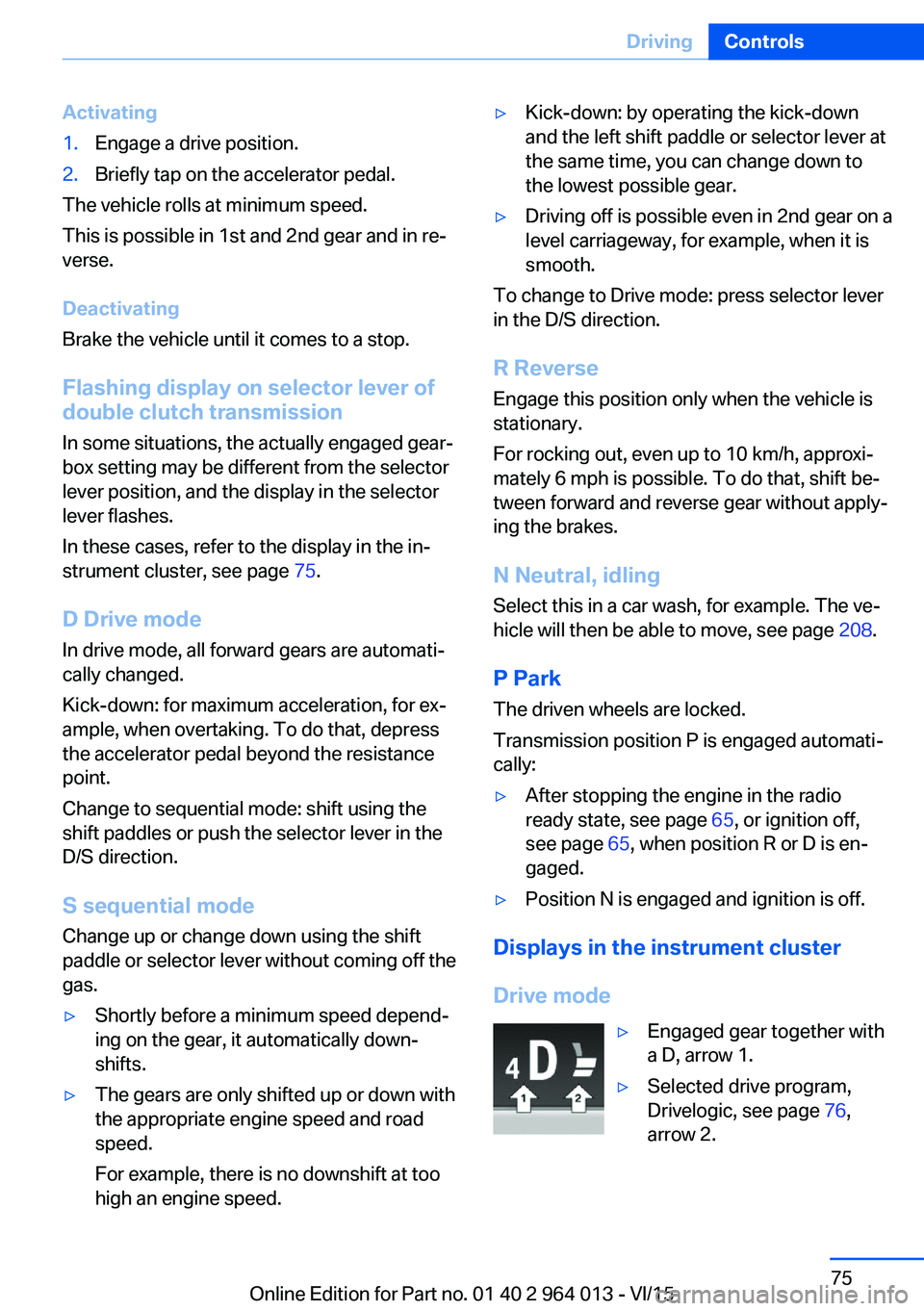
Displays in the instrument cluster
Drive mode
▷Engaged gear together with
a D, arrow 1.▷Selected drive program,
Drivelogic, see page 76,
arrow 2.Seite 75DrivingControls75
Online Edition for Part no. 01 40 2 964 013 - VI/15
Page 107 of 228
Tyre Pressure Monitor TPM
Principle The system monitors the tyre pressure in the
four fitted tyres. The system warns if the infla‐
tion pressure in one or more tyres has fallen
considerably. To do this, the sensors in the
tyre valves measure the tyre pressure and tyre
temperatures.
Note
To operate the system, also follow the other
information and notes under tyre inflation pres‐
sure, see page 175.
Operating requirements For the system, a reset must have been made
with the correct tyre inflation pressure, other‐
wise reliable signalling of a flat tyre cannot be assured.
Reset the system after adjusting the tyre pres‐
sure to a new value and after a tyre or wheel
change.
Always use wheels with TPM electronics to
guarantee the system functions without errors.
Status display
The current status of the Tyre Pressure Moni‐
tor TPM can be shown on the Control Display,
for example whether the TPM is active.
On the Control Display:1."Vehicle information"2."Vehicle status"3. "Tyre Pressure Monitor (RDC)"
The status is displayed.
Status control display The tyre and system status is denoted by the
wheel colour and some text on the Control Dis‐
play.
All wheels green
System is active and is warning about the tyre
inflation pressures stored during the last reset.
One wheel yellow
A flat tyre or major loss of tyre inflation pres‐
sure in the tyre shown.
All wheels yellow
A flat tyre or major loss of tyre inflation pres‐
sure in several tyres.
Wheels grey
The system cannot detect a flat tyre. The rea‐
sons for this are:▷System reset is performed.▷Malfunction.
Additional information
The current tyre inflation pressures and, de‐
pending on the model, tyre temperatures are
also displayed in the status control display.
The values shown are current values and may
change due to the effect of driving mode or
weather conditions.
Running reset Reset the system after adjusting the tyre pres‐
sure to a new value and after a tyre or wheel
change.
On the Control Display and on the vehicle:
1."Vehicle information"2."Vehicle status"3. "Perform reset"4.Start the engine – do not drive off.5.Resetting tyre pressure: "Perform reset".6.Drive off.
The wheels are shown grey and the status ap‐
pears on the display.
After driving for a short time over 30 km/h,
19 mph the set tyre inflation pressures are ac‐
Seite 107SecurityControls107
Online Edition for Part no. 01 40 2 964 013 - VI/15
Page 108 of 228
cepted as target values. The reset is run auto‐
matically while the vehicle is in motion.
After a successfully concluded reset, the
wheels are shown in green on the Control Dis‐
play and "Tyre Pressure Monitor (RDC)
active." is shown.
You can interrupt your drive at any time. Reset
resumes automatically when you continue
your journey.
Message if tyre inflation pressure is
low
The yellow warning lamp is illuminated.
A Check Control message is shown.▷There is a flat tyre or substantial
loss of tyre pressure.▷No reset has been done to the system.
Consequently, the system warns of the
tyre pressures of the last reset.1.Reduce your speed and carefully stop the
vehicle. Avoid violent or sudden braking
and steering manoeuvres.2.Determine which wheel is damaged. Do
this by checking the tyre inflation pres‐
sures with the aid of the Mobility System.
Correcting the tyre inflation pressure3.Remedy the flat tyre with the Mobility Sys‐
tem or replace the damaged wheel.
When there is a message that the tyre inflation
pressure is low, the Dynamic Stability Control
DSC may be switched on.
Message with required tyre inflation
pressure test
In such situations, a check control message is
displayed:
▷System has detected a wheel change, but
no reset has been run.▷Filling was not performed according to the
regulations.▷The tyre inflation pressure has dropped
compared to the last confirmation.If that is the case:▷Check the tyre pressure and adjust as nec‐
essary.▷Reset the system after a wheel change.
System limits
The system is not working correctly if no reset
has been run, for example, a flat tyre is repor‐
ted in spite of the correct tyre inflation pres‐
sure.
Tyre inflation pressure depends on the tem‐
perature of the tyre. By increasing tyre temper‐
ature, for example, when driving or with solar
radiation, the tyre inflation pressure increases.
Tyre inflation pressure decreases if the tyre
temperature drops. Through this behaviour, a
warning may be triggered if there are major
temperature drops, due to the given warning
limits.
No warning can be given by the system of ex‐
treme, sudden tyre failure caused by external
factors.
Malfunction The yellow warning lamp flashes and is
then illuminated continuously. A Check
Control message is shown. No flat
tyres or loss of tyre pressure can be detected.
This may indicate one of the following:
▷Wheel without TPM electronics is fitted:
have the vehicle checked by a Service
Partner or a qualified specialist workshop if
necessary.▷Malfunction: have the system checked by a
Service Partner or a qualified specialist
workshop.▷TPM has not completed a reset. Run a re‐
set of the system again.▷Fault due to systems or devices with the
same frequency: the system is automati‐
cally reactivated upon leaving the field of
interference.Seite 108ControlsSecurity108
Online Edition for Part no. 01 40 2 964 013 - VI/15